An integrated simulation system for operating solar sail spacecraft
ZHENG Yaru, LI Qinglong, XU Ming, and DONG Yunfeng
School of Astronautics, Beihang University, Beijing 100191, China
Abstract: An integrated simulation system for solar sail spacecraft with individually controllable elements (SSICE) is investigated in this paper, including the modelling of power management, thermal control, attitude control, umbra prediction, and orbit prediction subsystems.Considering the self-control and reactivity subsystems, an agent based method is applied to develop the subsystem models.Each subsystem is an individual agent component, which manages itself autonomously and reacts to the requirements from other agents.To reduce computing burden on a specified computer and improve the suitability and flexibility of the integrated simulation system, a distributed framework is employed in the system by deploying agent components on different computers.The data transmission among agents is based on the transmission control protocol/Internet protocol (TCP/IP).A practical example of sun pointing is used to test the operating effect of the integrated system and the working condition of subsystems.The simulation results verify that the integrated system has higher sun pointing accuracy, quicker dynamical response to variations of the lighting, attitude and temperature and fewer computing resources with effective and accurate subsystems.The integrated system proposed in this paper can be applied to solar sail design, operation, and mission planning.
Keywords: solar sail spacecraft, integrated system, agent, distributed simulation, individually controllable element.
1.Introduction
With the development of the material technology, control theory and electric propulsion, the solar sail spacecraft has become a viable choice for space exploration.In contrast to traditional spacecraft with chemical propulsion or ion propulsion, the solar sail can attain a sustained acceleration and achieve attitude control without any fuel consumption, which avails long-time work for the spacecraft.MacNeal [1] put forward the spinning solar sail with the shape of helicopter wing.Jet Propulsion Laboratory of NASA designed a solar sail with 127.5 m long sails, and identified the feasibility in the 1970s.Russian developed a reflector experiment and successfully unfolded“Znamya 2” reflector in 1994 [2].Japan Aerospace Exploration Agency (JAXA) fulfilled a spreading experiment of the glove-shaped solar sail and the fan-shaped solar sail in 2004 [3], which made the development of solar sail possible.NASA made a space expansion experiment by the space shuttle in 1996 [4], which verified robustness and reliability of inflated deployment structure.German Aerospace Center developed the expansion test of square solar sail [5].NASA sponsored a series of activities about solar-sail technology, systems design, and hardware development from 2004 to 2007 which verified many key technologies [6].JAXA firstly achieved expansion and operation of the solar sail on the orbit of“IKAROS” in May, 2010 [7], while NASA also accomplished the solar sail tasks on “NanoSail-D 2” in November, 2010 [8].
For the solar sail spacecraft on orbit, it is important to build power subsystem, thermal subsystem and attitude subsystem.Therefore, an integrated system which contains control and operate subsystems are very suitable for solar sail spacecraft.Simulations relying on an integrated system can be speeded up, meanwhile the system also plays an important role in mission planning and spacecraft control on orbit.The payload subsystem just acquires power and thermal assurance; therefore, the payload subsystem can be combined with them.As for the structure and mechanism subsystem, it has been fixed after launch, which is unnecessary to build the simulation model.Liu et al.[9] gave a solar cell array model with coupled multi-physics equations of photovoltaic energy conversion in virtual test bench (VTB) environment.The model explicitly showed the flow of electro-thermal transition and energy conservation of the solar array, but it paid less attention to the allocation and control of power.Bailey and Lovgren [10] analyzed the electric power system (EPS), which provided a non-linear model and was a good tool for designing, but the system had a high request for computing ability which did not fit the solar sail spacecraft.Alhama et al.[11] showed a network simulation method (NSM) for the numerical prediction of spatio-temporal temperatures in multi-layered composite walls.NSM is hardly based on SINDA/FLUINT on NEVADA and the choice of initial parameters.Thus, it is unqualified for the real-time and dynamical thermal control of spacecraft.Garmendia et al.[12] studied a small-size thermal mathematical model generated by genetic algorithms.However, the computer elapse time is too long to transplant directions to the solar sail directly.Li [13] adopted a double-layer aggregate model to build the real-time simulation platform of the thermal control system.Although the platform owned a high simulation precision, it depended on options of thermal parameters excessively, and many variables hardly making sense in the solar sail have been taken into the model.Therefore, a simplified model contributes much to thermal control simulation of the solar sail.
As for the attitude subsystem, the theory is very mature, and it has been a part of integrated simulation system of spacecraft already.The spacecraft control toolbox(SCT) from Princeton satellite systems [14] provided an integral attitude control strategy for common spacecraft,and applications in many commercial satellites proved its reliability.However, with the dynamical model of solar sail and the attitude control system different from normal satellites, SCT has less similarity with other tasks.Sun et al.[15] gave out a system of design, simulation, and evaluation for the small satellite, whereas, considering peculiarity of the solar sail spacecraft structure and control system, the simulation model was unfit for the solar sail.Sakamoto et al.[16] analyzed the deformation of solar-radiation pressure on spacecraft based on the nonlinear finite element method, which lacks enough research on attitude and orbit state.Gorbunova et al.[17] described the impact of spacecraft center mass movements on dynamical model, which mattered to attitude modelling of solar sail spacecraft, but it still did not provide an integrated attitude and orbit control model.All in all, mainstream research about solar sail has not studied spacecraft from an overall perspective and integrated all subsystems yet.
Considering the future swarm mission and modular assembly spacecraft, there exists a high demand for the flexibility of the integrated system and autonomy of each component.Furthermore, with increasing systematic complexity and individual autonomy, more computing resources to achieve component management and data processing are in urgent need.Therefore, a new simulation system is built in this paper firstly, which integrates power management, thermal control, attitude adjustment,umbra prediction, and orbit prediction subsystem together, and fulfills full-scale and holistic simulation of solar sail spacecraft.Then, this paper also applies the agentbased modelling method to the simulation system, which makes each subsystem be an individual agent component with autonomy, interaction, and society.Such agent components constitute the integrated system, and accomplish power management, thermal control, and attitude adjustment for solar sail spacecraft [18].In addition, the system deploys each agent in different computers and utilizes the transmission control protocol/Internet protocol(TCP/IP) to interact with each other, which can effectively allocate computing resources to reduce the burden on a specified computer.Besides, an attitude control strategy of solar sail spacecraft with individually controllable elements (SSICE) [19] is integrated into the simulation system, which is used to verify the property of the integrated system.Then, simulations based on sun-pointing mission have been carried out, which provide attitude and orbit control effects.
2.System frame and subsystem components
2.1 Frame and working flow of the integrated system
In agent-based modelling, a system is modeled as a collection of autonomous decision-making entities called agents.A distributed simulation framework is built based on the agent modelling method.Each agent individually assesses its situation by interaction with other agents or perceives the environment and acts on the basis of a set of rules [20].To reduce computing burden on a specified computer and improve the adaptation and flexibility of the integrated simulation system, a distributed framework is employed in the system by deploying agent components on different computers respectively, and the data transmission among agents is based on the TCP/IP.It is quite different from the traditional satellites, the SSICE has a very tense coupled attitude-orbit control subsystem because the sail’s orbit is controlled by its attitude indirectly.
A typical structure of the solar sail agent is shown in Fig.1, where the agent obtains environment information and requirements from other agents, and reacts according to pre-set rules, such as sun pointing, temperature maintaining, or power balance, as well as transmits order or request to other agents by IP addresses.Thus, every agent is an independent, autonomous, social, and reactive entity, which is appropriate for such a complex system of solar sail spacecraft.

Fig.1 Typical structure of a solar sail agent
For a solar sail spacecraft, it is divided into five agent subsystems or components, including power management, thermal control, attitude control, orbit prediction,and umbra prediction subsystems.The power management subsystem supplies power to all the on-board equipment, the thermal control subsystem provides suitable environment, and the attitude adjustment subsystem furnishes payload with proper attitude condition, such as a stable imaging condition.The three subsystems vary with time, lighting condition, and environmental variation.Thus, umbra prediction subsystem is essential to adjust the states of other subsystems.In addition, SSICE is quite dependent on solar position and direction, which requires a very accurate solution to umbra prediction.Thus, the umbra prediction model needs to be a subsystem that is as important as attitude control, stability control, and energy subsystem.Considering that each subsystem is independent in function and can react autonomously to variations of the space environment and requirements from other subsystems, all the subsystem are inserted with an agent component [21].In addition, all the variables used in this paper are defined in Table 1.
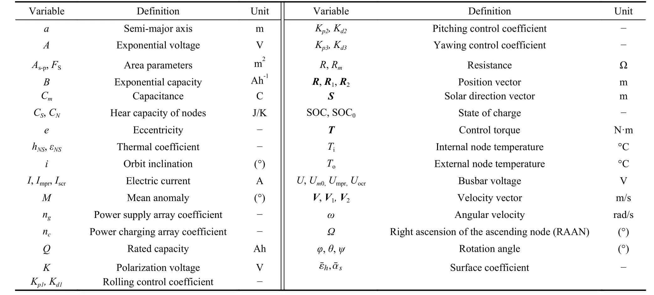
Table 1 Nomenclature
Concretely, as shown in Fig.2, the relationship of different agent components is listed as follows.Firstly, the orbit prediction component will output the position vector of the solar sailRto umbra model component, and output the position vectorR, velocity vectorV, and orbit angular velocityωof the solar sail to attitude control component.Secondly, the umbra prediction component will output the umbra symbol “Flag” to the thermal control component and power management component.Thirdly, thermal control component will export the external node temperatureToto the power management component.Fourthly, after the attitude control component changes the shape and area ratio of the sail, it will output the solar radiation perturbation to the orbit prediction component.
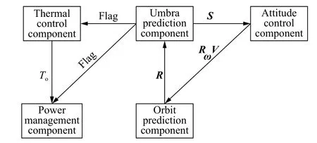
Fig.2 Structure and logistic diagram of the solar sail
Considering that the simulation system is based on agent modelling, the structure accords with the distributed simulation method.This paper takes a framework as shown in Fig.3 to accomplish distributed simulation.Five agent components are respectively configured in five computers, and the orbit prediction agent computer is the main computer, which receives and distributes data from or to other agent computers, and also output control orders to motors of solar sail, power management, and thermal control components.Data transmission among different agents relies on the TCP/IP, and recognition of each agent depends on the IP address.It should be noted that the configuration of system is flexible.Five computers are not a must, and fewer computers would also be feasible, as long as the IP address of each agent is configured correctly.Finally, this paper realizes such a distributed simulation system based on Matlab tool.
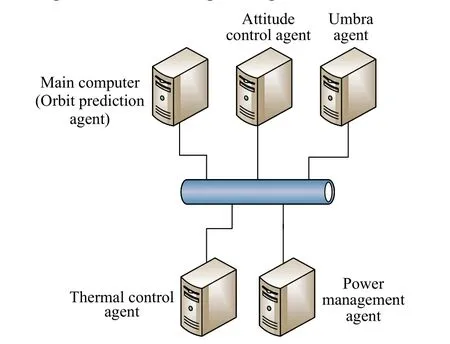
Fig.3 Structure of distributed simulation
2.2 Subsystems modelling and working flow
According to the statement in Section 2.1, modelling and working flow of the five-subsystem will be described separately in this section.
As for the structure of the solar sail, there are three configurations, including the heliogyro, disk sail, and square sail [22].Because the unique SSICE structure can fulfill attitude adjustment of solar sail, this paper takes the SSICE for investigation.The SSICE structure is shown in Fig.4(a), where Element 1 are motors (brown squares), Element 2 is the solar sail (orange rectangles),Element 3 is the SSICE frame keeping its shape (blue lines), and Element 4 is the payload (brown squre in the middle).The working flow of SSICE is that motors drive solar sail rotation or twist, and the solar radiation pressure drives SSICE pitching, yawing and rolling.Fig.4(b)shows the relationship between the control torqueTand the rotation angleθof motors.Luo et al.[19] put forward the attitude dynamics of SSICE, the relationship between controlling torque and the differences of two motors’ angles at both ends of each blade is shown as
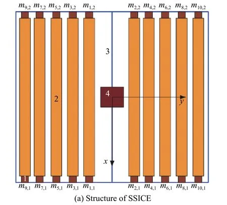
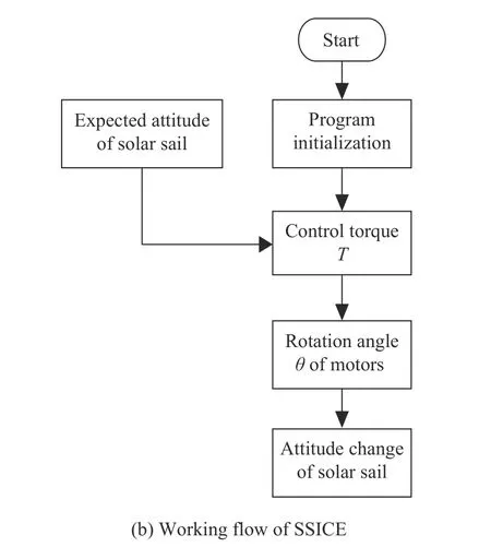
Fig.4 Model of SSICE
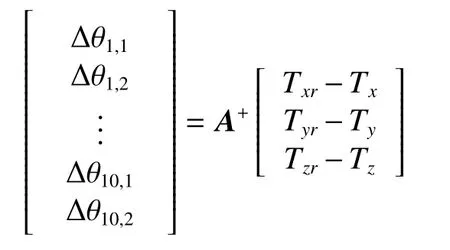
whereAis the status transfer matrix, andA+indicates generalized inverse of matrixA, whose expression is shown as
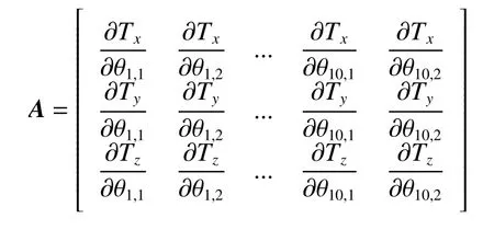
whereTxr,Tyr,TzrandTx,Ty,Tzare control torques meeting attitude adjustment and solar pressure torques to three axes respectively.Δθi,1or Δθi,2is the rotation angle of each motor, and the subscripts 1 and 2 indicates two sides of each panel of the solar sail.The expression of elements in matrixAis
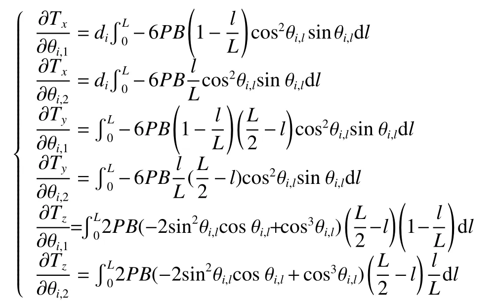
wherePis the solar pressure, andBandLare the breath and length of each panel respectively.
Thus, the motor rotation angles satisfying the attitude adjustment requirement can be obtained.Attitude adjustment can be realized by controlling motor rotating at proper angles with the help of the PD controller.The variablemab(ab=1,2,3,···) is the mass of the numbered motor on the solar sail.
The orbit prediction component is the basis of all the simulation systems, which predicts orbit position and velocity at a specific time.In this paper, the agent component of orbit prediction is designed according to the highprecision orbit propagator (HPOP) model [23].The HPOP model considers the main perturbative forces acting on the satellite, including high order gravitational field, earth tide, lunisolar attraction, atmospheric drag,and solar radiation pressure.The orbit prediction component can derive the solar sail’s position vectorR2and velocity vectorV2at momentt2from position vectorR1and velocity vectorV1at momentt1, realize the transformation betweenR,V, and orbital elements, and then calculate the angular velocityωthrough the orbit elements.The detailed structure and flow are shown in Fig.5(a) and Fig.5(b) respectively.The HPOP model takes high order earth gravitational field, earth tide, atmosphere drag, the sun’s and the moon’s gravitation, and the solar radiation pressure into perturbation model [23].The high order gravitational field model takes seven orders perturbative term into consideration.The atmosphere drag is based on USSA76, i.e., US Standard Atmosphere 1976.Finally, Cowell method is used to solve the differential equation of motions and then to attain position and velocity of spacecraft at any time.
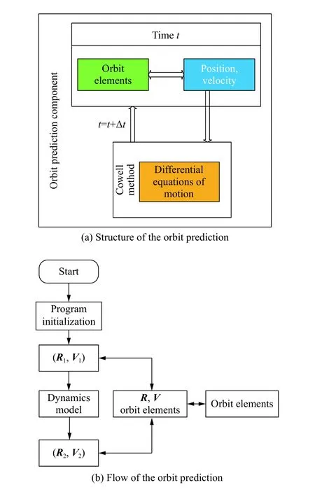
Fig.5 Orbit prediction component
The umbra prediction component is the foundation of power management and thermal control, which provides the “umbra flag” in a time interval.The component can calculate the solar position vectorSin the geometric inertial coordinate system, and obtain the position vectorRof the solar sail.Based on the prediction algorithm in [24],the relationship of the sun, earth, and the spacecraft are shown in Fig.6(a).An umbra symbol “Flag” of the onorbit solar sail can be obtained as shown in Fig.6(b).The umbra symbol is submitted to the power and thermal control system.When the spacecraft is in the umbra, the power system supplies power to the payload and the thermal control system; if not, the solar sail charge batteries and power for the payload.Umbra is the main factor that influences the function of the spacecraft and the lifetime of on-board facilities.Exactly predicting the time when the satellite enters and leaves the umbra can contribute much to the management of the power system, the control of the satellite’s temperature, and imaging mission planning.This section regards the sunlight as parallel light, and adopts the cylindrical shadow model.
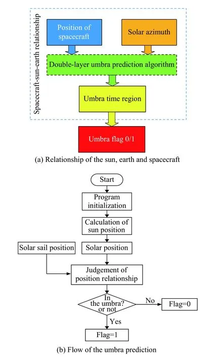
Fig.6 Umbra prediction component
Jia [24] put forward a double-layer structure algorithm used for umbra prediction on board.The algorithm defined the time node of in or off umbra region as “nd”.In each of the node, a step changing numerical algorithm is used to predict the next time node.Thus, the analytical algorithm is used to solve the difference between the accurate time node and the iterative solution.The step changing algorithm is used to check the solar-sail spacecraft locating in or off umbra in specific time which makes a mass of computation no sense in other time.
The thermal control component is used to keep a comfortable environment for the solar sail frame and the payload, which is based on the bilevel lumped parameter model in [25].The model is shown in Fig.7(a).The detailed flow of thermal control is shown in Fig.7(b).First,the umbra symbol “Flag” confirms the space heat flux acting on the solar sail.If “Flag” is equal to 0, the space heat flux is solar radiation heat flux, reflecting heat flux and terrestrial infrared radiation heat flux (denoted as space heat flux state I).If “Flag” is equal to 1, the space heat flux is solar radiation heat flux (denoted as space heat flux state II).
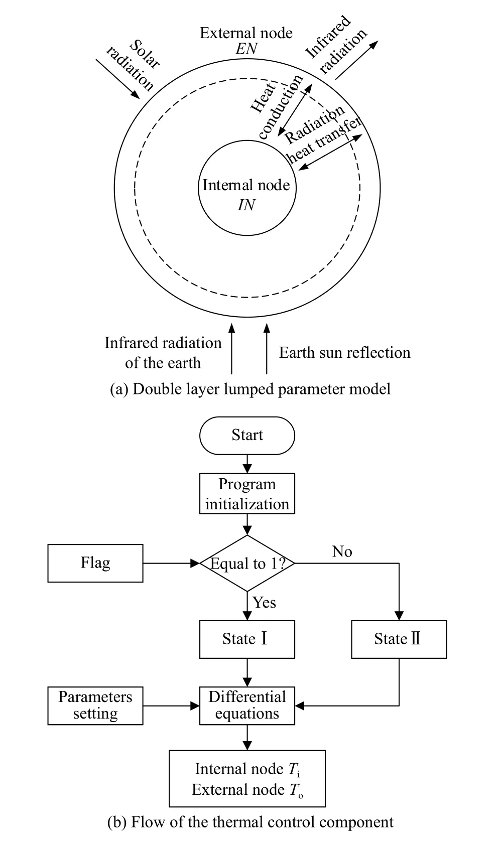
Fig.7 Thermal control component
By solving differential equations, the real-time temperature of the internal and external nodes of the solar sail on orbit can be obtained.Inside facilities of the solar-sail spacecraft can be treated as isothermal and be simplified as the internal nodeIN.Similarly, external facilities also are regarded as isothermal and simplified as external nodeEN.The internal and external nodes [26] can be summarized as

whereCNandCSare the lumped heat capacity of the internal node and external node,TNandTSare the node temperature of the internal and external nodes,hNSis the thermal conductivity coefficient between two nodes,εNSis the radiant heat-transfer coefficient between two nodes,FSis the superficial area of the external node,QNis the power consumption of the internal node, andQ1,Q2, andQ3are space heat fluxes, respectively representing the solar radiation, the earth infrared radiation, and the sunlight reflected from the earth.
The power management system is applied to power or charge for the solar sail [27] and the payload, which is the precondition of all the subsystems on board working normally.When the solar sail is at the lighting region (“Flag”is equal to 0), the power supply array will power the bus bar, and the charging array will charge the accumulators(denoted as working mode I).If “Flag” is equal to 1, the power supply array and charging array stop working, and the accumulators will power the bus bar (denoted as working mode II).Then, the voltage of the bus barUand the value of state of charge (SOC) can be obtained by calculating differential equations.Besides, the output characteristics of the solar cell array is influenced by the temperature.Hence, the external temperature nodeTowill be used to confirm the characteristics.The structure and working flow of power system is shown in Fig.8.This section chooses silicon solar cell as simulation case to research its mathematical model [27].
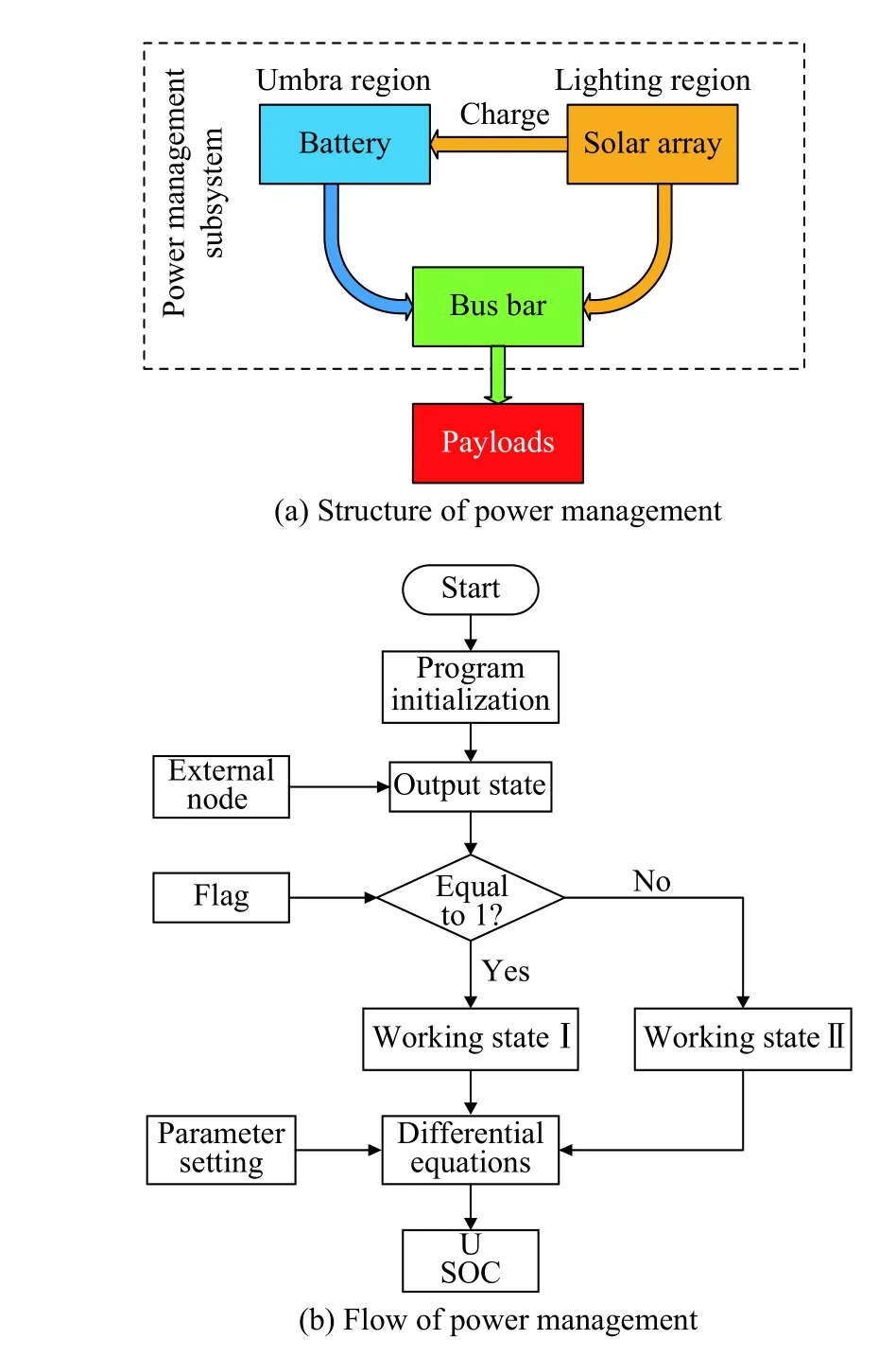
Fig.8 Power management component
When the spacecraft is operating in the lighting region,the power supply array will charge the bus bar, and use parallel regulator to ensure that the bus bar voltage is in the permissible range.According to every component’s mathematical model, the state equations of the power supply array are shown as
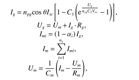
whereIgandUgare the terminal current and voltage of the power supply array, e is the natural constant whose value is 2.708 28,npgandnsgare cascade and parallel cells numbers of the power supply array,Rgis the internal resistance, αiis the split ratio of theith circuit,Imis the partial current,Vocis the open voltage,ngis the circuit number of the power supply array, andIg,UgandImof the power supply array can be obtained.
When the spacecraft is operating in the lighting region,and the power supply array can satisfy the spacecraft system’s power requirement.Charging array will charge the accumulator.The state equations of the charging array are shown as
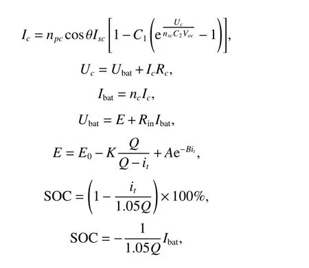
whereIcandUcare terminal current and voltage of the charging array,npcandnscare cascade and parallel cells numbers of the charging array,Rcis the internal resistance, andncis the circuit number of the charging array.Rinis the internal resistance of the battery,UbatandIbatare the terminal voltage and the current of the battery respectively.
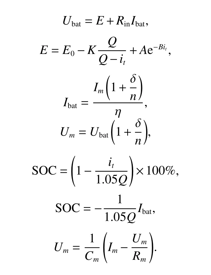
When the spacecraft is operating in the shadow region,the solar cell array cannot charge the bus bar.Or even though the spacecraft is still in the lighting region, the power supply array cannot satisfy the bus bar’s power requirement.The accumulator will discharge to meet the requirement.The state equations is of discharging are written as
The attitude control component is mainly used for sun pointing, and the attitude control strategy is displayed in Fig.9(a).The control system will calculate the deviation and motor rotation angles according to the solar positionSand the current positionR, velocityV,and the angular velocityω.The relationship between control torque and motor rotation angle can be found in [28].The SSICE employs several electronic motors to control its attitude,not the traditional momentum wheels and other actuators.Therefore, a special power management model is adopted with the level of model development (LMD) up to current and voltage of SOC and bus.The operation law of motors satisfies the requirement of attitude adjustment, changes the shape of the sail, the solar radiation pressure, and also changes the dynamical model of the solar sail.Meanwhile, the variation of the dynamical model influences the velocity vectorVand position vectorR, which influences the orbit prediction model.The detailed working flow and the mathematical model are shown in Fig.9(b).
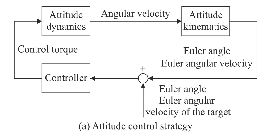
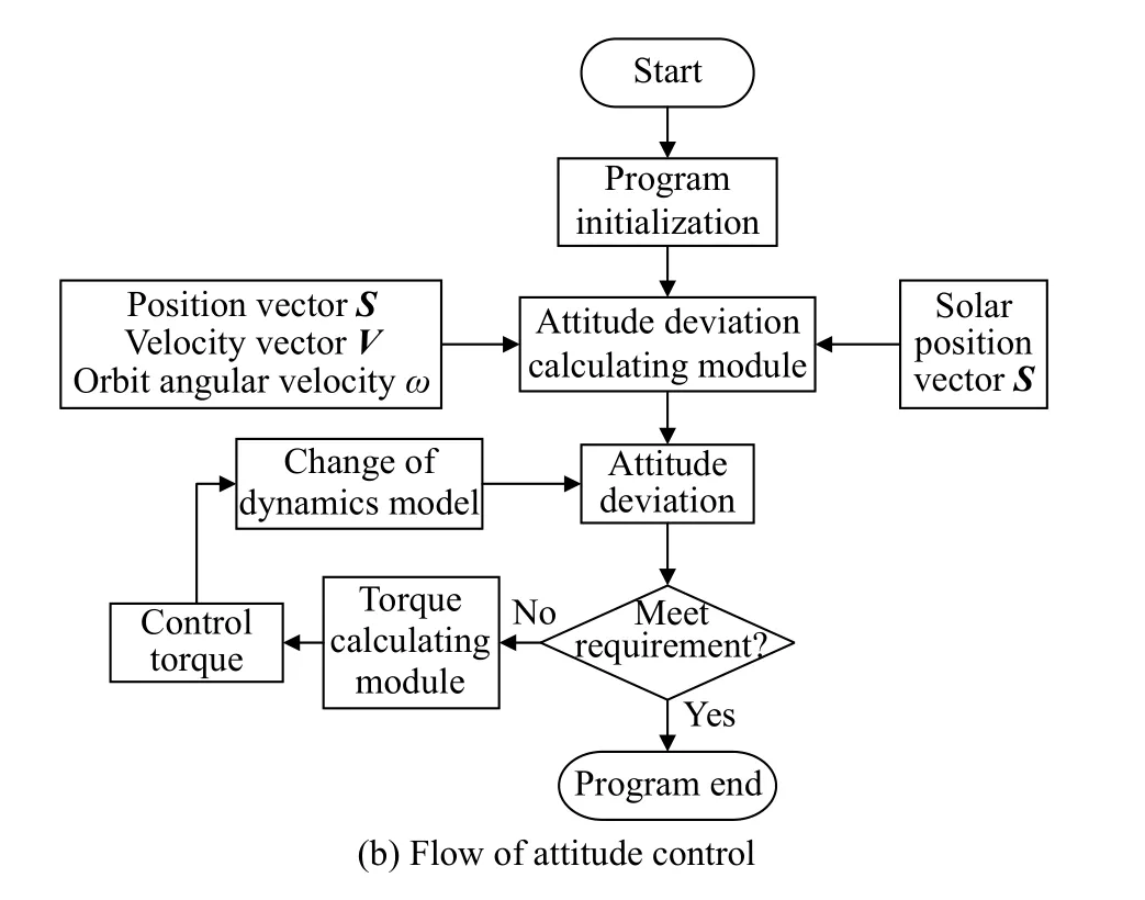
Fig.9 Attitude control component
3.Application of the integrated system into solar sail spacecraft
To verify the reliability of the integrated system, a test for the whole system is necessary.This section illustrates the real-time distributed simulation of the on-orbit solar sail system based on a specified case, where Section 3.1 shows the demand of the mission and Section 3.2 shows the simulation result and analysis about the mission.
3.1 Description of the mission requirements
Considering the function of the integrated simulation system, this section tests the property of the simulation system by a solar sail spacecraft mission, including sun pointing of the solar sail frame, temperature keeping and power allocation.During the whole simulation, the solar sail frame should keep pointing to the sun, which means that thez-axis of the SSICE frame only has a sufficiently small angle difference with the sunlight.The angle is limited to be less than six degrees.In order to satisfy power demand of the payload, the power management subsystem should provide at least 3.3 V and 12 V voltage.Besides, to ensure the normal operation environment of the payload, the thermal control system must guarantee that the internal environment temperature is in 0?45°C.
3.2 Simulations by the integrated system
The initial moment of the simulation is set as 12:00:00AM, January 1st, 2022 (UTC).The orbital elements at the initial moment are depicted in Table 2.Parameters of the power system and the thermal control system are shown in Table 3 and Table 4.The simulation parameters of the attitude control system are described in Table 5.Due to the unique attitude control, the data interaction among subsystems is greater than other simulation systems built for traditional satellites.
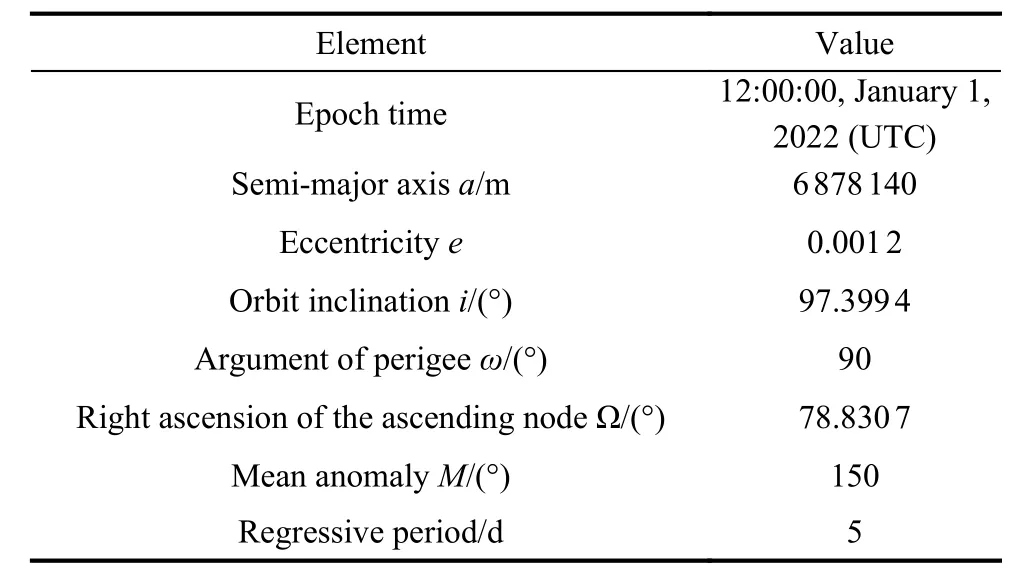
Table 2 Initial orbit elements
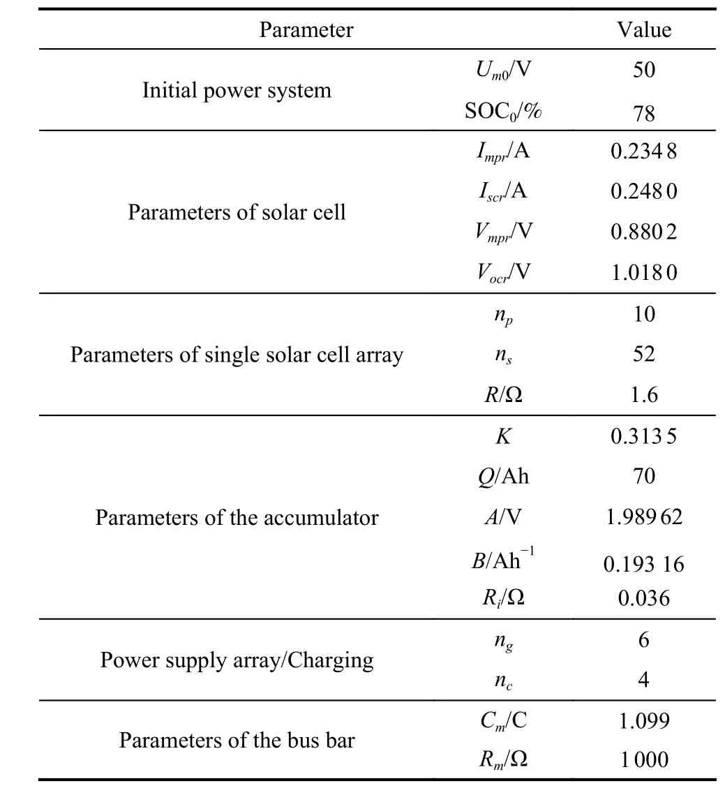
Table 3 Parameters of the power system
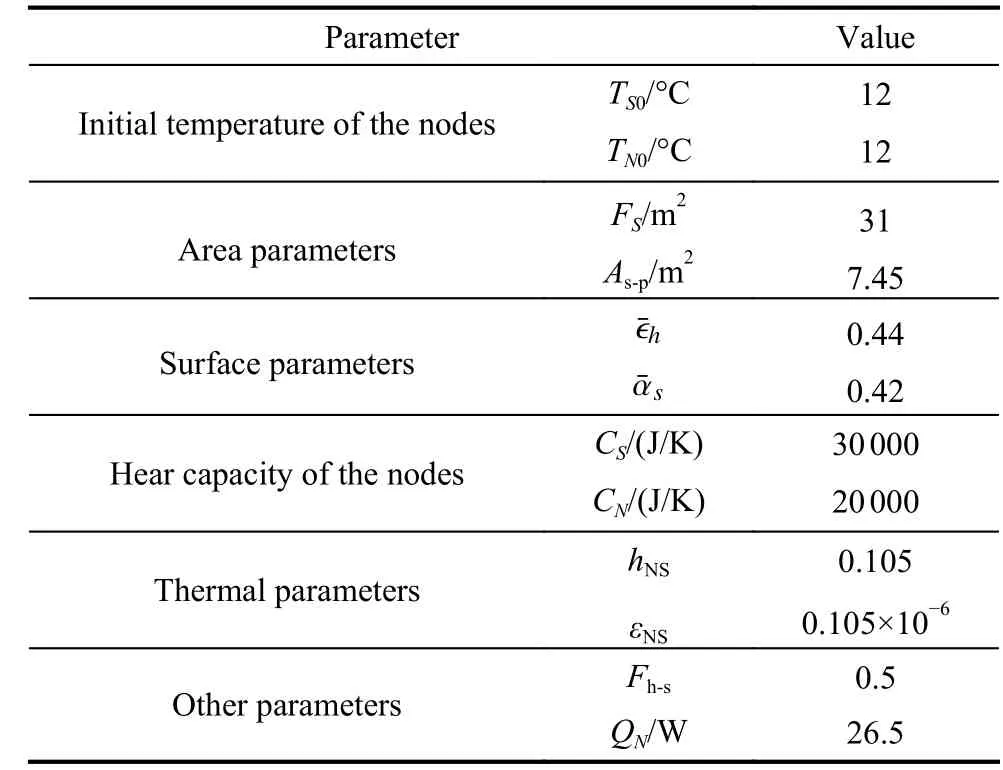
Table 4 Parameters of the thermal control system
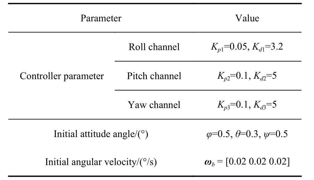
Table 5 Simulation parameters of the attitude control system
The numerical results of these simulations are displayed as follows.The time history of the solar azimuth is shown in Fig.10.It is indicated that the spacecraft can be controlled within 5° in a short time (no more than 100 s),and the bias of the solar azimuth is less than 1°, which satisfies the accuracy requirement of sun pointing and engineering requirement.The time history of the Euler angle and the Euler angular velocity are shown in Fig.11 and Fig.12.The controlled Euler angle velocity is near the value of 0 in most time of the simulation, which means attitude control system only works when necessary.The attitude adjustment time is less than 2 000 s in an orbital period, which has little impact on the orbit elements.Their variation period is the same as the regressive orbital period, indicating that the attitude adjustment strongly accords with the orbit variation.Time history of control torque is described in Fig.13.The controlled motors ensures that the SSICE frame fulfills the sun pointing and satisfies the bias accuracy request.The four figures mentioned above prove that the attitude control system work effectively and reliably.
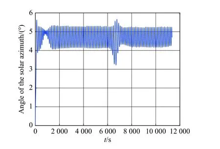
Fig.10 Time history of solar azimuth
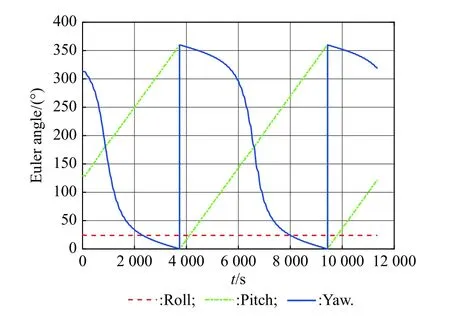
Fig.11 Time history of Euler angle

Fig.12 Time history of Euler angular velocity
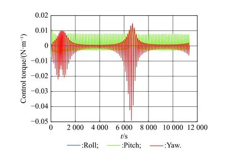
Fig.13 Time history of control torque
The time history of bus bar voltage and SOC of the accumulators are illustrated in Fig.14 and Fig.15.It is obtained that the variation of bus bar voltage is less than 4 V,which satisfies the power demand.In addition, SOC of accumulators varies from 75% to 95%, which belongs to the normal working range.Therefore, the power system can satisfy power requirement of on-board facilities.
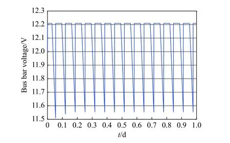
Fig.14 Time history of bus bar voltage
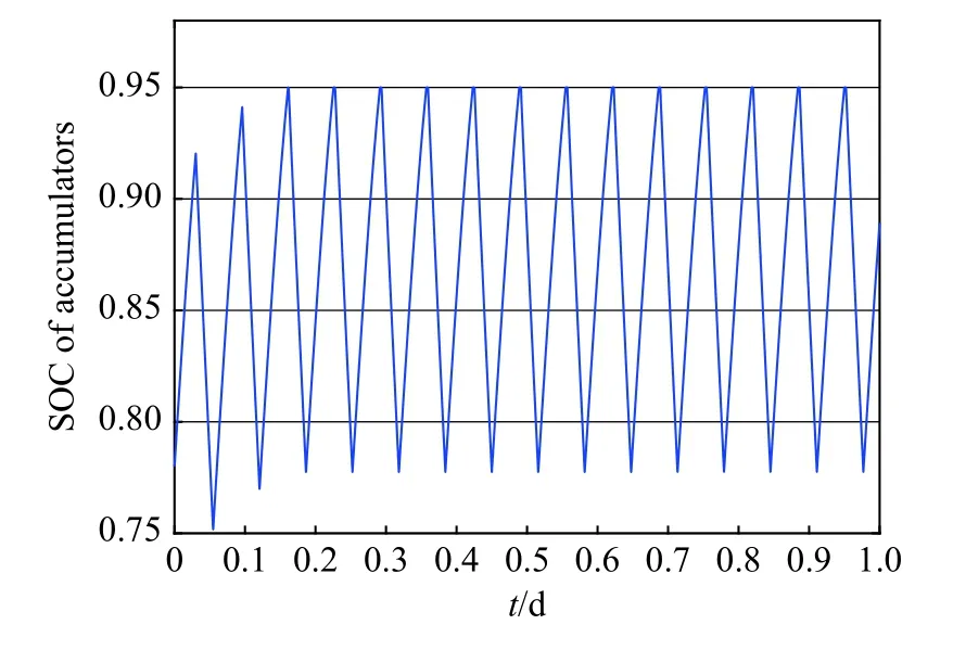
Fig.15 SOC of the accumulators
As displayed in Fig.16, during the simulation time, the external node temperature varies from ?3oC to 21oC, and the internal node temperature varies from 3oC to 18oC.The two variations satisfy ordinary working requirements of the payload and SSICE.
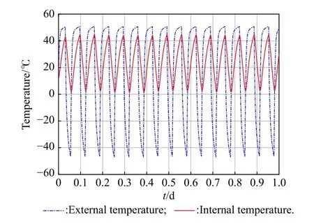
Fig.16 Time history of node temperature
Otherwise, during the five-day simulation of regressive orbit, the computing time of the simulation system is less than 30 s, which means the algorithm of the integrated system is quick and highly effective.In addition, the distributed simulation system performs well, and the integrated system can achieve the attitude control effectively.The simulation successfully confirms the ability for full-scale simulation, attitude control, and operation for the solar sail spacecraft.
4.Conclusions
This paper presents an integrated architecture of the SSICE and proposes a distributed framework simulation which adopts the agent modelling method.From the modelling of viewpoint, quite different from the traditional satellites, the SSICE has a strongly-coupled-attitude-orbit control subsystem because the sail’s orbit is controlled by its attitude indirectly.In addition, SSICE is quite dependent on solar position and direction, which requires a very accurate solution on umbra prediction.However, the traditional umbra prediction is just a simple and open-loop subroutine, which is not suitable for the current architecture designed for SSICE.
Four key solutions are used to solve the technical problems above.Firstly, a new type of SSICE which employs several electronic motors to control its attitude, not the traditional momentum wheels and other actuators, is proposed.Then, a special power management model is adopted with the LMD up to the current and the voltage of SOC and bus, which is considered as one of the contributions in this paper.Thirdly, all the subsystems are designed into a highly autonomous agent component, independently working as an individual and cooperating with other agents for the whole mission.Finally, five agents with different LMD are respectively configured in more than one computer with the orbit prediction agent located in the main computer, and the data are received and distributed from or to other agent computers by the TCP/IP.
The integrated system is proved to be advanced and feasible in this paper, there also exist some other future improvements.It can be applied to functionalizing the integrated system by secondary development interfaced with satellite tool kit, automatic dynamic analysis of mechanical systems and other professional software as well as introduce an iteration cycle/architecture between the integrated system and design algorithms of subsystems to produce a useful design proposal for a possible solar-sail spacecraft mission.
 Journal of Systems Engineering and Electronics2021年5期
- Journal of Systems Engineering and Electronics的其它文章
- Belief reliability modeling and analysis for planetary reducer considering multi-source uncertainties and wear
- M-FCN based sea-surface weak target detection
- New Developments on Fault Detection and Diagnosis (FDD) and Fault-Tolerant Control (FTC) Techniques
- A method to realize NAVSOP by utilizing GNSS authorized signals
- Reliability analysis of k-out-of-n system with load-sharing and failure propagation effect
- An iterated local coordinate-exchange algorithm for constructing experimental designs for multi-dimensional constrained spaces
