Experimental results of a magnetic field modification to the radio frequency driver of a negative ion source
Junwei XIE (謝俊煒),Yahong XIE (謝亞紅),*,Jianglong WEI (韋江龍),Lizhen LIANG (梁立振),Xufeng PENG (彭旭峰),Yuwen YANG (楊宇雯),Yuming GU (顧玉明),Chundong HU (胡純棟) and Yuanlai XIE (謝遠來)
1 Institute of Plasma Physics,Hefei Institutes of Physical Science,Chinese Academy of Sciences,Hefei 230031,People’s Republic of China
2 University of Science and Technology of China,Hefei 230026,People’s Republic of China
Abstract A magnetic field produced by a current flowing through the plasma grid (PG) is one of the solutions to reduce the collisional loss of negative ions in a negative ion source,which reduces the electron temperature in front of the PG.However,the magnetic field diffused into the driver has some influence on the plasma outflowing.In order to investigate the effect of changing this magnetic field on the outflowing of plasma from the driver,a circular ring (absorber) of high permeability iron has been introduced at the driver exit,which can reduce the magnetic field around it and improve plasma outflowing.With the application of the absorber,the electron density is increased by about 35%,and the extraction current measured from the extraction grid is increased from 1.02 A to 1.29 A.The results of the extraction experiment with cesium injection show that both the extraction grid (EG) current and H- current are increased when the absorber is introduced.
Keywords: neutral beam injection,negative ion source,magnetic filter,radio frequency ion source
1.Introduction
The Comprehensive Research Facility for Fusion Technology (CRAFT) for the fusion project is developed in order to research and develop the fusion reactor and core components.A neutral beam injection (NBI) system is designed for the project as an auxiliary heating device.Considering that the neutralization efficiency of negative ions is higher than that of positive ions,a radio frequency (RF)-driven negative ion source based NBI (NNBI) system with a beam energy of 200–400 keV and neutral beam power of 2 MW is required[1].
The study concerning the negative ions and electron current density is essential and difficult in the project of CRAFT NNBI.In order to improve the application value in fusion engineering,the destruction rate of negative ions caused by collisions with energetic electrons and the coextracted electron current from the ion source should be reduced.It was found that the electron temperature is decreased from 5 eV to 1 eV with a magnetic filter field(MFF) in the expansion chamber [2].So,the MFF applied in negative ion sources with a large extraction area and generated by an electric current flowing through the PG is an effective method,and it has been applied in several negative ion sources [3–7].
The plasma driver that is an important part of the ion source should also be discussed.To optimize the MFF in the RF driver region,the minimum absolute value of the MFF|B| and negligibleBzcomponent is required in the driver region [8].This is because the maximum extraction current density was achieved when the minimum magnetic field strength appeared at the driver region [9] and the electrons were easily lost on the driver walls caused by the strongBzcomponent [10].Usually,the field in the driver region can be optimized by PG return wires placed between the driver and the ion source [11].However,it would introduce difficulties in the structural design caused by more and more complex MFF electric systems.Hence a simple,wireless and quick detachable method for the control of the MFF in the driver region is studied.
In order to study the effects of the new method in the process of plasma discharge,a control experiment was carried out in an RF-driven negative ion source at the Institute of Plasma Physics,Chinese Academy of Sciences(ASIPP).A Langmuir probe was used to detect the electron density according to the electron saturation current at a distance of 8 mm from the PG (figure 1).
2.Simulation results of a magnetic field modification
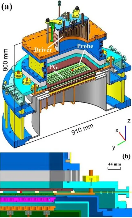
Figure 1.(a) Overall schematic representation and (b) cross-section of the Langmuir probe measurement point in the negative ion source (red dot on the yellow line).
The lower magnetic flux density in the driver can reduce the charge particles’ deflection losses and high-power loadings on the walls of the ion source and increase the plasma flowing from the driver.According to Maxwell’s equations,high permeability media applied in the environment with a magnetic field can ‘a(chǎn)bsorb’ the magnetic flux density to decrease its surroundings.The material of this media should be characterized by high permeability and high resistivity because eddy current losses and Ampere damping can be decreased.Meanwhile,delivery,market availability and price should be taken into account as the typical material parameters [12].The condition of the electromagnetic field can be satisfied with soft iron and silicon iron.In the simulation performed for figure 2,soft iron is used for the high permeability material.The simulation model based on the finite method has been widely applied in other research concerning the electromagnetic field [13–15].
2.1.Description of model
The model design based on the RF negative ion source at ASIPP is shown in figure 2.The size of the PG is 512 mm(length) × 396 mm (width) × 9 mm (height),192 extraction holes with a diameter of 14 mm in the extraction area.The magnetic field absorber is mounted at the RF driver exit (Z=200 mm).The model is simulated when the PG current flows along theY-axis at 2 kA as the typical value of the experimental research.
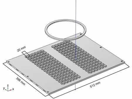
Figure 2.PG and magnetic field absorber structure.
2.2.Distribution of magnetic field
The magnetic field distribution in the beam source was simulated and the comparison of the horizontal component of magnetic flux densityBxalong the blue line (as shown in figure 2) perpendicular to the PG with or without a magnetic field absorber is shown in figure 3.The fieldBxat the driver exit is decreased from 0.1573 mT to 0.0717 mT—about a 54.4% drop.
The results indicate that the fieldBxat the driver region can be decreased when the magnetic field absorber is introduced (maximum Δ|B|=0.0986 mT),and the vertical component of the fieldBzat the driver region shows no great change compared to the structure without the absorber(maximum Δ|B|=0.0282 mT).
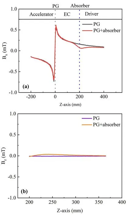
Figure 3.Calculated values for (a) the horizontal component of the field Bx in the beam source and (b) vertical component of the field Bzin the driver.
3.Plasma evaluation in the RF driver
The introduction of an absorber can make some differences to the magnetic field distribution,that the field around it can be ‘a(chǎn)bsorbed’ into the absorber,which affects the plasma in the driver (white frame in figure 4).The application of an absorber influences the magnetic field from the last turn of the antenna.The electron temperature near the absorber decreased from 3.8 eV to 3.3 eV—the change is less than 1 eV with an RF power of 50 kW.The decreasing electron temperature may be caused by a weakened RF magnetic field because part of the RF power is deposited on the absorber ring in the form of a magnetic field.
The predicted electron density distributions along theXaxis at the driver exit and expansion chamber are shown in figure 5.The decrease of the magnetic field at this region with the absorber results in the increase of electron density in the simulation.The electron density is increased from 1.5×10¹⁷m-3to almost 1.9×10¹⁷m-3at the driver exit and from 2.0×10¹⁷m-3to almost 2.2×10¹⁷m-3in the expansion chamber.
The simulation results of the plasma in the driver and expansion chamber indicate that the additional structure of the absorber hardly affects the normal discharge process,and it can be mounted on the expansion chamber backplate to weaken the MFF at the driver exit;the phenomenon indicates that there is more plasma flowing out of the driver.
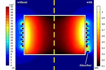
Figure 4.Distribution of electron temperature (inside the driver)and magnetic flux density (outside the driver) without/with the absorber.
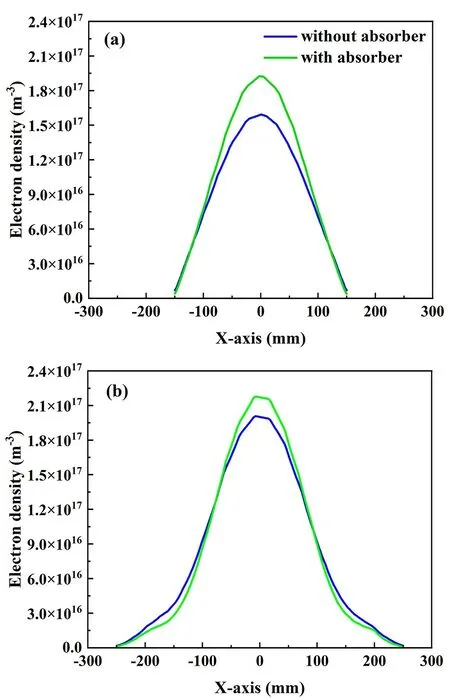
Figure 5.Calculated distribution of electron density (a) at the driver exit and (b) in the expansion chamber without/with absorber.
4.Experimental set-up and results
4.1.Magnetic field measurement
It is not easy to measure the magnetic field inside the ion source,so an experimental testbed was set up to verify the change of magnetic field with the absorber (figure 6).For the purposes of experimental verification and simplification,the magnetic field in the testbed was generated by permanent magnets (Bsurface=500 mT) instead of a current,and the magnetic poles are in thex-direction.The magnet is set at the zero point of the coordinate axis,and the iron absorber was placed 100 mm from the magnet.The magnetic flux density was measured along the axis by a Gauss meter with or without an absorber.The magnetic field direction is parallel to the table that is convenient for the probe to collect signals.Further,the slide was made of carbon fiber and aluminum to reduce the effects on the magnetic field.
The distribution of the magnetic flux density on the testbed (figure 6) is shown in figure 7.The fieldBxat the position of the absorber is decreased from 0.9 mT to 0.3 mT with the absorber;moreover,the field away from the absorber has a negligible change indicating that the magnetic field can be adjusted by the absorber locally.
4.2.Results of plasma experiments without and with an absorber on an ion source
In order to test the influence of an absorber on the plasma parameters,a soft iron absorber was mounted at the driver exit of the ion source,which is shown in figure 8.The hydrogen plasma was generated with a source filling pressure of 0.7 Pa and an RF power of 15 kW.The back plate of the driver is separated for ease of parts replacement.The magnetic field was generated by the electric current flow through the PG with currents of 1430 A,1610 A,1890 A,2060 A and 2330 A,respectively.
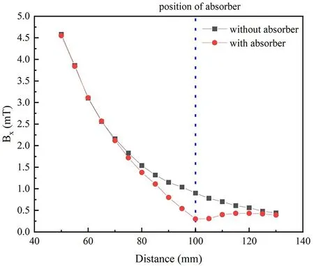
Figure 7.Results of the test with a permanent magnet.Shown is the magnetic flux density as a function of distance from the permanent magnet with and without an absorber ring.
The influences of the absorber on the plasma parameters without cesium injection are shown in figure 9.The electron density is decreased with the increased PG current both with and without an absorber.However,when the soft iron absorber is installed at the driver exit,the electron density is increased in different PG currents overall.The electron density is around 4.5×10¹⁶m-3and 6.1×10¹⁶m-3without and with the absorber—about 35% higher when the absorber is installed.The electron temperature is around 0.4 eV and 0.55 eV with the different PG currents,and the application of the absorber has little effect on electron temperature.Plasma potential is increased with the increasing PG current,and the potential with the absorber is slightly less than that without the absorber.
In order to further study the influences of the absorber on the ion source,extraction experiments have been carried out.Several co-extracted electron suppression magnets (CESM)of about 1 T were mounted in the EG and we assume that the EG current refers to the electrons.The EG current is increased from 1.02 A to 1.29 A with the application of the absorber—an increase of about 26.5% as shown in figure 10.
The related experiments of the absorber in the electron density and EG current indicate that the magnetic field could inhibit the outflowing of plasma from the driver,and a soft iron absorber that could reduce the magnetic field according to the simulation and magnetic field measurement results can weaken the inhibitory effect of the magnetic field at the driver exit.The results verified that the addition of an absorber ring at the driver exit increases the measured plasma density,which could increase the H-production through the electron dissociation adsorption (H2(v)+e →H+H-).The extracted electron current also increases as expected due to the increased plasma density.

Figure 8.Front view of ASIPP RF-driven negative ion source setup.

Figure 9.(a) The electron density,(b) electron temperature and (c) plasma potential as measured by a Langmuir probe for different PG currents without/with an absorber.The source was operated at 0.7 Pa and 15 kW without cesium injection.
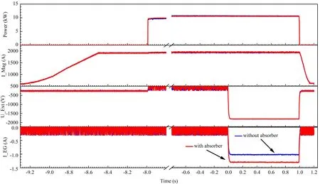
Figure 10.Trend of collected currents on EG (electron current) without/with the absorber.Data are taken at a pressure of 0.65 Pa and an RF power of 10 kW without cesium injection,a PG current of 1.9 kA and an extraction voltage of -1.8 kV.
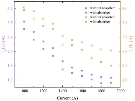
Figure 11.Results of co-extracted electron current and H- current without/with an absorber for different PG currents.Data are taken at a pressure of 0.5 Pa and an RF power of 75 kW with cesium injection,an extraction voltage of -6.3 kV and an acceleration voltage of -51 kV.
With the absorber ring applied,the increase of both EG current and H-current means that a reduced magnetic field at the driver exit could increase plasma outflow,thus increasing H-production through the ion production.
5.Conclusion and discussion
In order to reduce the charged particle loss on the driver walls and other structures,a simple device named an‘a(chǎn)bsorber’ was designed to decrease the magnetic field at the exit of the driver region.The soft iron absorber was proven to be effective at reducing magnetic flux density in the driver region in theories,simulations and experiments.The electron density that was measured before the PG,EG current and H-current all increased when the absorber was applied at the driver exit.Because there is no diagnostic port near the driver exit,the electron density cannot be studied in the driver exit.A new absorber is under consideration and will be installed for further performance studies on high power ion sources in the future.
Acknowledgements
This work was supported by the Comprehensive Research Facility for Fusion Technology Program of China (No.2018-000052-73-01-001228) and National Natural Science Foundation of China (No.11975264).
 Plasma Science and Technology2024年4期
- Plasma Science and Technology的其它文章
- A fringe jump counting method for the phase measurement in the HCN laser interferometer on EAST and its FPGA-based implementation
- Simulation of liquid cone formation on the tip apex of indium field emission electric propulsion thrusters
- Novel method for identifying the stages of discharge underwater based on impedance change characteristic
- Performance of pulsed plasma thruster at low discharge energy
- Dynamic propagation velocity of a positive streamer in a 3 m air gap under lightning impulse voltage
- On the evolution and formation of discharge morphology in pulsed dielectric barrier discharge
