Analysis of the characteristics of the plasma of an RF driven ion source for a neutral beam injector
Yongjian XU (許永建), Li ZHANG (張黎), Chundong HU (胡純棟),Yahong XIE (謝亞紅), Caichao JIANG (蔣才超), Jianglong WEI (韋江龍),Lizhen LIANG (梁立振)and Yuanlai XIE (謝遠(yuǎn)來)
1 Institute of Plasma Physics, Chinese Academy of Sciences, Hefei 230031, People’s Republic of China
2 Nuclear Power Institute of China, Chengdu 10213, People’s Republic of China
Abstract A radio frequency (RF) driven ion source is a very important component of a neutral beam injector for large magnetic confinement fusion devices.In order to study the key technology and physics of an RF driven ion source for a neutral beam injector in China, an RF ion source test facility was developed at the Institute of Plasma Physics,Chinese Academy of Sciences. In this paper,a two-dimensional fluid model is used to simulate the fundamental physical characteristics of RF plasma discharge.Simulation results show the relationship of the characteristics of plasma(such as electron density and electron temperature) and RF power and gas pressure. In order to verify the effectiveness of the model, the characteristics of the plasma are investigated using a Langmuir probe. In this paper, experimental and simulation results are presented, and the possible reasons for the discrepancies between them are given.This paper can help us understand the characteristics of RF plasma discharge, and give a basis for further R&D for an RF ion source.
Keywords: RF ion source, numerical simulation, neutral beam injection, inductive coupled plasma
1. Introduction
In order to bridge the gap between ITER and the fusion demonstration reactor(DEMO)and to realize fusion power in China, a new fusion facility (China Fusion Engineering Test Reactor,CFETR)has been developed and some key technical hurdles are being addressed [1-4]. Neutral beam injection is one of the most efficient means of four auxiliary plasma heating and has been applied to drive current in nuclear fusion physics studies [5-9]. For a simpler mechanical structure,convenient maintenance, and longer lifetime, RF driven ion sources have been selected as the preferred ion source for the CFETR heating neutral beam injector (NBI) [10-13].According to the latest physics design of CFETR, two NBIs,which deliver a total of 40 MW not less than 3600 s with 1 MeV D0, are needed to support the current drive and the plasma rotation. To minimize the risks and time to provide CFETR with reliable NBIs, a negative RF driven ion source test facility was developed in 2017 at the Institute of Plasma Physics, Chinese Academy of Science (ASIPP) [14-16]. Its mission is to understand the characteristics of the RF driven ion source,the generation and extraction of negative ions,and to improve the RF efficiency and beam quality. The main parameters of the negative RF driven ion source test facility are listed in table 1.Generally,the structure of an NBI RF ion source can be roughly divided into three parts:the cylindrical driver, the rectangular expansion chamber, and the extraction area. The RF plasma is generated by inductively coupled discharge which is produced by six-turn RF coils in the driver.The main function of expansion chamber is to reduce the electron temperature and the extraction area aims to extract plasma and form a high energy ion beam (see figure 1).
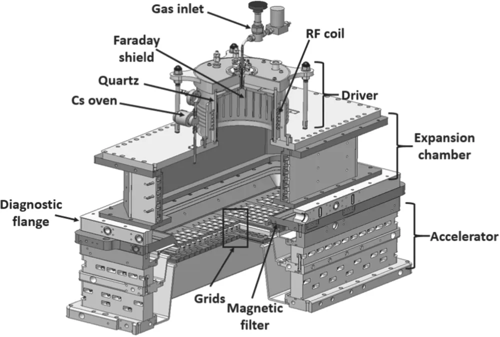
Figure 1.Three-dimensional diagram of the RF driven ion source.
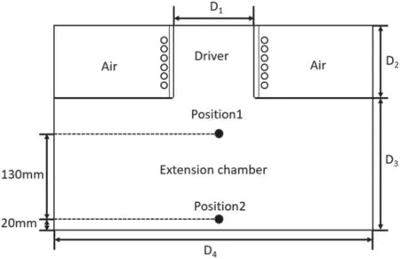
Figure 2.Simulation geometry of the RF ion source.
2. Simulation and analysis
Computer simulations are widely used to optimize the parameters of the designed ion sources, as well as to better understand ion production, extraction, and transport phenomena[17-20],so some simulations of the characteristics of the plasma of the RF ion source have been carried out.In the simulation,a two-dimensional(2D)fluid model is chosen and the variation trend of the electron density and temperature is given with increasing the gas pressure and RF power.
2.1. Simulation conditions of the model
A 2D schematic diagram of the inductive coupled plasma source is given in figure 2.The driver is a cylinder of diameter D1= 200 mm and height D2= 120 mm, and the dimension of the expansion chamber is 650 mm (L) × 260 mm(W) × 190 mm(H).Due to the the limitation of a 2D model,in order to keep the consistency between the simulation results and the actual structure, the shape of the expansion chamber is changed from a regular hexahedron to a cylinderaccording to the volume/surface ratio [21]. So, we chose D3= 190 mm and D4= 360 mm. Under these conditions,the volume/surface ratio of the experimental reactor (regular hexahedron) and the cylindrical model source are similar within less than 2%.The initial parameters are as follows:the working gas is hydrogen, the electron density is 1.0 × 10¹⁵m?3, the environmental temperature is 300 K, the average temperature is 5 eV, and the electron mobility is 4.0 × 1024m2· V?1· s?1. The particle species of the discharge gas mainly include H2molecules, H2+ions, and electrons. In the process of hydrogen gas discharge, the possibility of a reaction process mainly includes elastic collision,ionization,dissociation,excitation,and recombination.Table 2 gives the details of the reaction process [17, 21].
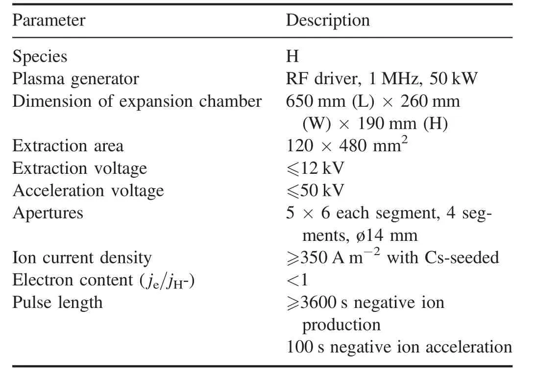
Table 1.The main parameters of the negative RF driven ion source test facility.
2.2. Simulation results and analysis
The aim of the simulation is to explore the distribution of the space of the plasma in the driver and expansion chamber and explain the operation of the RF ion source. So, the electron density, electron temperature, and plasma potential are simulated under the boundary and initial conditions mentioned above (see figure 3).
Figure 3 shows that (1) the peak of the electron density appears slightly above the center of the expansion chamber,(2) the peak of the electron temperature appears in the area close to the coil in the driver,(3)the spatial distribution of the plasma potential is similar to that of the electron density.
The discharge gas pressure and RF power are the key parameters which influence the plasma properties of an ion source.The electron density and temperature are investigated with different plasma discharge gas pressures and RF powers.Two key positions are selected for research in the simulation;the locations are at 150 mm(position 1)and 20 mm(position 2) above the center of the bottom of the extension chamber,respectively(see figure 2).According to figure 3,position 1 is in the area with the highest plasma density and position 2 is located in the extraction area and the electron density andtemperature in this area have a strong influence on the extracted current density of the negative ions.
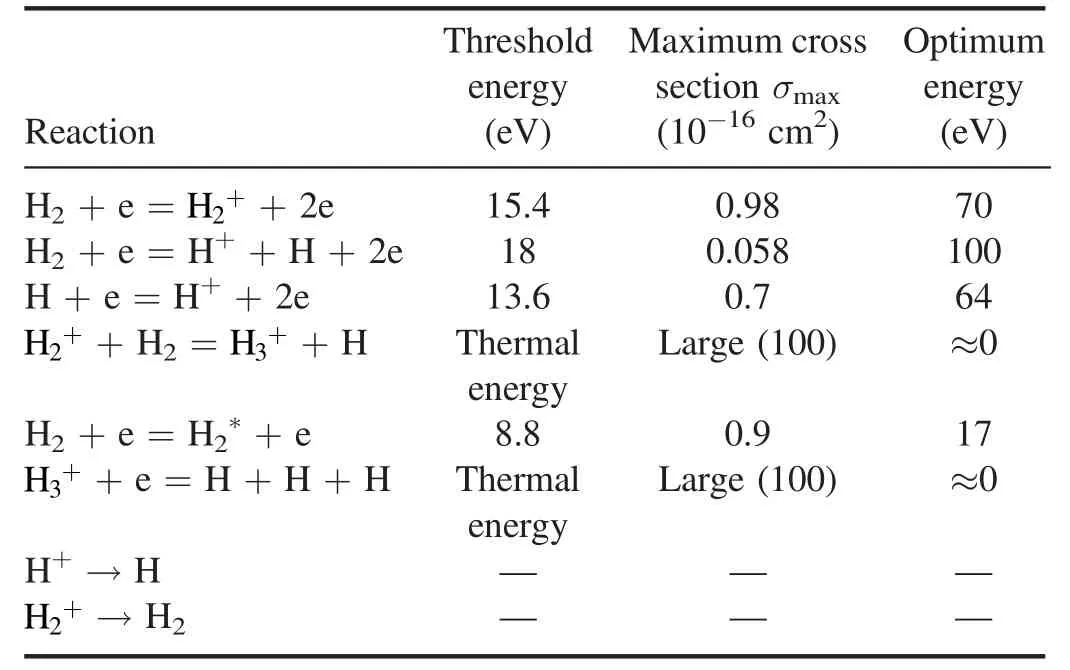
Table 2.The main reaction processes and values of the characteristics of various types of particles produced by hydrogen discharge (only part of the reactions are shown in this table).
RF power is one of the factors that determines the plasma parameters in the ion source. The magnitude of the induced magnetic field is affected by the RF power and the magnitude of the induced electric field is determined by the induced magnetic field, so the electron energy obtained from the electric field and ionization rate is closely related to RF power[22]. Figure 4 shows the variation trend of electron density and temperature with increasing RF power.
As can be seen from figure 4, the electron density increases approximately in line with increasing RF power.The reason is that with increasing RF power, the electrons obtain more energy from the induced electric field and a higher effective collision frequency resulting in a higher ionization rate. But the electron temperature remains approximately constant with the increase of RF power. A possible reason is that in the process of plasma diffusion the high energy electrons transfer their energy to the background particles through collisions, as the route is long enough to exhaust the energy of high energy electrons after multiple collisions, so figure 4(b) shows that the electron temperature is unrelated to the RF power.
Gas pressure is another key parameter for ion source operation, which has some influence on the plasma properties and stripping-loss during beam extraction. Therefore, a set of simulations is carried out to explore the relationship between electron density, electron temperature, and gas pressure. Figure 5 gives the variation trend of electron density and temperature with increasing gas pressure. It is shown that the electron density increases clearly as gas pressure increases(see figure 5(a)) and electron temperature decreases with the increase of gas pressure,especially below 1 Pa (see figure 5(b)). A possible reason is that the electron average free path decreases with increasing gas pressure and the collision frequency between electrons and nearby particle rises, so the ionization rate increases and more electrons are generated. A possible reason for the decline of electron temperature is that the particle density in the extension chamber rises with increasing gas pressure and the electron average free path decreases, resulting in the collision cross section between electrons and particles rises and a greater amount of electrons are used in ionization and excitation,so a drop in the electron energy leads to the decrease of the electron temperature [22]. These simulation results are consistent with the experimental results in other ion source test beds [23, 24].

Figure 4.(a) Electron density, (b) electron temperature as a function of RF power (gas pressure 2 Pa).
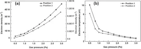
Figure 5.(a) Electron density, (b) electron temperature as a function of gas pressure (RF power 35 kW).
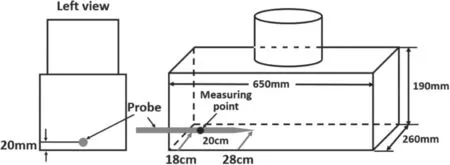
Figure 6.Schematic diagram of the installation position of the probe.
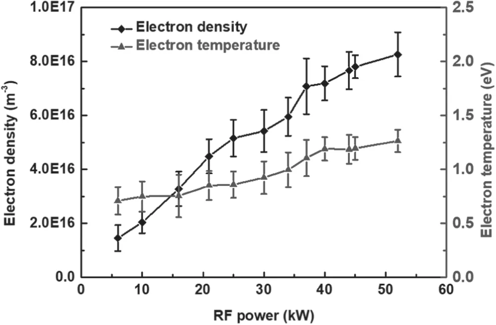
Figure 7.Electron density and temperature as a function of RF power (gas pressure 0.5 Pa).
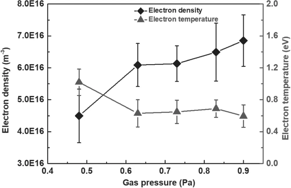
Figure 8.Electron density and temperature as a function of gas pressure (RF power 30 kW).
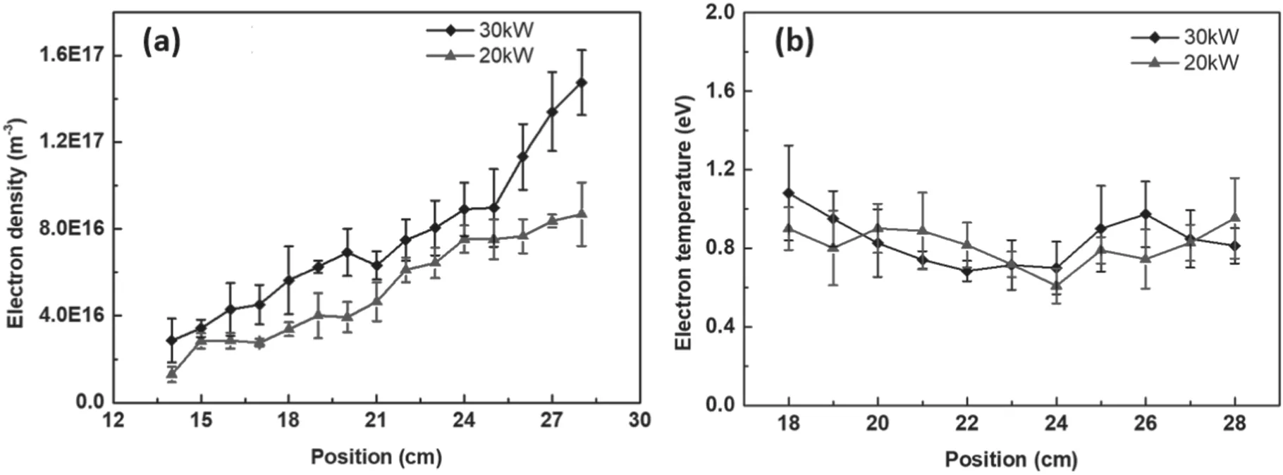
Figure 9.The spatial distribution of (a) electron density, (b) electron temperature at different RF powers (gas pressure 0.5 Pa).
3. Primary experimental results and discussion
In order to understand the spatial distribution of plasma and verify the validity of the model, the electron temperature and electron density are measured using a Langmuir probe(ESPion,British Hiden Analytical Ltd). The probe is installed in the diagnostic flange along the central line of the short side of the extension chamber and the distance between the probe tip and the bottom of the extension chamber is about 20 mm. (see figure 6).In order to assess the relationship between the plasma parameters and RF power,a fixed measuring point of a probe is set as 20 cm (scale of probe, see figure 6). In addition, the spatial distribution of electron temperature and electron density is also measured.Due to the limitation of the retractable scope of the probe, the measuring range is set from 18-28 cm.Figures 7 and 8 show the variation trend of the electron density/electron temperature with increasing RF power and gas pressure, respectively. The electron density increases and the electron temperature remains approximately constant with increasing RF power (see figure 7). Figure 8 shows that the electron density increases and the electron temperature decreases with increasing gas pressure. The variation trends are consistent with the simulation results except for the value of electron temperature. According to the simulation result, the value of the electron temperature is about 8 eV. A possible reason is that the magnetic field generated by the magnet filter(see figure 1)cools the electrons when the hot electrons diffuse from the extension area to the extraction area, so that the yield of negative hydrogen ion can be improved further [17].
The spatial distribution of electron density and temperature is also measured by the probe(see figure 9).Figure 9 shows that(1)the electron density increases when the probe is moved from 18 to 28 cm and the electron temperature almost remains constant; (2) the electron density at 30 kW is larger than that at 20 kW and the electron temperature is nearly the same at 20 and 30 kW. The variation trend is consistent with the simulation results presented in section 2. In order to overcome the shortcomings of the current Langmuir probe, a set of plane probes will be installed in the plasma grid and bias plate for measuring the plasma parameters in the extraction area.
4. Conclusion
Up to now,the negative RF driven ion source test facility has achieved a 50 kW stable long pulse plasma discharge at the 0.5 Pa gas pressure. In order to understand the plasma behavior, a set of simulations and experiments were carried out.The simulation results give the spatial distribution of the plasma and the relationship between electron density/temperature and RF power/gas pressure. Compared with the simulation results, a similar variation trend can seen in the experimental results. The results show that the electron density increases with increasing gas pressure/RF power and the electron temperature decreases with gas pressure, but almost remains constant when the RF power increases. These simulation and experimental results provide a foundation for cesium injection and beam extraction operation of an ion source in the future.
Some shortcomings in this work should be noted,such as the influence of the magnetic filter on the electron temperature,the scope of the Langmuir probe measurements,and so on. In future work, the drawbacks above will be eliminated one by one and the extraction of a H?beam will be carried out with Cs seed.
Acknowledgments
This work was supported by National Natural Science Foundation of China (Nos. 11675216, 11905248, 11975261,11975262, 11975263, and 11975264), the Key Program of Research and Development of Hefei Science Center,CAS (Contract No. 2016HSC-KPRD002) and the National Key R&D Program of China (Nos. 2017YFE0300101,2017YFE0300103, and 2017YFE0300503).
ORCID iDs
Lizhen LIANG (梁立振)https://orcid.org/0000-0002-5744-5727
 Plasma Science and Technology2020年2期
- Plasma Science and Technology的其它文章
- Synthesis of vertical graphene nanowalls by cracking n-dodecane using RF inductivelycoupled plasma-enhanced chemical vapor deposition
- Application of persulfate in low-temperature atmospheric-pressure plasma jet for enhanced treatment of onychomycosis
- Magnetic field enhanced radio frequency ion source and its application for Siincorporation diamond-like carbon film preparation
- Microwave frequency downshift in the timevarying collision plasma
- Comparison of Reynolds average Navier-Stokes turbulence models in numerical simulations of the DC arc plasma torch
- Effects of fast ions produced by ICRF heating on the pressure at EAST
