Dynamic propagation velocity of a positive streamer in a 3 m air gap under lightning impulse voltage
Zhiwei LI (李志偉),Ting LEI (雷挺),Yu SU (蘇宇),Xiuyuan YAO (姚修遠(yuǎn)),Bingxue YANG (楊冰雪),Delong LIU (劉德龍),Fangcheng LV (律方成) and Yujian DING (丁玉劍),*
1 North China Electric Power University,Beijing 102206,People’s Republic of China
2 China Electric Power Research Institute,Beijing 100192,People’s Republic of China
Abstract Streamers represent an important stage in the initiation of gap discharge.In this work,we used an eight-frame intensified charge-coupled device camera to capture the streamer development process when a lightning impulse voltage of 95%–100% U50% was applied in a 3 m rod–plate gap and the streamer velocity was analyzed.Analysis of the observations shows that streamer velocity can be defined by three stages: rapid velocity decline (stage 1),rapid velocity rise (stage 2)and slow velocity decline (stage 3).The effects of electrode shape,applied voltage and gap breakdown or withstanding on streamer velocity were analyzed.The electrode with a larger radius of curvature will result in a higher initial velocity,and a higher voltage amplitude will cause the streamer to propagate faster at stage 3.Gap withstanding or breakdown has no obvious effect on streamer velocity.In addition,the experimental results are compared with previous results and the statistical characteristics of the primary streamer discharge are discussed.
Keywords: lightning impulse,3 m air gap,development process,streamer velocity
1.Introduction
Discharge is a key and basic issue in the fields of high-voltage engineering and plasma research.The generation and development of streamers is an important stage in the gap discharge process [1–5].In-depth research into the microscopic mechanism of streamer discharge is helpful for improving the theory of gas discharge and reducing the thickness of the insulation during the design of power transmission and transformation equipment [6,7].Velocity is an important parameter in the development of streamers,so scholars have analyzed it by different methods.
In 1972,Les Renardières’ group reported some interesting findings concerning the developmental properties of streamers [8].They estimated the velocity of a streamer by analyzing the results from a streak camera and found that the streamer starts at a high velocity which then decreases because the local field decreases further down the gap.However,due to the limitations of the experimental conditions,only the trend of streamer velocity development was obtained and the estimated results are not accurate.
Grangeet al[9] measured the streamer velocity in a 1 cm rod–plate gap using a photomultiplier tube.When the applied voltage was 8 kV,the velocity decreased from the initial 0.5 mμs–1to 0.2 mμs–1with the development of the streamer.Wanget al[10] used a Blumlein pulse generator and a streak camera to study the development of positive and negative streamer discharges.When a positive voltage of 43–90 kV was applied,the streamer velocity was 0.8–1.2 mμs–1;when a negative voltage of 96 kV was applied,the streamer velocity was about 0.6 mμs–1.The accuracy of the above research results has been improved,but there is a lack of research under conditions of long gaps and multiple influencing factors.
In recent years,more and more researchers have adopted charge-coupled devices (CCDs) and intensified chargecoupled devices (ICCDs) to carry out related studies and obtain more accurate parameters.Wanget al[11] observed the development of streamer discharge in a wire-cylinder electrode using an ICCD camera.It was found that the maximum propagation velocity of the streamer discharge was 1.8–3.3 mμs–1at 72–91 kV and the field strength on the wire surface significantly affected the propagation velocity.Brielset al[12] used a CCD camera to observe the streamer in a point–plate air gap of length 4 cm and found that no streamers were generated for an applied voltage of less than 5 kV.The streamer velocity increased from 0.1 mμs–1to 4 mμs–1for an applied voltage of 5–96 kV.Moreover,the streamer velocity was greatly affected by voltage,voltage rise time and polarity.
Zeng and Chen [13] used 3a four-frame ICCD camera to study the dynamic velocity of a streamer in a 57 cm air gap under lightning impulse voltage.When the voltage amplitude was 250 kV,the streamer velocity decreased from 8.3 ±2.7 mμs–1to 0.4 ± 0.1 mμs–1under a hemispherical electrode.For different electrode shapes,the streamer velocity wasv(spherical)>v(hemispherical)>v(conical).Moreover,the streamer velocity increased with increasing rate of the voltage rise.References [14–19] have also demonstrated important progress in the simulation of the effects of applied voltage,background electric field,voltage polarity,electrode shape and experimental environment on streamer velocity.However,due to the restriction of experimental conditions,most studies on streamer discharge under lightning impulse were carried out in short air gaps with a length of several centimeters to tens of centimeters.There have been fewer experiments on streamer development in meter-scale long air gaps.Also,the scope of observations and studies cannot cover the whole process of streamer development.
In this work,an eight-frame ICCD camera was used to observe the dynamic development characteristics of a streamer in a 3 m rod–plate gap under lightning impulse.The influences of electrode shape,applied voltage and gap withstanding or breakdown on the streamer velocity are analyzed and compared with previous results.The relationships between the inception voltage and the peak current of the primary streamer discharge and the peak value of the impulse voltage are discussed.
2.Experimental setup and analytical method
2.1. Experimental setup
The experiment site is in Beijing (55 m above sea level),and a schematic diagram of the experimental layout is shown in figure 1.A positive lightning impulse voltage with a wavefront time of 1.3μs is generated by a 20-stage 6000 kV/900 kJ Marx generator.The rod–plate gap is 3 m in length.The hollow rod electrode is 1.5 m long with a measuring device placed inside,and the outer metal casing is insulated from the end electrode tip by an insulating layer to prevent the displacement current generated by the shielded casing from flowing through the measuring device via the electrode tip [20].The plate electrode is a 2 m × 2 m piece of galvanized iron sheeting.Two types of electrode tips were applied in the experiments,as shown in figure 1(b).One is a conical electrode tip with a bottom cross-section radius of 10 mm and a tip radius of 0.25 mm and the other is a hemispherical electrode tip with a radius of 10 mm.Under such experimental conditions,we haveU50%=1670 kV.
The image recording device of the experimental observation system is a SIMX8 ICCD camera.The SIMX8 has eight image sensor channels and can take eight photos in a row with a maximum image resolution of 1280 × 960 pixels.The interval between two adjacent frames can be set from 0 ns to 20 ms and the exposure time can be set from 3 ns to 10 ms.The above two parameters are independently variable between two adjacent frames and the minimum setting amplitude is 1 ns,so we can observe the dynamic development of the streamer more accurately.The voltage was measured by a capacitive voltage divider,and the voltage signal was captured by an oscilloscope.The current recording device,embedded in the rod electrode,mainly comprises a 2 Ω non-inductive resistor and a voltage recorder [20].The sample rate of the current measuring device was 100 MHz.When a lightning impulse current flows through the noninductive resistor,the voltage recorder collects the voltage signals at both ends of the non-inductive resistor and transmits them to the controller in the control room through the optical fiber.
When the oscilloscope receives the voltage signal,it immediately sends a trigger signal to the synchronous trigger DG645,which receives the trigger signal and synchronously triggers the image and current acquisition device.Meanwhile,the time delay of the cable,photoelectric conversion and other equipment that transmits the trigger signals should be taken into account.After synchronous calibration,the recording time errors of the image,voltage and current signals were controlled within 20 ns.As shown in figure 2(a),the synchronous observation system starts at time 0 and a current pulse appears at the instantI1,which is caused by the movement of charge carriers in the space at the beginning of the streamer discharge.This instant is identified as the initial time of the streamer.After a preset starting time delay,the ICCD starts shooting at the instantI2.Various color bands in the picture correspond to the shooting instants and exposure time of the ICCD.
2.2. Methods for analyzing streamer velocity
When the gap discharges,the atomic energy level transition in the streamer space produces photons.By utilizing an ICCD for shooting and setting different starting shooting instants,exposure times and shooting intervals for the experiments,and then integrating the results based on the development time,more comprehensive spatial motion characteristics of streamer development can be obtained.Figure 2(b)shows the projection of the streamer captured by an ICCD on a two-dimensional plane.The velocityvis calculated as the axial development distance Δyof the streamer between two adjacent frames divided by the time intervaltibetween two adjacent frames
It is worth noting that the exposure time of the ICCD in this experiment is mostly set at tens of nanoseconds,whereas the entire streamer development process takes about 3μs.So,it is necessary to adjust the ICCD’s settings in order to allow the calculated value to cover all stages of streamer development.The advantages of such a setting are that the trend of computing results will be more obvious and have a wider coverage of the timeline.However,the disadvantage is that the computational results are more scattered.At the same time,the wider gap in this experiment compared with previous ones will increase the dispersion of the streamer’s initial time,which also leads to a greater dispersion of the computed velocity results.The experimental results are therefore mostly described in scatter charts.
3.Experiments and results
3.1. Dynamic propagation velocity of streamers
Figure 3 shows the typical development of a streamer at different spatial ranges of observation and different time scales when 95%U50%is applied to the conical electrode.The streamer size is small during the initial stage of propagation.In order to improve the shooting accuracy at this stage,the focal length of the ICCD was adjusted to set the spatial range of observation to 0.4 m.In the later stage the streamer was about to penetrate the gap,and the experiment was repeated after the spatial range of observation was set to 3 m.
The relationship between streamer velocity and time is shown in figure 4.The figure is the result of integration of multiple sets of data under the same experimental conditions and different shooting modes.In our research,the streamer velocity is defined as having three stages.In stage 1 (initiation–0.88μs),the streamer velocity develops at a high initial value and then decreases sharply.The axial propagation velocity reaches the lowest value whent=0.88μs.The inset in the upper right of figure 4 shows the result in this stage zoomed in along the timeline.As the streamer develops very quickly during the first stage and is difficult to capture,it is not possible to obtain a stable initial velocity.In stage 2 (0.88–1.30μs) of streamer development,the streamer velocity increases sharply.Att=1.30μs,the velocity peaks at about 1.6 mμs–1.In stage 3 (1.30–3μs),the streamer velocity decreases slowly until it penetrates the gap.It takes the streamer about 3μs to develop onto the plate electrode.
Throughout the streamer development process,the velocity shows a trend of ‘declining rapidly,rising rapidly and then declining slowly’.Specifically,streamer development is fastest at the beginning and its velocity reaches its lowest value at the boundary of stage 1 and stage 2 (t=0.88μs).The streamer has the longest propagation time during stage 3,about 1.7μs.
Next,the above results are analyzed.Figure 5 shows the different stages of development of a streamer.As the streamer discharge region increases during stage 1,the electric field distribution gradually becomes uniform and the electric field in the streamer development area decreases,resulting in a rapid decrease in the streamer velocity.In stage 2,the rising voltage generates a high electric field around the anode and the secondary streamer discharge starts at a high initial velocity and continues to decrease until it converges with the primary streamer [21].During this stage,initiation of the secondary streamer enhances the electric field in the primary streamer head.Meanwhile,the increased electric field accelerates the propagation of the primary streamer,resulting in an increase in the measured value of the streamer velocity.In stage 3,the secondary streamer completely covers the primary streamer.Thereafter,there is no difference between the primary streamer and secondary streamer.The electric field distribution gradually becomes uniform and the streamer velocity gradually decreases.
3.2. Streamer velocity for different electrode shapes
As shown in figure 6,an interesting phenomenon was found when using different electrodes in the experiments.Different electrodes will lead to different streamer morphologies.In the experiment,a lightning impulse voltage of 100%U50%was applied.The exposure time was 20 ns at an observation space range of 0.3 m and 500 ns at an observation space range of 3 m.
It can be seen from the figure that the entire streamer discharge area under the two electrodes comprises a sector or a pyramid shape.In the early stage of development,the streamer under the hemispherical electrode with a bigger curvature radius has obvious branches,and its light trajectory has a needle shape.The streamer under the conical electrode with a smaller curvature radius has no obvious branches,and its light trajectory is in a dispersed state.At a late stage of development,the streamer morphology under both electrodes is dispersed and shows no significant difference within a 3 m observation space range.We will focus on those parts where there are differences in the initial stages of the streamer under the two electrodes.
Figure 7 shows the refined measurement results for the initial stage of a streamer under both electrodes.The figure integrates the refined measurement results of the initial stage velocity of the streamer under the same experimental conditions and different shooting modes.From the figure,it can be found that the streamer velocity under the hemispherical electrode starts rapidly and decreases rapidly;the streamer velocity under the conical electrode starts slowly and decreases slowly.Att=0.44μs,the streamer velocity is the same under both hemispherical and conical electrodes.
3.3. Streamer velocity in the case of gap withstanding and breakdown
Figure 8 shows the variation of streamer length and velocity with time for gap withstanding and breakdown under the same conditions att=0.4–1.8μs.The figure shows the results of a single shot,where the linear plot is the length of streamer development and the scatter plot is the streamer velocity.It can be observed that the values and trends for streamer development length and velocity do not differ much in the two cases.
Att=1.196μs,the difference in development length is the largest at about 5.2 cm;att=1.118μs,the velocity difference is the largest at about 0.705 mμs–1.Therefore,it can be inferred that there is no significant effect on streamer velocity for gap discharge withstanding or breakdown.
3.4. Streamer velocity under different voltages
Figure 9 shows the variation of streamer velocity when different voltages are applied.The figure contains the integrated results of multiple sets of data under the same experimental conditions and different shooting modes.The difference between the velocity of the streamer when 95%–100%U50%was applied is not significant in stages 1 and 2.In stage 3,the higher the applied voltage,the faster the streamer develops.Att=2.25μs,the velocity under 100%U50%is about 0.25 mμs–1higher than that under 95%U50%.
4.Discussion
4.1. Comparison with previous findings
In this section,our experimental results are compared with the typical results of previous work.Morrow and Lowke [22]obtained a positive streamer development law in a 50 mm point–plane gap at an applied voltage of 20 kV by means of simulation.Based on their simulation results,the streamer velocity was divided into three stages: rapid streamer propagation (6–40 ns),slow streamer propagation (40–130 ns) and streamer termination (130–210 ns).In our experiment,the streamer velocity is defined as comprising three stages based on measured and calculated results: rapid velocity decline(stage 1,initiation–0.88μs),rapid velocity rise (stage 2,0.88–1.30μs) and slow velocity decline (stage 3,1.30–3.00μs).Compared with the simulation results of Morrow and Lowke,our experiment uses a high-precision ICCD to observe the process of streamer velocity recovery when a positive lightning impulse voltage is applied.
Zeng and Chen [13] studied streamer discharge development in a 0.57 m rod–plate gap at an experimental voltage amplitude of 250 kV.For hemispherical and conical electrodes,the streamer velocity decreased rapidly from 3.2 mμs–1to 0.80 mμs–1in 50 ns and from 1.7 mμs–1to 0.5 mμs–1in 60 ns,respectively.In our experiment,the process of development of a 3 m rod–plate gap streamer was studied.When a voltage of 1670 kV was applied to the hemispherical and conical electrodes,the streamer velocity decreased rapidly from 4.8 mμs–1to 0.80 mμs–1in 0.25μs and from 3.5 mμs–1to 0.5 mμs–1in 0.4μs,respectively.The results of this study and previous studies show that,compared with a conical electrode,a hemispherical electrode has a faster initial velocity and a greater falling rate.
Brielset al[12] at TU/e University studied streamer development at a 0.04 m point–plane gap.The applied voltage was increased from 5 kV to 96 kV,and the streamer velocity increased from 0.1 mμs–1to 4 mμs–1.In Creyghtonet al’s experiment [23],the streamer velocity increased from 2 mμs–1to 3.5 mμs–1when a pulse voltage of 20–25 kV was applied.The present experimental measurements found that the higher the applied voltage at stage 3 the faster the streamer velocity when applying 95%–100%U50%.Hence,a higher voltage amplitude leads to a greater velocity.References [24–26] also obtained the same results through experiments and simulations.
The voltage rise rate is another important factor affecting streamer velocity.Komuroet al[27] simulated that when the applied voltage of a 13 mm rod–plate gap was 24 kV and the voltage rise rates were 0.11 kV ns–1and 0.52 kV ns–1,the average streamer velocities were 0.49 mμs–1and 0.69 mμs–1,respectively.Winandset al[28] found that when the voltage rise rate increased in the range of 1.5–2 kV ns–1,the streamer velocity increased from 0.5 mμs–1to 2.5 mμs–1.In our experiment,the voltage rise rates were 1.22 kV ns–1and 1.28 kV ns–1,and the average streamer development velocities were 0.9 mμs–1and 1 mμs–1,respectively.Yagiet al[29]and Yoshinagaet al[30] also did a similar study and concluded that the propagation velocity of the streamer heads increased with a higher rise rate of the applied voltage.
It should be noted that although the initial streamer velocity in this experiment is large,this value is underestimated due to the limitations of the experimental equipment and methodology.In future research,we aim to extend the experiment to extreme environments such as high altitude and low temperature.At the same time,we will explore the universal model of streamer propagation based on the existing data and known influencing factors to obtain a more accurate picture of dynamic streamer development.
4.2. Statistical characteristics of the primary streamer discharge
In this work,the statistical characteristics of the primary streamer discharge were analyzed for lightning impulse voltages of 90%U50%,95%U50%and 100%U50%(U50%=1670 kV;the experiment applying 90%U50%was a supplementary experiment).Figures 10–12 show the integrated results for multiple sets of data under the same experimental conditions.
Figure 10 shows the relationship betweenui,the inception voltage of the primary streamer discharge,andthe peak value of the impulse voltage.In this figure,the data points represent the results of each experiment and the line segments represent the linear fitting values forui.The statistical results were aggregated into three groups.Regardless of the voltage range,uishows a dispersion
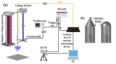
Figure 1.(a) Simultaneous observation systems.(b) Conical electrode tip and hemispherical electrode tip.
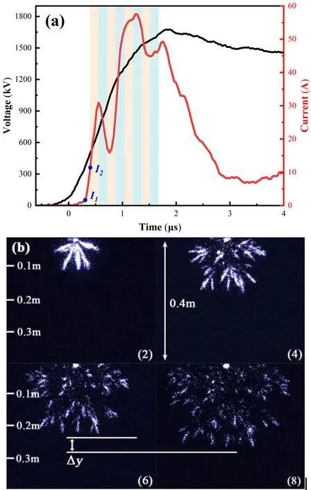
Figure 2.(a) Voltage and current waveforms and ICCD operating states in a 3 m rod–plane gap at 100% U50% (synchronous observation system starting time 0 μs,ICCD starting time 0.396 μs,exposure time 0.16 μs).(b) The second,fourth,sixth and eighth images captured by the ICCD in figure 2(a).
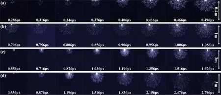
Figure 3.Typical development of a streamer under different observation spaces and time scales when 95% U50% is applied to a cone electrode: (a) observation space 0.4 m,exposure time 30 ns;(b) observation space 1 m,exposure time 50 ns;(c) observation space 3 m,exposure time 160 ns;(d) observation space 3 m,exposure time 160 ns.The shooting interval is 160 ns.
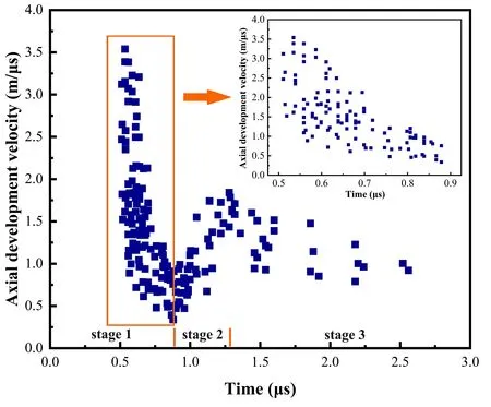
Figure 4.Dynamic development of streamer velocity.The time zero is the start time of the synchronous observation system.
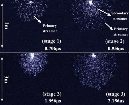
Figure 5.The different stages of development of a streamer.
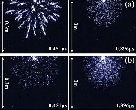
Figure 6.Comparison of streamer development morphology for different electrode shapes.The applied voltage is 100% U50%: (a)hemispherical electrode and (b) conical electrode.
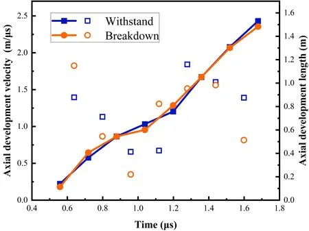
Figure 8.Variation of streamer length and velocity with time in the case of gap withstanding and breakdown (cone electrode,95%U50%).
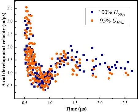
Figure 9.Variation of streamer velocity when 100% U50% and 95%U50% are applied to a cone electrode.
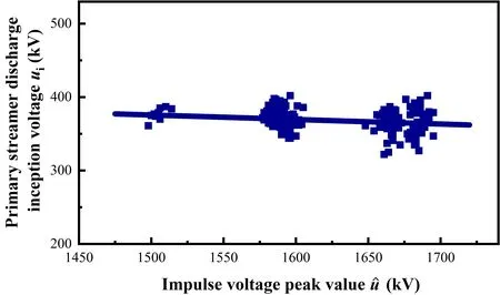
Figure 10.Relationship between the inception voltage of the primary streamer discharge and the peak value of the impulse voltage (correlation coefficient R2=0.036).
It can be seen from the statistical results that the discharge inception voltageuiof the primary streamer and the deviation of inception voltage δuiremain approximately constant;the average inception voltageis almost independent of the peak value of the impulse voltageWith increase in the statistical samples,shows minor statistical changes.
Figure 11 shows the relationship between the peak currentipof the primary streamer and the peak value of impulse voltage.Although there is still dispersion,it is obvious thatipincreases with increase in
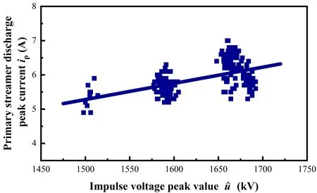
Figure 11.Relationship between the peak current of the primary streamer discharge and the peak value of the impulse voltage(correlation coefficient R2=0.34).
Equation (3) is the fitting result of a linear function.Due to the influence of data dispersion,it is difficult to obtain definite values fork1andk2.Statistical studies have found that the value range ofk1is [0.004881,0.006942] and that ofk2is [-5.392,-2.017].The fitted curve in figure 12 uses the optimal values of both,withk1=0.005912,k2=-3.705.
Figure 12 shows the relationship between the peak current valueipand the discharge inception voltageuiof the primary streamer.It can be seen that there is no obvious correspondence betweenipandui.
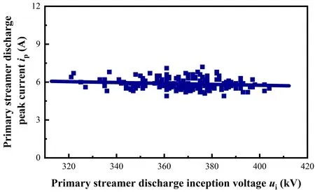
Figure 12.Relationship between the peak current value and the inception voltage of the primary streamer discharge (correlation coefficient R2=0.014).
5.Conclusions
In this paper,an experimental study of positive streamer discharge in a 3 m rod–plate gap under lightning impulse voltage is described.Based on an ICCD synchronous observation system,the dynamical development of a streamer in the range of 0.3–3.0 m is obtained.The following conclusions are obtained from analyzing the experimental results:
(1) When 95%–100%U50%is applied to the two types of electrodes,the streamer velocity shows three stages: rapid velocity decline (stage 1),rapid velocity rise (stage 2) and slow velocity decline (stage 3).
(2) The influence of the electrode on streamer development is studied.When a hemispherical electrode is used,the streamer form gradually evolves from a needle shape at the initial stage to a state of dispersion.When a conical electrode is used,the streamer shows a state of dispersion throughout the development process.The initial streamer velocity of the hemispherical electrode is fast and the falling rate is high,while the initial streamer velocity of the conical electrode is slow and the falling rate is low.
(3) Gap withstanding or breakdown has no obvious effect on streamer development.In addition,when a 100%U50%positive lightning impulse voltage is applied,the streamer velocity is faster than that when 95%U50%is applied in stage 3,but the difference is not obvious in stages 1 and 2.
(4) The statistical characteristics of the primary streamer discharge are discussed.There is no obvious correspondence between the inception voltage and the peak current of the primary streamer discharge or the peak impulse voltage.The peak current of the primary streamer discharge is positively correlated with the peak impulse voltage.
Acknowledgments
This work was supported by the Beijing Science Fund for Distinguished Young Scholars (No.JQ22009) and National Natural Science Foundation of China (No.51977198).
——煩心事也能『幽它一默』
 Plasma Science and Technology2024年4期
- Plasma Science and Technology的其它文章
- Experimental results of a magnetic field modification to the radio frequency driver of a negative ion source
- A fringe jump counting method for the phase measurement in the HCN laser interferometer on EAST and its FPGA-based implementation
- Simulation of liquid cone formation on the tip apex of indium field emission electric propulsion thrusters
- Novel method for identifying the stages of discharge underwater based on impedance change characteristic
- Performance of pulsed plasma thruster at low discharge energy
- On the evolution and formation of discharge morphology in pulsed dielectric barrier discharge
