Understanding the effects of electrode meso-macropore structure and solvent polarity on electric double layer capacitors based on a continuum model
Haotian Lu ,Jinghong Zhou *,Yueqiang Cao ,Tongxin Shang ,Guanghua Ye ,Quan-Hong Yang2, ,Xinggui Zhou
1 State-Key Laboratory of Chemical Engineering,East China University of Science of Technology,Shanghai 200237,China
2 Joint School of National University of Singapore and Tianjin University,International Campus of Tianjin University,Binhai New City,Fuzhou 350207,China
3 Nanoyang Group,State Key Laboratory of Chemical Engineering,School of Chemical Engineering and Technology,Tianjin University,Tianjin 300350,China
Keywords:Electric double layer capacitors Numerical simulation Meso-macropore Electrolytes Saturated dielectric permittivity
ABSTRACT The structures of electrode meso-macropore and the solvent polarity are the crucial factors dominating the performance of the electric double layer capacitors(EDLCs),but their impacts are usually tangled and difficult to decouple and quantitate.Here the effects of electrode meso-macropore structure and solvent polarity on the specific capacitance of an EDLC are quantitatively investigated using a steady-state continuum model.The simulation results indicate the specific capacitances are significantly affected by the meso-macropore surface structure.The specific capacitances significantly decrease for both convex surface structures but obviously increase for both concave surface structures,with the increase of curvature radius from 1 to 20 nm.As for solvents,the polar solvent with high saturated dielectric permittivity improves the capacitance performance.Moreover,the electrode meso-macropore structure is of more concern compared with solvent polarity when aiming at enhancing the specific capacitance.These results provide fundamentals for the rational design of porous electrodes and polar electrolytes for EDLCs.
1.Introduction
Electric double layer capacitors (EDLCs) have been increasingly attractive as electrical energy storage devices for their advantages of high power densities,fast charging-discharging capability and long cycling life over batteries.Basically,energy is stored in EDLCs through reversible electrostatic adsorption of ions on the interface of electrode material and electrolyte.There is no faradic reaction in EDLCs,which restricts their charge storage capacity and leads to the lower energy densities of EDLCs compared with batteries[1,2].Although EDLCs have been applied in some electric vehicles,such as hybrid buses,their relatively low energy density could not satisfy the industry requirements so far and prevent them from wider application.Therefore,numerous efforts have been made both in industry and in academia to enhance their energy densities which depend on specific capacitance and operating voltage window.
As for improving specific capacitance,one of the effective ways is to develop nanostructured electrode materials [3-9],among which carbon materials,offering good conductivity,electrochemical stability,and large specific surface area,are the most promising candidate.Since the charge storage relies on the interface of electrode material and electrolyte,carbon materials with different nanostructures have been explored to enhance their specific surface area and thus maximize the specific capacitance per unit mass(or unit volume)[10,11].For example,onion-like carbon,the zerodimensional nanoparticle of 5-15 nm,exhibited a specific surface area of less than 600 m2·g-1and a limited capacitance of 30 F·g-1[6].Single-walled carbon nanotube,nonporous one-dimensional nanomaterial,presented a specific surface area up to 1000 m2·g-1and capacitance ranging from 50 to 70 F·g-1[7].Graphene-based carbon material was preparedviareduction of graphite oxide as two-dimensional material and had a specific surface area of 1310 m2·g-1and a quite good capacitance up to 247 F·g-1[8].Finally,activated carbon,as the conventional carbon material,commonly used for EDLCs electrode,possessed abundant micropores and mesopores forming a three-dimensional porous network with a specific surface of 820 m2·g-1and a fair specific capacitance of 91 F·g-1[9].These results demonstrate that the specific capacitance of EDLCs is not only related to the specific surface areas but also affected by the micro-meso-macroporous structures of the carbon materials.For example,some experimental and simulation results have shown that the micropores are mainly full of desolvated ions and the capacitance could be strongly influenced by atomic-scale roughness or curvature in the micropores[12-16].In fact,the meso-macropores in or between carbon materials using the electric double layer to store energy also play important role in providing capacitance,especially working with high current densities which make it difficult for ions to enter micropores.However,the structure of meso-macropores inside electrode includes different aspects:the shape of nanoparticles,the particle size and distribution and the shape and size of particle internal pores.All these aspects of meso-macropore structure would definitely affect the capacitance of EDLCs in a complicated way and the contribution from each aspect is entangled with that from one another.Therefore,how the structure of electrode meso-macropores affects the performance of EDLCs still remains unclear [17,18].
Apart from enhancing specific capacitance,another effective approach to increase the energy density of EDLCs is to increase the operating voltage window.In this respect,nonaqueous electrolytes,usually consisting of an organic solvent and a salt,such as tetraethylammonium tetrafluoroborate(TEABF4)in methyl cyanide (MeCN) or propylene carbonate (PC) [19,20],have been recently proposed as more stable under high potential and could provide wider voltage window as 2.5-2.8 V [21,22],Previous research showed that the specific capacitance of EDLCs is proportional to the zero-field relative dielectric permittivity which is in positive correlation with the polarity of the solvent [23].Several solvents with high polarity have been thus explored to apply in the electrolyte system for the EDLCs and displayed good electrochemical stability at a wide potential window [24].So far,some studies have also shown that solvent polarity plays an important role in the solvation and desolvation of ions in the electrochemical energy storage process [25].While,the role of the polarity of solvent in the working mechanism of the EDLCs during the charge storage process still needs to be elucidated [21,25].
Immense amounts of experimental research on the performance of EDLCs with the porous electrode and organic electrolytes have achieved some consistent conclusions that large surface area,the appropriate pore/particle size and organic solvents with high relative dielectric permittivity could improve the energy density of EDLCs.However,these qualitative results could not provide adequate fundamentals for the rational design of EDLCs,including the carbon material with proper nanostructure and the corresponding electrolytes.Mathematical modelling of EDLCs,which simplify and describe the system mathematically and could make quantitative analysis and optimization,thus,could be an appropriate option to get insight into the working mechanism of EDLCs and elucidate the impact of the meso-macroporous structure of electrode as well as the polarity of electrolyte.
There are several mathematical models for modelling the EDLCs,such as the equivalent resistor-capacitor(RC)circuit model[26,27],the molecular dynamics model (MD) [12-14,17,18,28],and the continuum model[29-31].The equivalent RC circuit models are built to simulate the EDLCs as an electrical device in an energy storage process and cannot provide the working mechanism inside the EDLCs for the rational design of electrodes[26,27].The MD models usually are used to explore the interaction mechanism of ions,solvents and carbon materials at the atomistic/molecular level,but require high computation power to simulate complex electrode structures and electrolytes (such as different pore structures and realistic solvents and salts) in EDLCs[12-14,17,18,28].The continuum models,which are built based on the physical principle of the charge storage in the electric double layer,seem to be a credible and efficient compromise to describe the reversible electrostatic adsorption of ions in mesomacropores full of the electrolyte and provide useful information both on the working mechanism of EDLCs and on the performance optimization [29-31].
After years’ development,the continuum models have evolved from the basic Helmholtz double layer model,the Gouy-Chapman double layer model to the Gouy-Chapman-Stern double layer model [30].Most recently,Wanget al.[32] have developed a continuum model based on the Gouy-Chapman-Stern model to describe the ion concentration and electric potential distribution inside the electric double layer and successfully predicted the specific capacitance.Note that the continuum model can account for details of the actual electrode spatial structures and electrolyte dielectric permittivity.To the best of our knowledge,the simultaneous influences of electrode meso-macropore structure and the organic solvent with different polarities on the capacitance performance of EDLCs,especially using the continuum model to quantify the impact,have not been studied hitherto.
Therefore,in this work,we intend to present a more detailed investigation into both effects of electrode meso-macropore structures and organic electrolyte properties on the energy densities of EDLCs,based on a steady-state double layer continuum model.The specific surface capacitances are numerically predicted and analyzed for carbon materials of different nanostructures (particle/pore morphology and size) in different organic electrolytes.The results in this work will provide useful strategies for optimizing the design of electrode porosity and organic electrolyte for EDLCs.
2.Modelling
2.1.Schematics of meso-macropore surface structure
The actual meso-macropores of carbon electrode are composed of pores of different sizes inside/among the nanoparticles of different sizes [5].And EDLCs store charges by adsorbing ions at the interfaces of carbon material and electrolyte,which means ions are adsorbed on the surfaces of particles and/or pores.Although the spatial structures of electrode meso-macropores are diverse and quite complex,the whole electrode is isopotential under an equilibrium condition,namely,the electric potentials at the surfaces of different carbon nanostructures are identical.Thus,we could simplify the diverse structures of the meso-macropore in the electrode into five typical surface structures as: (1) concave spherical surface (CCSS),(2) convex spherical surface (CVSS),(3) concave cylindrical surface (CCCS),(4)convex cylindrical surface (CVCS),and (5) flat surface (FS).They represent the real surfaces where ion adsorption occurs for (1)the interface of spherical pore and the electrolyte,(2) the interface of spherical nanoparticle and the electrolyte,(3) the interface of cylindrical pore and the electrolyte (like the internal surface of the carbon nanotube),(4) the interface of cylindrical carbon material (like the outside surface of carbon nanotube)and the electrolyte,(5) the interface of plate carbon material and electrolyte (like graphene surface),respectively.The schematics of five surface structures are shown in Fig.1(a).Here,the curvature radius (R0) rather than the pore diameter is used to represent the pore morphology and pore size.For example,the cylindrical mesopore with diameters between 2 and 50 nm have the curvature radius of 1-25 nm.This simplification would allow us to easily simulate the work of EDLCs and further investigate accurately the effects of the spatial structures of electrode meso-macropore as well as their curvature radius on the performance of EDLCs.
2.2.Model description and assumption
Fig.1(b) shows the electric double layer structure and the dielectric permittivity distribution near the interface of electrode meso-macropore and electrolyte.The Gouy-Chapman-Stern model is employed to describe the electric double layer structure [33].Here,the electric double layer is divided into two parts existing in the electrolyte,namely,(1) the Stern layer where immobile counterions strongly adsorb to the interface of carbon material and electrolyte,the thickness of the stern layer is expressed asH=a/2,andais the diameter of counterions,and (2) the diffuse layer where the ions could transfer under the combined effects of diffusion and electrostatic forces.It is worth noting that there are no free charges within the Stern layer.
The electric potential is supposed as positive at the interface and zero where far away from the interface[34].The overall computational region consists of the Stern layer and the diffuse layer.The length of the diffuse layer is specified asL=100 nm for all computational cases,for our preliminary computation results indicated that further increasing the length of the diffuse layer,for example,to 200 nm,would not change the predicted specific surface capacitance.
In order to easily solve the mathematical model,the dielectric permittivity of electrolytes was assumed as constant in the previous simulation research[31],but in fact the relative dielectric permittivity of polar solvents significantly decreases when the electric field increases [35].Therefore,in this work,the electrolyte dielectric permittivity is expressed as a function depending on electric field.
To make the problem mathematically more tractable,the following assumptions are made: (1) the electric potential and ion concentration are independent with time and have reached their equilibrium states [36];(2) the electrode is in isopotential state,since there is no electric current under equilibrium;(3)isothermal conditions prevail throughout the electrode and electrolyte;(4)the ions could not diffuse into the solid phase of carbon material,which only accumulate at the carbon material surface;(5) anions and cations have the same effective diameter independent of the electrolyte concentration [37];(6) the specific ion adsorption due to non-electrostatic forces are assumed to be negligible,i.e.,there is no functional group produced by material modification;(7)because the relative permittivity is typically defined based on the solvent molecule with characteristic length,which is larger than the thickness of Stern layer [35,38,39],it is reasonable to assume the relative dielectric permittivity within the Stern layer is constant.
2.3.Governing equation
The modified steady-state governing equations based on Wang’s continuum model [32] are employed to describe the electric double layer within meso-macropore.The major modification we made to Wang’s continuum model is to assume the relative dielectric permittivity within the Stern layer is constant,which simplifies the calculation.Based on the assumption (2) and (4),the governing equations only need to be solved within the diffuse layer of electrolyte solution.The local equilibrium electric potential in the diffuse layer,denoted by ψ(r),can be determined by solving the Bikerman’s Modified Poisson-Boltzmann (BMPB) model accounting for the finite size of the ions[40].And the BMPB model is expressed as [37,41],

Here,ε0and εrare the free-space dielectric permittivity and the relative dielectric permittivity of electrolytes,respectively.eis the elementary charge,NAis the Avogadro constant,andkBis the Boltzmann constant.The valence of the symmetric electrolyte is denoted byz.c∞is the bulk molar concentration of electrolytes,andTis the absolute temperature.The packing parameter,denoted by v=2a3NAc∞,represents the ratio of the total bulk ion concentration to the maximum ion concentrationcm=1/NAa3assuming a simple cubic ion packing.Therefore,v could not be larger than 1 for the model to be physically acceptable.
The relative dielectric permittivity of organic solvent in the electric field,denoted by εr(E),can be determined by solving the Booth model which accounts for the dependency of electrolyte dielectric permittivity on the local electric field larger than 107V·m-1[32,42],

While εrcan be treated as constant for the local electric field lower than 107V·m-1,


Fig.1.(a) Schematics of the five typical surface structures of electrode meso-macropore: (1) CCSS,(2) CVSS,(3) CCCS,(4) CVCS and (5) FS.(b) A schematic of the electric double layer structure and the dielectric permittivity distribution near the electrode/electrolyte interface.
Here,E=|-?ψ| is the norm of the local electrical field vector,nis the index of refraction of the electrolyte at zero electric field frequency,εr(0)is the relative dielectric permittivity at a zero electric field,and β is a fitting parameter.
2.4.Boundary conditions &relevant parameters
To solve Eq.(1) for the potential ψ(r)and the relative dielectric permittivity εr(E)in the diffuse layer,two boundary conditions are required at the interface of the Stern layer and diffuse layer(r=0) and away from the interface (r=L).Wang’s generalized boundary conditions for different surface nanostructures are used in this work to determine the boundary condition atr=0[35,42].These boundary conditions atr=0 are expressed as:
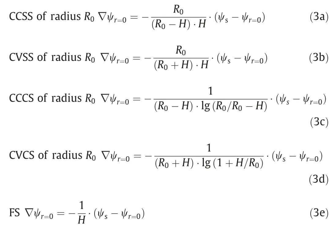
Here,His the thickness of the Stern layer and can be approximated as the effective radius of the ions.
The boundary condition atr=L,as the electric potential is zero far away from the interface of Stern layer and diffuse layer,thus is expressed as

The zero-field dielectric permittivity εr(0)is commonly used to classify the polarity of solvent[35].Therefore,four commonly used solvents in EDLCs whose zero-field dielectric permittivity spanning from 2.49 to 106.6 are investigated in this work,including ethylene carbonate (EC),PC,MeCN and dimethyl carbonate (DMC).Their property change within the electric field is represented by the variation in the relative dielectric permittivity εr(E).The parameters of these organic solvents for the Booth model are given in Table 1.

Table 1 The parameters of organic solvents for the simulations in this work
In order to solve Eq.(1),(2a)and(2b),along with the boundary conditions given by Eqs.(3a)-(3e)and Eq.(4),the electrolyte propertiesz,c∞,aand the temperatureTare needed.The typical binary electrolyte used in EDLCs devices is TEABF4,and the electrolyte concentrationc∞is 1.0 mol·L-1[19,20].The binary electrolyte TEABF4in organic solvents at room temperature is characterized by the following properties:z=1.Unless otherwise specified,the effective diameters of TEA+andions is calculated according to the size of bare ions,and their diameters are assumed to be equal and constant in our simulation,i.e.,the diameter of bare iona=0.68 nm and the diameter of solvated iona=1.30 nm[43,44].Finally,the temperature is taken as room temperatureT=298 K.The potential of electrode is ψs=1 V.
2.5.Method of solution and data processing
Eq.(1),Eq.(2a) and Eq.(2b) are solved using the commercial finite element solver COMSOL 4.3,along with the boundary conditions given by Eqs.(3a)-(3e)and Eq.(4),respectively.Mesh refinement is required near the Stern/diffuse layer interface where the potential gradient is the largest.Moreover,the numerical convergence is assessed based on the maximum relative difference in the local electric potential at the Stern/diffuse layer interface.It can be regarded as convergence that the deviation is less than 1%when the total number of finite elements is multiplied by two.The total number of finite elements is on the order of 106for the simulations of all cases in the present study.The simulations are run on a Dell computer XPS 8910-R15NB with a 2400 MHz Quad-Core i5-7400 CPUs and 8 GB of RAMs.
The total chargeQstored at the carbon material surfaceAsis determined by integrating the surface charge density,ε0εr(E)E·n,along with the interface of carbon material and electrolyte,and is expressed as [34,45]

where E=-?ψ is the electric field vector,n is the local outward normal unit vector at the carbon material surfaceAs.Then,the diffuse layer specific surface capacitanceand the total specific surface capacitanceCsare respectively expressed as [32,34]

where ΔψDand Δψsare the potential differences of Stern layer/diffuse layer interface and bulk electrolyte,and that of the electrode surface and bulk electrolyte,respectively.And the Stern layer specific surface capacitanceshould be estimated for different surface nanostructures,and they have been derived in Ref.[36] and are expressed as

3.Results and Discussion
3.1.Effects of electrode meso-macropore structure
Using the mathematical model established in Section 2,we have calculated the specific surface capacitance for the five surface structures of meso-macropore at different surface curvature radius under the selected four solvents with different polarities.The numerically predicted specific surface capacitances of Stern layer,diffuse layer,and totalCsas a function of curvature radiusR0ranging from 1 to 60 nm with electrode immersed in the TEABF4/EC,TEABF4/PC,TEABF4/MeCN and TEABF4/DMC electrolyte have been obtained.The results for different electrolytes follow a similar pattern.Thus,for simplicity,only the results with EC as a solvent are presented in Fig.2.The other results could be found in Figs.S1-S3 (in Supplementary Material).
As can be seen in Fig.2,is much smaller thanfor any type of surface nanostructures,thusCsis mainly dominated by theaccording to 1/Cs=1/+1/.This conclusion is in good agreement with other researchers although they only verify it with TEABF4/PC electrolyte[32].The fact that the Stern layer dominates the total capacitance of the EDLCs is due to the smaller relative dielectric permittivity within the Stern layer compared with that within the diffuse layer,which will be discussed further in Section 3.2.
Fig.3 shows the numerically predicted total specific surface capacitance as a function of curvature radius ranging from 1 to 60 nm for CCSS,CVSS,CCCS,and CVCS structures immersed in different electrolytes.The curvature radius of FS is infinite,namelyR0→∞,and the specific surface capacitance of FS structure is a constant value for each given solvent.Thus theCsvariation with the curvature radius for FS structure in Fig.3 is a horizontal line.As seen in Fig.3,the total specific surface capacitances are significantly affected by curvature radius and surface structure for different electrolytes.
For convex surface structures(CVSS and CVCS),the total specific surface capacitanceCsdecreases considerably with curvature radiusR0.WhenR0is smaller than 20 nm,the total specific surface capacitanceCsis higher than that of the FS structure for a given electrolyte.Especially,Csis much higher whenR0is less than 4 nm.On the contrary,for concave surface structures (CCSS and CCCS),the total specific surface capacitanceCsincreases considerably with curvature radiusR0and is lower than that of the FS structure for a given electrolyte whenR0is smaller than 20 nm.Especially,Csis much lower whenR0is less than 4 nm.
Moreover,for cylindrical surface structures (CVCS and CCCS)with a curvature radiusR0larger than 20 nm,the total specific surface capacitanceCsremains nearly unchanged with curvature radius (variation is less than 1% of the total specific capacitance of FS structure).And for spherical surface structures (CVSS and CCSS)with curvature radiusR0larger than 40 nm,the total specific surface capacitanceCsremains nearly unchanged under different curvature radius (variation is less than 1% of the total specific capacitance of FS structure).These results indicate that when the particles or pores are large enough,theCsof their surfaces (either external surface or internal surface) are equal to that of FS structure and the morphology does not matter anymore.
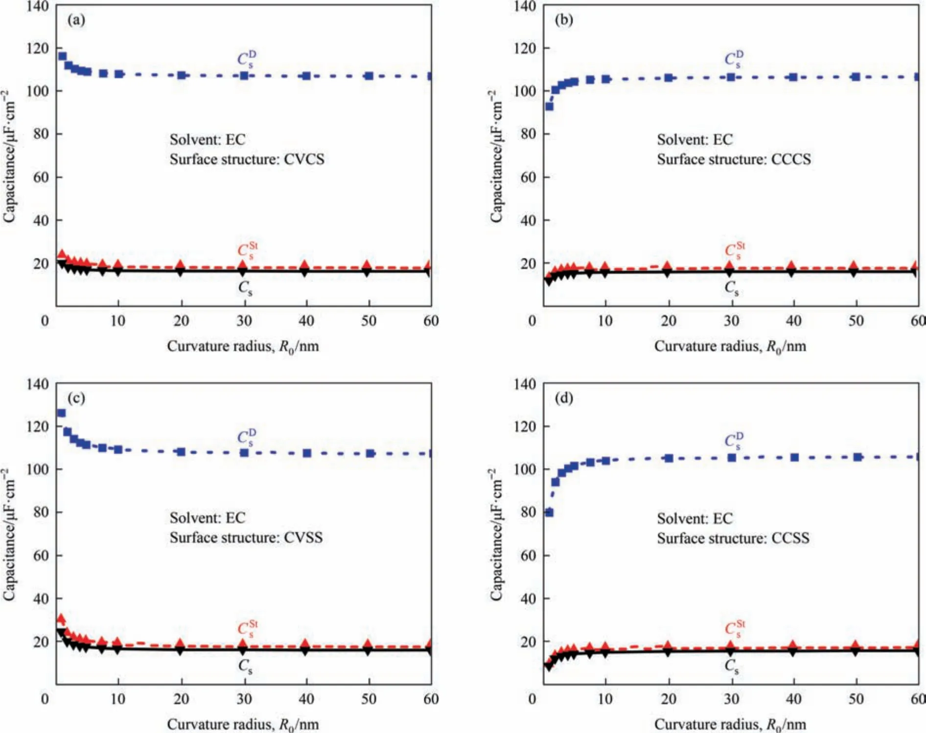
Fig.2.Numerically predicted Stern layer,diffuse layer,and total specific surface capacitances as a function of curvature radius ranging from 1 to 60 nm with electrode immersed in the TEABF4/EC electrolyte for (a) CVCS,(b) CCCS,(c) CVSS,and (d) CCSS structures.
As mentioned in Section 2.1,the convex surface structures(CVSS and CVCS) represent the interfaces of spherical/cylindrical nanoparticles and the electrolyte (outside surface),while the concave surface structures(CCSS and CCCS)represent the interfaces of spherical/cylindrical nanopores and the electrolyte (internal surface).The simulation results in Fig.3 thus indicate that the small particles and pores less than 20 nm can significantly influence the total specific surface capacitanceCsof EDLCs.This conclusion based on the numerically predicted results is well consistent with the consequences from the experimental results [5,16,46-48].
To highlight the effect of meso-macropore surface structure on specific surface capacitance,the parameter ΔCsis expressed as the difference of specific surface capacitance between other surface structures and the FS structure,using theCsof FS structure as a reference value and displayed in Fig.4.As shown in Fig.4,for all electrolytes in this study,the convex surface structures increase the specific capacitance while the concave surface structures decreased the specific capacitance.The spherical surface structures,either the external surface (convex) or the internal surface(concave),affect the specific capacitance more significantly than the cylindrical convex/concave surfaces.Most importantly,the impact of carbon material nanostructure depends strongly on the curvature radius.The smaller the curvature radius is,the larger the absolute ΔCsis.
Therefore,for the purpose of enhancing specific capacitance of EDLCs,small particles but large pores are preferred for electrode material,namely,for nanoparticles,the smaller the better;for nanopores,the larger,the better.However,this requirement is contradictory for the real electrode material in which nanoparticles(with or without pores inside) accumulated together with pores filling the void.The reduction of nanoparticle size usually downsizes the nanopores at the same time,thus the enhancement ofCsby the former could be neutralized by the weakening of theCsby the latter.Therefore,an optimal performance is expected to achieve by a nanostructured carbon material with high specific surface area and well-balanced nanoporosity.
3.2.Effects of organic solvent polarity
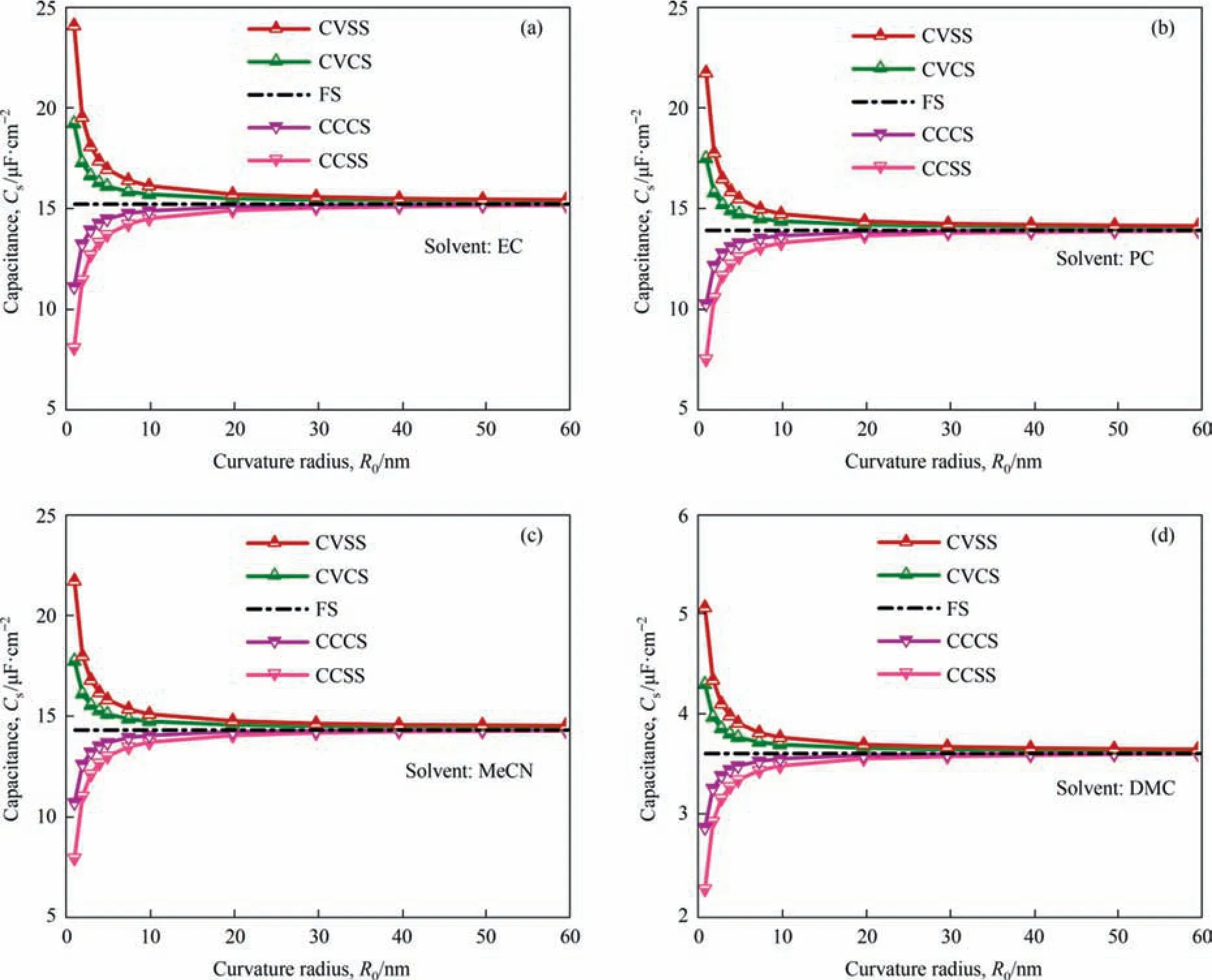
Fig.3.Numerically predicted total specific surface capacitance for CVCS,CCCS,CVSS,and CCSS structures with curvature radius ranging from 1 to 60 nm.And electrode is immersed in four electrolytes: (a) TEABF4/EC,(b) TEABF4/PC,(c) TEABF4/MeCN,and (d) TEABF4/DMC.
Fig.4 also shows that although the ΔCsvariation with curvature radius follows the same trend for all solvents,it does differ for solvents with different polarities.Therefore,in this section,the effect of organic solvent polarity is systematically investigated.Fig.5(a)and(b)show the simulated specific capacitanceCsof EDLCs in electrolytes with different polarities for two surface structures (CVCS and CCCS) at curvature radius of 1,4 and 20 nm,where the electrolyte polarity is represented by the zero-field dielectric permittivity εr(0).In general,the total specific surface capacitance increases with the increasing solvent polarity.Specifically,Csincreases significantly with the increase of the polarity when εr(0)is less than 30,while no significant change is observed when a more polar solvent is used.However,as shown in Fig.5(a),although the εr(0)of solvent PC is 61.4,much higher than that of solvent MeCN as 32.7,theCsof EDLCs with TEABF4/PC as electrolyte is 17.38 μF·cm-2atR0=1 nm,slightly lower than theCsof EDLCs (17.6 μF·cm-2,R0=1 nm) with TEABF4/MeCN as electrolyte.A similar trend could be observed for EDLCs with the carbon structure of CCCS,as shown in Fig.5(b).The confusing phenomenon that MeCN-based electrolytes show higher capacitance than PC-based electrolytes is in agreement with previous experimental studies,classical density functional theory calculations and MD simulations,all of which prove the reliability of the current simulation results [49-51].
Previous theoretical research demonstrated that the molecularscale solvent effects within the Stern layer,containing dipole moment[50],molecule orientation[51],molecule-electrode interaction and molecule-ion interaction [52],play important roles in capacitance performance.To understand what causes the above seemingly abnormal phenomenon about capacitance change with solvent polarity at the meso-macro scale,we show the counterion distribution and dielectric permittivity within the different pore structures immersed in the different electrolytes in Figs.S4-S5.The variation tendencies of capacitance shown in Fig.5(a),(b)agrees well with that of dielectric permittivity near the interface of the Stern layer and the Diffuse layer shown in Fig.S5(b,d),it is important to analyze the dielectric permittivity of electrolytes within the Stern layer.Therefore,we further show the dielectric permittivity of the Stern layer for solvent PC and MeCN on the occasion of 4 surface structures at the curvature radius of 1,4,and 20 nm.Only results for CVCS and CCCS are displayed for simplicity in Fig.5(c) and (d),respectively.It can be seen that the relative dielectric permittivity within Stern layer for TEABF4/MeCN electrolyte is slightly higher than that for TEABF4/PC electrolyte,which justifies theCswith TEABF4/MeCN electrolyte is slightly higher than that with TEABF4/PC electrolyte.
Thus our simulation results indicate that the solvent effects within the Stern layer should be further emphasized,which has also been validated by previous MD studies at the molecular scale[51,52].More specifically,at the initial stage of the charging process,the solvent molecules are gradually aligned against the charged wall as the electric field intensity increases[38,50].When all the solvent molecules are aligned against the charged wall,the dipole moment or molecule orientation will not change much even in a higher electric field[53,54].Danielset al.[35]investigated the variation of dielectric constant with potential in a high electric field and found a saturation phenomenon at the atomic scale.They did have measured a higher dielectric constant for MeCN than that for PC in a relatively high electric field,which means that the saturated dielectric permittivity of MeCN was higher than that of PC in a high electric field.Therefore,for organic solvents,it is the saturated dielectric permittivity instead of the zero-field dielectric permittivity that determines the total capacitance performance.
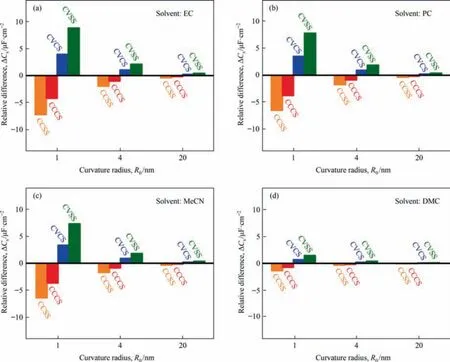
Fig.4.The specific surface capacitance difference between the different surface structures and the FS structure when the curvature radius is 1,4,and 20 nm.
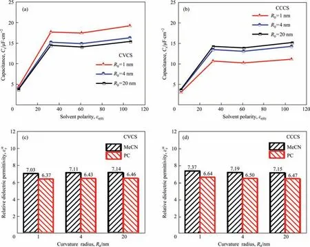
Fig.5.Variation of numerically predicted total specific surface capacitance with electrolyte polarity when the curvature radius is 1,4,and 20 nm for(a)CVCS and(b)CCCS;The relative dielectric permittivity within the Stern layer for MeCN and PC when the curvature radius is 1,4,and 20 nm for (c) CVCS and (d) CCCS.
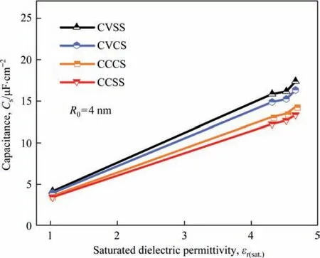
Fig.6.Correlation of numerically predicted total specific surface capacitance with the saturated dielectric permittivity for CVCS,CCCS,CVSS,and CCSS structures when the curvature radius is 4 nm.
Here,the saturated dielectric permittivity εr(sat.)is defined as the relative dielectric permittivity εr(E) while the electrical fieldEis 4 V·nm-1.Then,we correlate again the simulatedCsof EDLCs with saturated dielectric permittivity εr(sat.)at a surface curvature radius of 4 nm as shown in Fig.6.It is obvious that regularly theCsincreases with the saturated dielectric permittivity.Therefore,for organic solvents,the high saturated dielectric permittivity is preferred to enhance the specific capacitance of EDLCs,and the saturated dielectric permittivity should be required as a noteworthy parameter for developing and designing new organic electrolytes.
3.3.Electrode meso-macropore structure vs electrolyte property
Section 3.1 and 3.2 have indicated that both meso-macropore surface structures of different curvature radius and the electrolyte dielectric permittivity can influence the totalCsof EDLCs considerably,but which one is the most critical factor to optimize the capacitance of EDLCs? We intend to answer this question in this section.
In order to compare the contribution from electrode mesomacropore structure with that from electrolyte polarity to the performance of EDLCs,change of both total specific capacitanceCsand the relative electric permittivity within Stern layer with surface curvature radius for all four surface structures (CVCS,CCCS,CVSS and CCSS) and four different electrolytes (TEABF4/EC,TEABF4/PC,TEABF4/MeCN and TEABF4/DMC) have been calculated.Only the results for the TEABF4/EC electrolyte are exhibited in Fig.7 as a representative,the others are presented in the Supplementary Material.
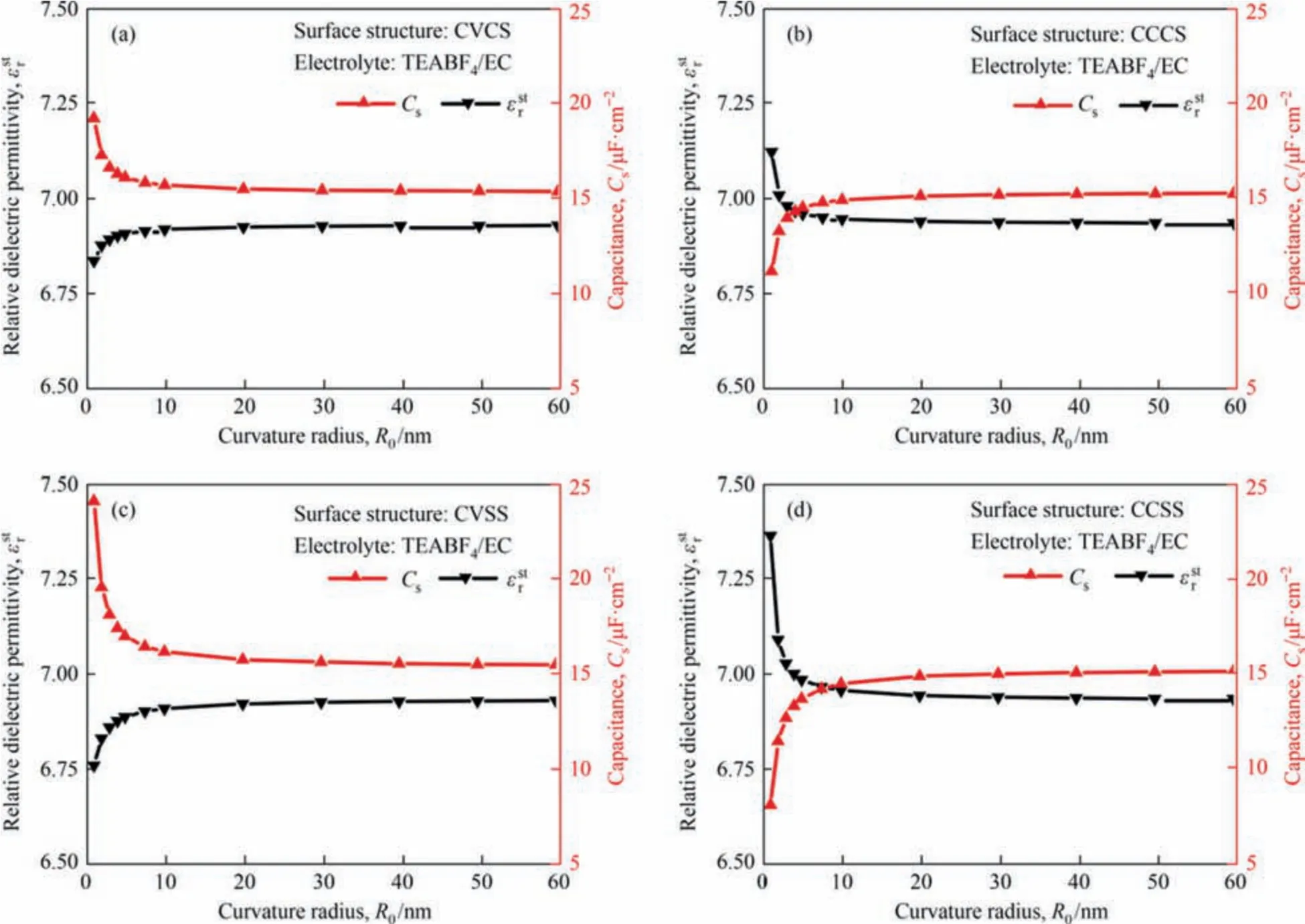
Fig.7.Numerically predicted relative dielectric permittivity within the Stern layer and total specific surface capacitances as a function of curvature radius ranging from 1 to 60 nm with electrodes immersed in the TEABF4/EC electrolyte for CVCS,CCCS,CVSS and CCSS structures.
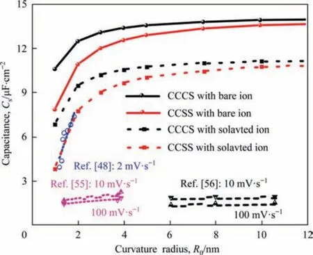
Fig.8.Numerically predicted and experimentally measured specific surface capacitance as a function of curvature radius ranging from 1 to 12 nm.And numerical results are obtained with two surface structures: CCCS and CCSS.
As seen from Fig.7(a) and (c),for convex surface structures(CVCS and CVSS) immersed in the TEABF4/EC electrolyte,the total specific surface capacitance decreases with the increase of curvature radius,but the relative dielectric permittivity of electrolyte within Stern layer increases with the increase of curvature radius.On the contrary,as seen in Fig.7(b) and (d),for concave surface structures(CCCS and CCSS)immersed in the TEABF4/EC electrolyte,the total specific capacitance increases with the increase of curvature radius while the relative dielectric permittivity of electrolyte within Stern layer decreases with the increase of curvature radius.The opposite trends in the change of total specific capacitance and the relative dielectric permittivity with curvature are also observed for the other three electrolytes as presented in Figs.S6-S8.
As known from Section 3.2,Csshould increase with the increase of the saturated dielectric permittivity of electrolyte within the Stern layer if the other parameters are constant.But it can be seen from Fig.7 that the dielectric permittivity either increases for convex surface structures or decreases for concave surface structures with the curvature radius for the TEABF4/EC electrolyte,theCsfollows opposite trends,which means that the contribution from the electrolyte solvents can be neglected compared to the mesomacropore structure of curvature radius ranging from 1 to 20 nm.
Variation of total specific capacitance in Fig.7 mainly shows the effects of the meso-macropore surface structure on the performance of the EDLCs.For these convex surface structures,as the curvature radius decreases,the electric field becomes higher and then more counterions are adsorbed in the charged wall,hence a larger specific surface capacitance.However,for these concave surface structures,as the curvature radius decreases,the electric field becomes lower and then counterions are desorbed from the charged wall,hence a lower specific surface capacitance.Therefore,the electrode meso-macropore and its curvature radius,rather than the electrolyte,is the main factor to impact the capacity of the charge storage of the EDLCs and should be of more concern when aiming at enhancing the total specific capacitance.This could explain why so much research has been working on developing more and more innovative nanostructures of carbon material for EDLCs.
3.4.A comparison between the simulation and the experiment results
Our simulation on the effect of the meso-macropore structure of carbon electrodes on the capacitance of EDLCs suggests that balancing the nanoparticle size and the nanopore size could enhance the electrochemical performance.This conclusion is drawn based on the mathematical modelling of the typical surface structure instead of the real bulk electrode.Hence the applicability of these conclusions needs to be verified.The capacitance of either the bulk electrodes or the typical surface structure of carbon material is determined by the interface of electrode and electrolyte,i.e.,the electrochemically available electrode surface area in the considered electrolytic medium.
To validate our conclusion,the numerically predicted results are compared with the experimental results reported by Vix-Guterlet al.[48,55,56].They synthesized ordered mesoporous carbon materials possessing pore radius distribution from 1 to 12 nm and measured capacitances from cyclic voltammetry at different scan rates in the TEABF4/MeCN electrolyte.We here used the simulation method established in this work,and numerically predictedCsof the two concave surface structures (represent internal surfaces of spherical and cylindrical nanopores) with curvature radius ranging from 1 to 12 nm in the TEABF4/MeCN electrolyte.Then a comparison was made between our predictedCsand the experimentally measuredCsfor the electrode made of ordered porous carbon material in Ref.[48,55,56],as displayed in Fig.8.
The variation tendencies ofCswith the pore size for experimental results and that with the curvature radius are very similar,but the numerically predicted values from either the CCCS or the CCSS still are larger than the experimentally measured ones.This is because in the simulation,non-solvated ions with smaller diameters are assumed for the capacitance calculation while in the real electrode,ions are always surrounded by solvent molecules,and the larger solvated ions lead to the lower capacitance of EDLCs.Meanwhile,the predicted values are the equilibrium capacitances when the scanning rate is close to zero,whereas experimental capacitances are usually measured at a rather high voltage scanning rate and the capacitance decreases with the increase of scan rate [36].Moreover,our predicted results from the modified steady-state continuum model are of the same order magnitude with the experimentally measured results,which is more accurate than the results of Wanget al.[32].Theirs are larger by several orders of magnitude than the experimental results.This means that although the simulation results in this work could not fully represent the real electrode,the acquired regularity on the dependence ofCson the meso-macropore structure of electrode material and solvent polarity is applicable for guiding the optimization of EDLCs.
As known to all,nanoparticles and nanopores play essential roles in ions adsorption,the balance of nanoparticle size and nanopore size should be optimized to attain the most surface for ion adsorption and thus maximize the capacitance of EDLCs.Unfortunately,it sure is quite difficult to manipulate precisely the nanoparticle size and nanopore size simultaneously and quantitatively investigate their impacts on the capacitance of EDLCs by experiments.However,if we combine the specific surface capacitanceCsand specific surface areaSV,the volumetric capacitance of bulk electrode,expressed asCV=∫CsdSV,could be further predicted based on the mathematical models of typical nanostructure surfaces coupled with the three-dimensional porosity models.Thus,the mathematical simulation would allow to precisely optimize the nanostructure details and provide more fundamentals for the rational design of the electrode material.These strategies are now undergoing,which would be addressed in our future work.
4.Conclusions
In this study,we have quantitatively investigated the simultaneous effects of electrode meso-macropore structure and solvent polarity on the specific surface capacitance of EDLCs,using a modified steady-state continuum model for electric double layer.Five typical surface structures of meso-macropore in four polar organic solvents are simulated mathematically.The results indicate that the total specific surface capacitance is mainly dominated by the capacitance of the Stern layer.For convex surface structures(CVSS and CVCS),the total specific surface capacitance significantly decreases with the increase of curvature radius ranging from 1 to 20 nm.Inversely,for concave surface structures (CCSS and CCCS),the total specific surface capacitance significantly increases with the increase of curvature radius ranging from 1 to 20 nm.Therefore,the small particles and small pores with curvature radius less than 20 nm can significantly influence the total specific surface capacitance of EDLCs,and optimal performance is expected to achieve with a nanostructured carbon material of high specific surface area and well-balanced nanoporosity.
There exists a saturation phenomenon for the dielectric permittivity of organic electrolyte solvents under a high potential field inside the EDLCs.Our simulation reveals that the saturated dielectric permittivity rather than the zero-field dielectric permittivity determines the capacitance performance of EDLCs.
Moreover,the electrode meso-macropore structure is the main factor to impact the capacitance of EDLCs compared with electrolyte solvent,in other words,tuning the electrode mesomacropore structure should be of more concern when aiming at enhancing the capacitance.These results will guide the rational design of electrode material nanostructure and the selection of solvent to achieve enhanced energy density of EDLCs and even other battery systems.
Declaration of Competing Interest
The authors declare that they have no known competing financial interests or personal relationships that could have appeared to influence the work reported in this paper.
Acknowledgements
This work was financially supported by the National Basic Research Program of China (2014CB239702),the National Natural Science Foundation of China (21676082and 22008067),and the China Postdoctoral Science Foundation (2020M681202 and 2021T140204).
Supplementary Material
Supplementary data to this article can be found online at https://doi.org/10.1016/j.cjche.2022.06.011.
Nomenclature
Asarea of electrode surface,cm2
aion diameter,nm
Cstotal specific surface capacitance,μF·cm-2
specific surface capacitance of diffuse layer,μF·cm-2
specific surface capacitance of Stern lay er,μF·cm-2
cmmaximum ion concentration,mol·L-1
c∞bulk molar concentration of electrolyte,mol·L-1
Enorm of the local electrical field vector,V·m-1
E electric field vector
e elementary charge (=1.602×10⁻¹⁹C)
HStern layer thickness,nm
kBBoltzmann constant (=1.3806×10⁻²³J·K-1)
Ldiffuse layer thickness,nm
NAAvogadro constant (=6.022×10²³mol-1)
nthe index of refraction of electrolyte
n the local outward normal unit vector at electrode surface
Qtotal charge stored at electrode surface,C
R0curvature radius,nm
rlocation in one-dimensional space,nm
SVspecific surface area,cm-1
Tabsolute temperature,K
v packing parameter
zion valence
β fitting parameter of Booth model,nm·V-1
εrrelative dielectric permittivity of electrolyte
εr(0)zero-field dielectric permittivity
εr(sat.)saturated dielectric permittivity
ε0free-space dielectric permittivity
ψ electric potential,V
ψDpotential at the interface of Stern layer and diffuse layer,V
ψspotential of electrode,V
ΔψDpotential differences of Stern layer/diffuse layer interface and bulk electrolyte,V
Δψspotential differences of electrode and bulk electrolyte,V
 Chinese Journal of Chemical Engineering2022年10期
- Chinese Journal of Chemical Engineering的其它文章
- Enhance hydrates formation with stainless steel fiber for high capacity methane storage
- Refrigeration system synthesis based on de-redundant model by particle swarm optimization algorithm
- Adaptive multiscale convolutional neural network model for chemical process fault diagnosis
- Injectable self-healing nanocellulose hydrogels crosslinked by aluminum: Cellulose nanocrystals vs.cellulose nanofibrils
- Establishment of nucleation and growth model of silica nanostructured particles and comparison with experimental data
- Molecular dynamics simulations of ovalbumin adsorption at squalene/water interface
