Synthesis of vertical graphene nanowalls by cracking n-dodecane using RF inductivelycoupled plasma-enhanced chemical vapor deposition
Jiageng ZHENG (鄭佳庚), Qinhuai TAN (譚欽懷), Hang CHEN (陳航),Angjian WU (吳昂鍵),3, Xiaodong LI (李曉東),3, Jianhua YAN (嚴(yán)建華),Jiaxu DAI (戴佳栩) and Jiao ZHOU (周嬌)
1 State Key Laboratory of Clean Energy Utilization, Institute for Thermal Power Engineering, Zhejiang University, Hangzhou 310027, People’s Republic of China
2 China United Engineering Corporation Limited, Hangzhou 310000, People’s Republic of China
Abstract A facile and controllable one-step method to treat liquid hydrocarbons and synthesize vertical graphene nanowalls has been developed by using the technique of inductively-coupled plasmaenhanced chemical vapor deposition for plasma cracking of n-dodecane.Herein,the morphology and microstructure of solid carbon material and graphene nanowalls are characterized in terms of different operating conditions, i.e. input power, H2/Ar ratio, injection rate and reaction temperature. The results reveal that the optimal operating conditions were 500 W, 5:10,30 μl min?1 and 800°C for the input power,H2/Ar ratio,injection rate and reaction temperature,respectively. In addition, the degree of graphitization and the gaseous product are analyzed by Raman spectroscopy and gas chromatography detection. It can be calculated from the Raman spectrum that the relative intensity of ID/IG is approximately 1.55,and I2D/IG is approximately 0.48, indicating that the graphene prepared from n-dodecane has a rich defect structure and a high degree of graphitization. By calculating the mass loading and detecting the outlet gas, we find that the cracking rate of n-dodecane is only 6%-7%and that the gaseous products below C2 mainly include CH4,C2H2,C2H4,C2H6 and H2.Among them,the proportion of hydrogen in the outlet gas of n-dodecane cracking ranges from 1.3%-15.1% under different hydrogen flows.Based on our research, we propose a brand new perspective for both liquid hydrocarbon treatment and other value-added product syntheses.
Keywords: ICPECVD, n-dodecane cracking, vertical graphene nanowalls
1. Introduction
N-dodecane(C12H26),a liquid hydrocarbon,is described as a special liquid waste with a high carbon content after it is effectively utilized. Nevertheless, in the absence of thorough disposal, n-dodecane may cause serious environmental pollution due to its high diffusivity,wide pollution range and large secondary toxicity. For this reason, developing an environmentally friendly way to dispose of n-dodecane has sparked great interest for society.
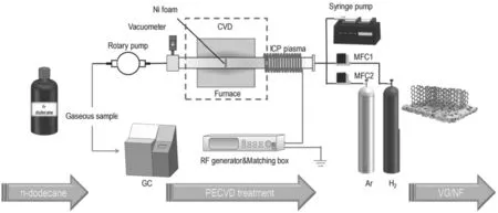
Figure 1.Graphical abstract of the system to treat n-dodecane and synthesize VGs.
Recent investigations for the disposal of liquid hydrocarbon waste mainly consist of physical methods and chemical methods. For instance, Osmanlioglu et al introduced a way of absorbing radioactive liquid hydrocarbon waste by using natural zeolite, and a decontamination factor of 430 was achieved under optimum conditions [1]. In addition,the chemical method put more emphasis on the reforming process of the liquid hydrocarbons to obtain hydrogen,micromolecular gaseous hydrocarbons or carbon materials.Gould et al systematically studied autothermal reforming of n-dodecane with different ratios of O/C and H2O/C over nickel-based catalysts and obtained various proportions of CO, CO2and H2syngas [2]. However, the current technologies for the disposal of liquid hydrocarbon waste mentioned above have many disadvantages such as high energy consumption, incomplete treatment, secondary pollution and the need for sophisticated facilities.
With respect to the issues above, considerable effort has been devoted to improve the performance of the reforming process by reducing the energy consumption of the plasma process. Therefore, different types of non-thermal plasma technology,such as gliding arc plasma[3,4],glow discharge[5-7], microwave plasma [8, 9], RF plasma [10, 11], dielectric barrier discharge [12, 13], corona discharge [14, 15],plasma jet [16, 17] and spark [18, 19] offer attractive alternatives to the conventional catalytic process for activating low-value and inert molecules into clean fuels and highervalue chemicals at atmospheric pressure and low temperatures[20-22]. In the meantime, a lot of competitive plasma-based methods for the reforming of n-dodecane at ambient conditions have been investigated. Mochtar et al investigated the effect of gas flow rate on the gas production rate from n-dodecane using steam reforming in-liquid plasma and the maximum hydrogen generation efficiency was obtained up to 59% [23]. Ma et al investigated the plasma reforming of n-dodecane for the co-generation of COx-free hydrogen and C2hydrocarbons in a gliding arc discharge reactor and achieved the highest selectivities of H2(76.7%), C2H2(41.4%) and C2H4(12.0%) with n-dodecane conversion of 68.1% [24]. Among various plasma sources, however,inductively-coupled plasma (ICP) reveals an impressive function in both graphene fabrication and liquid hydrocarbon treatment due to its own high plasma density and the generation of abundant active species (ions, excited molecules,radicals and photons) [25].
Herein, we propose a facile and controllable one-step method to treat liquid hydrocarbons and synthesize vertical graphene nanowalls (VGs) by using inductively-coupled plasma-enhanced chemical vapor deposition (ICPECVD).Our experimental system differs from other treatment processes in that it provides a new way to treat n-dodecane,which is catalyst-free and under relatively mild conditions.Moreover, this approach can obtain high-value graphene,which could be widely used in various fields.Compared with our previous study, we first propose the strategy of using the ICPECVD technique to treat liquid hydrocarbons. In the present paper, the morphological, spectral and electrical parameters of graphene growth are investigated. First, the influence of different operating conditions (applied power,gas proportion, injection rate and reaction temperature) on electrical parameters is analyzed to determine the optimal operating conditions for VG growth.In addition,the effect of operating conditions on the properties of the solid products is investigated by scanning electron microscopy (SEM) and Raman spectroscopy. The results demonstrate the morphology of graphene under different conditions along with the degree of graphitization of graphene. Gaseous products have been thoroughly investigated to explore the generation mechanism of all free radicals.Based on these investigations,we expect to advance our understanding of graphene fabrication. Furthermore, this understanding may provide a brand new way to develop a feasible and controllable synthesis approach for diverse applications.
2. Experiment and methods
In our experiment,the main plasma reactor is a combined ICP generator and CVD reactor.A schematic diagram is shown in figure 1. A cylindrical configuration comprises a quartz tube(48 mm in diameter and 1000 mm in length)and is fixed on a furnace.One end of the quartz tube is surrounded by a copper coil to cool the quartz tube to prevent tube overheating.
For the experimental setup,plasma is stimulated by a RF power generator (Kmate, HERO-500 W, 13.56 MHz) and regulated by a matching box.Ni foam is used as the substrate for graphene growth in this experiment and was washed thoroughly with ethanol and deionized water before use. The carrier gas (Ar and H2) is adjusted by a mass flow controller(Seven Star D07). A rotary pump (KYKY, RVP-2) was applied to maintain a low-pressure atmosphere(0.1-0.5 torr),which is vital to ICP generation.In addition,n-dodecane was injected into the quartz tube inlet by a syringe pump(LONGER, LSP01-1A).
At the beginning of the process,the Ni foam is anchored in a quartz boat, and then placed in the quartz tube. Air is evacuated by the rotary pump after the quartz tube is completely sealed. The heating device starts to run according to the setting program along with the aeration of the carrier gas.The plasma is generated when the temperature reaches the setting value.In the meantime,the n-dodecane is injected into the quartz tube inlet by the syringe pump and the gaseous products are collected at the exhaust by a gas bag. Ten minutes is most appropriate for the whole treatment time according to our previous study.
In the detection section,gaseous products are tested by a gas chromatograph (GC9790A, Fuli Analytical Instrument Co., Ltd). Hydrogen is measured by a thermal conductivity detector and the gaseous products below C2(CH4, C2H2,C2H4and C2H6) can be detected by a flame ionization detector.
The prepared graphene nanowall structure and morphology are further characterized via SEM (Ultral 55) and Raman spectroscopy (Labor Raman Series, HR-800, 514 nm laser).
3. Result and discussions
3.1. Characterization of thermal and electrical properties in n-dodecane cracking
3.1.1. Effects of the applied power input. As a source of energy in this process, plasma could provide a huge number of high-energy electrons to collide with gas molecules. The probability that n-dodecane obtains energy by collision and cracks into small molecules or active groups will increase when the applied power input of the plasma increases,which means high electron density has been achieved. The active groups can also provide a rich raw material for the growth of the carbon material on the catalyst substrate. In addition, the higher the applied input power is, the higher the energy conversion efficiency, and both high-density electrons and active groups are helpful in enhancing the degree of graphitization and the growth area of the carbon material.For this reason, the applied input power has a significant influence on n-dodecane cracking and carbon material growth on Ni foam.
Figure 2 illustrates the morphology of the synthesized graphene nanowalls with increasing applied input power. As shown in figure 2(a), no visible vertical graphene nanowalls are observed with the 300 W applied input power. Instead, a flattened ‘totem-like’ dot-line distribution can be seen. The lines are connected to each other and terminate at some dot positions. On the macro level,the dot-line structure is evenly distributed on the surface of the Ni substrate. It is confirmed that a large amount of carbon nanowires formed on the Ni substrate by the deposition of the carbon atoms. The dots observed may be the nucleation points for the growth of the graphene nanowalls. The above observations indicate that there is not enough raw material available for the selfrecombination of carbon atoms in these conditions, and most n-dodecane molecules are not excited into active groups. In addition, because the system temperature is maintained at 800°C, a large amount of long hydrocarbon chains will not accumulate on the surface of the Ni foam.
When the applied input power is increased to 400 W, it can be observed that the carbon structure on the surface of the Ni foam begins to change. The original dot-line structure begins to grow in the vertical direction and has a morphology similar to graphene, indicating that the active groups exist in the reaction region. In the partially enlarged view of figure 2(c), it can be observed that the length of the carbon material with this structure is approximately 50-100 nm, and the thickness is wider than that with 300 W.
When the applied input power reaches the maximum value of 500 W in the experimental system, as shown in figures 2(e) and (f), the structure of the graphene becomes relatively regular in both length and width. Its lateral dimension increases to between 500 nm and 1 μm, while the thickness of the graphene nanowalls is relatively thin.Compared with the dense distribution at 400 W, more cavity structures are formed between the graphene nanowall layers.It is believed that graphene nanowalls with relatively high thickness have superior electrical properties.
3.1.2. Effect of hydrogen/argon ratio. Similarly, the proportion of the reaction atmosphere is also critical for the growth of graphene nanowalls.Ar is a shielding gas that also collides with electrons in the plasma region,and the Ar atoms in the excited state will continue to collide with other particles to absorb energy, while also transmitting energy. H2will directly affect the growth and morphology of graphene in two ways: one, H2collides with the n-dodecane molecule in the plasma region and then produces CnHx(especially CHx),which is an important raw material for the formation of graphene nanowalls;the other effect is that the hybrid carbon,thicker carbon layers and amorphous carbon can be etched by the H radicals coming from H2cracking. Therefore, H2has a certain effect on the defect structure modification of the graphene nanowall layers to obtain highly graphitized graphene nanowalls.
Figures 3(a)-(c)show the carbon material structure when the flow rate of H2is 5 sccm and the flow rates of Ar are 5,10 and 20 sccm, respectively. As the flow rate of Ar increases,the carbon material on the surface of the Ni foam gradually changes from some nucleation points with a sparse distribution of carbon to many graphene nanowall layers of a certain scale, and finally to dense agglomerations of carbon particles on the surface. First, the relationship between absorption energy and transfer energy of Ar radicals is balanced in the process of n-dodecane cracking. When the Ar flow rate is 5 sccm,a large number of nucleation sites are distributed on the Ni substrate, but no nanowall structure appears. The above observation indicates that the component density to form graphene is not enough with a 5 sccm Ar flow. However, Ar with a low flow rate corresponds to a higher average input energy of n-dodecane molecules.This result indicates that Ar has an important effect on energy transfer and cracking promotion during the n-dodecane cracking process. This effect may occur because the high-energy electrons are not sufficient to directly motivate the n-dodecane,which requires Ar and H2as a medium.When the flow rate of Ar increases to 20 sccm,it is observed that the graphene nanowall structure is polycondensed into nanocarbon particles, the scale of which is much smaller than graphene. On the one hand, it can be considered that the energy absorption effect of Ar at this time is stronger than the energy transfer effect, the stronger absorption effect leads to the incomplete decomposition of n-dodecane and a large number of active groups of C3-C6,which are formed by the attraction of unsaturated bonds at the nucleation point. On the other hand, the reduction of energy causes the increase of surface stress on the carbon material,presenting a spherical structure. There are not enough H radicals to etch it at this time,so the carbon material stacks as the particle layers shown in figure 3(c).
Figures 3(b) and (d) reveal graphene nanowall structure at H2flow rates of 5 and 10 sccm.Among them,the position of the red circle in figure 3(b) can be observed as a hybrid carbon structure, which is due to the different ways of bonding available to the carbon atoms in the graphene. To obtain graphene with a higher degree of graphitization,it can be etched by H2, and by comparing the above two results,increasing the H2flow rate can effectively reduce the complex and dense stacked carbon structure in graphene nanowalls and obtain a more crystalline carbon structure. Therefore, we can conclude that the energy distribution and species of reactive groups in the plasma region can be regulated to an optimum condition by controlling the proper flow rate and ratio of hydrogen/argon, which plays a crucial role in the formation of graphene nanowall structures.
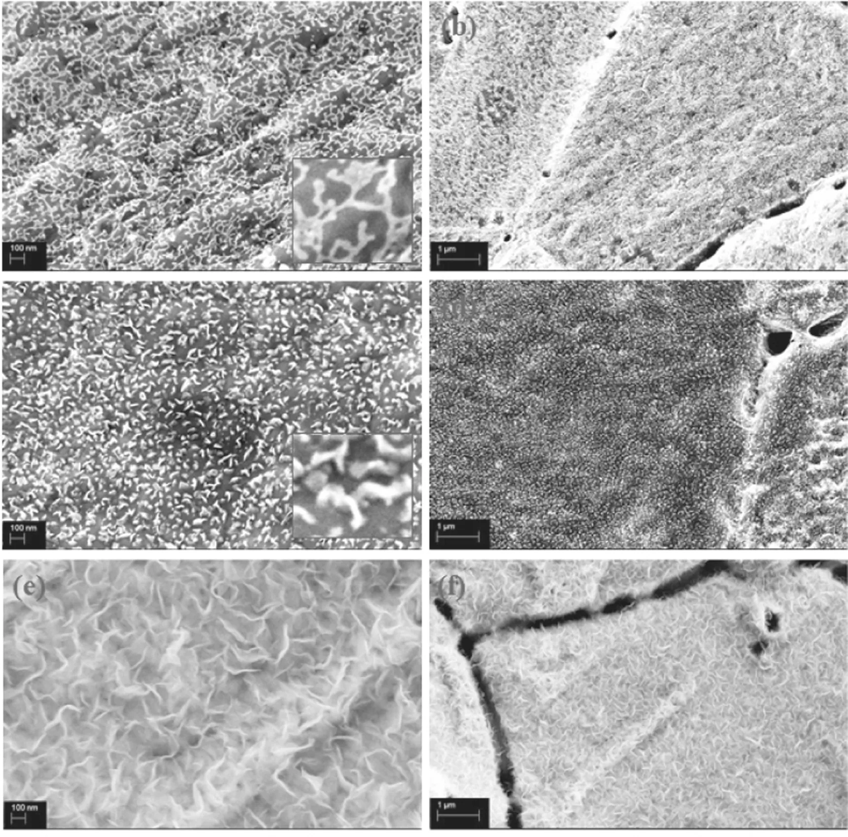
Figure 2.SEM images of carbon materials prepared at different applied powers for 10 min:(a),(b)300 W;(c),(d)400 W;(e),(f)500 W(H2/Ar = 5:10, 30 μl min?1, 800°C).
3.1.3. Effect of the injection rate of n-dodecane. Under the synergistic effect of ICP and high-temperature heating,n-dodecane molecules will be cleaved into free radicals such as CH,H,CH2,CH3and C2.The C2is currently considered as the most important raw material in the growth process of graphene nanowalls due to its olefinic structure. However,compared with the cracking of methane, more C3-n(n > 3)active substances exist during the cracking of n-dodecane.Therefore,the degree of cracking of n-dodecane may affect the type of available components and distribution of active particles for the entire reaction zone.
Figure 4 shows the carbon materials obtained at two different injection rates: 30 μl min?1(a) and 50 μl min?1(b).When the injection rate of n-dodecane is increased, the surface of the Ni foam is unevenly distributed with granular agglomerate structure rather than graphene nanowalls. It can be confirmed that the increase of the injection rate means the increase of the proportion of carbon source components. The total number of gas molecules in the area increases when n-dodecane is uniformly propelled into the plasma reaction zone by a syringe pump, because the n-dodecane will be directly vaporized under the conditions of high-energy particle collision and low pressure. Similar to the increase of Ar flow, the n-dodecane molecule cannot obtain sufficient energy density for effective cracking at this time,in which the proportion of small molecular active groups will decrease,while the macromolecular active groups will increase and adhere to the pores of the Ni foam. Therefore, the active group materials and mechanism for carbon material growth have changed and led to the graphene nanowall structure not being produced on the surface of the Ni foam.
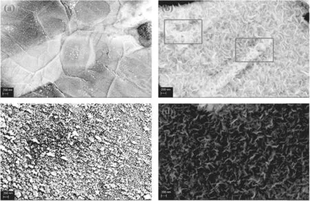
Figure 3.SEM images of carbon material prepared in 10 min at different H2/Ar ratios: (a) 5:5; (b) 5:10; (c) 5:20; (d) 10:10 (500 W,30 μl min?1, 800°C).

Figure 4.SEM images of carbon material prepared at different n-dodecane injection rates for 10 min: (a) 30 μl min?1 and (b) 50 μl min?1(500 W, H2/Ar = 5:10, 800°C).
3.1.4.Effect of reaction temperature. The reaction temperature is an important influencing factor in this experimental system,especially the synergistic effect of high temperature,which can effectively reduce the power required by the plasma and reduce the adhesion of macromolecular particles.In previous research,carbon materials such as activated carbon, carbon nanotubes[26-28] and fullerenes [29] were generally prepared by CVD.In the conventional method of CVD, the reaction temperature needs to reach above 1000°C [30] and the operation time needs more than half an hour. Furthermore, we also need to provide more than 1000 W to the plasma source during the process of preparing graphene by plasma cracking. A high electron temperature also causes high macro temperature. The reaction temperatures mentioned above all pose challenges and requirements for the reaction equipment and energy input. Hence, searching for an effective way to lower the reaction temperature or seeking the most appropriate reaction temperature is also one target of this experiment.
Currently, the method based on PECVD can provide an atmosphere with lower macroscopic temperature,which is one of the mainstream methods for preparing carbon materials[31-35].However,the reaction temperature in this experiment has an effect on both the gasification process of n-dodecane and the stabilization of excited-state particles. Therefore, the reaction temperature directly affects the structure and morphology of the carbon materials.
Figure 5 shows the structure of the carbon material at reaction temperatures of 600°C, 700°C, 800°C and 900°C.When the heating temperature of the reaction is 600°C,it can be observed that the surface of the Ni foam is covered by a dense macromolecule, and it can be inferred from the SEM results that the conductivity is poor. Therefore, the hydrocarbon layer may be because the n-dodecane molecule does not obtain enough energy during the gasification process,and a large amount of the liquid hydrocarbon molecules are deposited on the surface of the Ni foam. When the reaction temperature is increased to 700°C, a large number of nucleation sites are formed on the surface of the Ni foam.This outcome indicates that active groups such as C2have been produced at this time. Meanwhile, the energy obtained by the n-dodecane molecule ensures that it will not adhere to the Ni substrate. When the reaction temperature reaches 800°C,the abundant active groups such as C2and CnHxgrow in the vertical direction at the nucleation point, and a graphene nanowall structure with a lateral dimension of 500-800 nm is prepared. This nanowall structure has a dense maze-like distribution on the plane and interlocks to form a void space. When the reaction temperature increases to 900°C, the formation of clustered graphene nanostructures can be observed. Compared with graphene nanowalls, the lateral dimension is only approximately 200 nm, which is only 1/4-1/3 of the layer structure. Furthermore, the cluster structure is denser and the pore structure is greatly reduced.At the same time, a similar layer structure with a scale of several tens of nanometers can be found from the partial enlargement of the surface of the flower cluster structure,possibly because under the condition of high temperature,the active groups of graphene are agglomerated when growing along a vertical orientation.A cluster of flower-like structures is formed under the action of surface stress,and the size of the surface layer structure is also limited due to the compression of the space.
Compared with the ICP cracking process of methane in the previous work [36], where only a temperature range of 700°C-800°C modified and densified the graphene nanowalls, the structure of the carbon material prepared by n-dodecane is more sensitive to the changes of the reaction temperature.
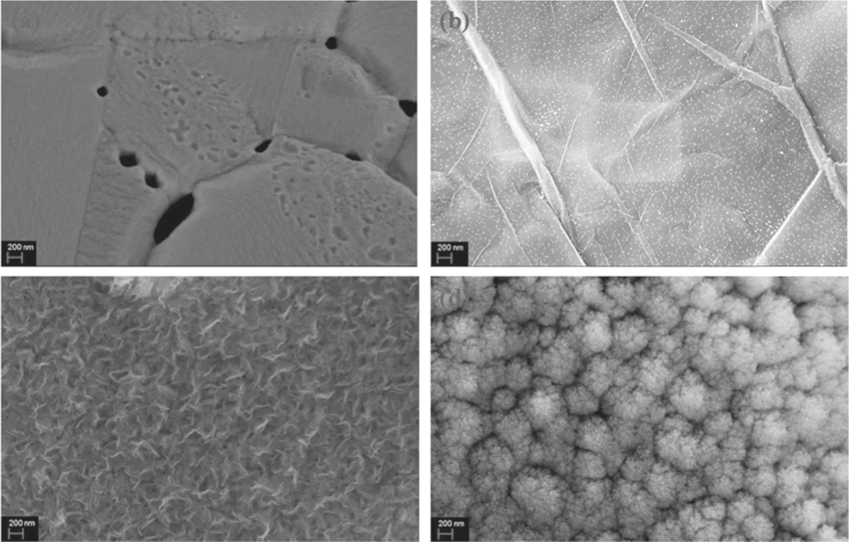
Figure 5.SEM images of carbon material prepared at different reaction temperatures for 10 min: (a)600°C, (b) 700°C,(c)800°C and (d)900°C (500 W, 30 μl min?1, H2/Ar = 5:10).
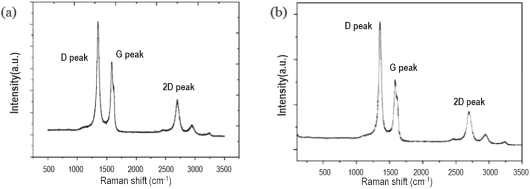
Figure 6.Raman spectrum of graphene prepared by cleaving of n-dodecane (a) and methane (b) ((a) Operating conditions: 500 W, H2/Ar = 5:10, 30 μl min?1, 800°C. (b) Operating conditions: 500 W, H2/Ar = 5:10, 10 sccm, 800°C).
3.2. Graphene structure analysis
Considering the excellent electrical properties of graphene,we now analyze the conductivity of the prepared graphene.The electron transport ability of the graphene nanowalls is related to the degree of graphitization of the structure,because the closer the structure is to the theoretical hexagonal crystal structure of graphene, the more favorable the sp2hybrid orbital is to the movement of electrons.
Figure 6 shows the corresponding graphene structure prepared under the explored optimum conditions of n-dodecane.The crystal structure of graphene is reached by analyzing the D peak (~1354 cm?1), G peak (~1586 cm?1), 2D peak(~2702 cm?1) and D + G peak (~2938 cm?1) in the Raman spectrum.
Among them, the D peak reflects the defect structure of the hexagonal crystal contained in the graphene, and the G peak corresponds to the sp2hybrid structure in the graphene,and ID, IG, I2Dare the intensities of the D peak, G peak and 2D peak, respectively. The intensity of the G peak in figure 6(a)is slightly higher than that in figure 6(b),indicating that the prepared graphene using n-dodecane as a carbon source contains a relatively high proportion of the sp2structure. At the same time, the relative intensity ID/IGof the D peak and G peak in figure 6(a) is approximately 1.55, indicating that there is abundant edge structure or defect structure in the graphene nanowall layers. This outcome is consistent with the dense edge structure observed in the SEM image.
In addition, the 2D peak corresponds to the degree of graphitization of the carbon material, and the D + G peak is the sum of the scattering peaks. In figure 6(a), the highintensity 2D peak means that the graphene nanowall layers have a higher degree of graphitization, and the relative intensity of the 2D peak and G peak at this time I2D/IGis approximately 0.48, which indicates that the graphene nanowall layers are formed by a large number of stacked single layers.
In general, under the same optimized conditions, the graphene nanowalls prepared with n-dodecane and methane have quite similar crystal forms and defect structures. By controlling the appropriate operating parameters, the degree of graphitization of graphene can be effectively improved and the crystal structure can be optimized.
3.3. Analysis of the effect of RF ICP for cracking n-dodecane
Now,a summary of optimized conditions includes an applied input power of 500 W, a hydrogen/argon ratio of 5:10, an injection rate of 30 μl min?1and a reaction temperature of 800°C. And we can analyze and infer the effect and mechanism of the ICP cracking of n-dodecane by analyzing the graphene loading and detection of outlet gas composition.
3.3.1. Graphene loading analysis. To compare the effect of cracking by using ICP with methane and n-dodecane carbon sources,the loading and cracking rate for a similar preparation of graphene with methane at 500 W,H2/Ar = 5:10,20 sccm,800°C and 5 min, is calculated as follows:

where 22.4 l · mol?1is the molar volume of the gas under standard conditions, and 12 g · mol?1is the molar mass of carbon atoms,m1(M1)and m2(M2)are the masses of methane(n-dodecane)before and after reaction,v1is the methane flow rate and v2is the n-dodecane injection rate,while t1and t2are the reaction time.It is worth noting that the graphene obtained at this time has a rich edge structure and a high degree of graphitization. Therefore, it is meaningful to compare the graphene loading from different carbon sources.
As shown in table 1,although we can obtain more carbon material on Ni foam from n-dodecane cracking, it provides a lower graphene ratio compared to methane. In general, the n-dodecane cracking rate is 6%-7%, and the methane cracking rate could reach 13.25%. This outcome indicates that in the plasma region, the proportion of n-dodecane efficiently cleaved into small molecular groups is lower, and more is discharged as gaseous macromolecules. Therefore,to further improve the degradation rate of n-dodecane, the energy density of the plasma reaction region also needs to be correspondingly improved. In addition, if the presence of carbon particles in the graphene structure is considered during the process of n-dodecane cracking,the true cracking rate will be lower than the above-calculated value.
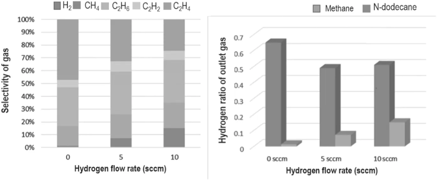
Figure 7.Diagram of the outlet gas composition under different hydrogen flows.

Table 1.Graphene mass loading.
The comparison of the graphene between methane and n-dodecane is consistent with the effects and conclusions caused by the different reaction conditions described above.N-dodecane requires more energy and more collisions of high-energy particles when the C-C bond and C-H bond are broken due to its large molecular weight. At the same time,the proportion of carbon atoms in n-dodecane is larger, and the specific gravity of hydrogen atoms is smaller. Therefore,compared with methane, the reaction produces relatively few active groups such as CnHx, especially decreasing raw materials such as C2and CH that are used for graphene growth. The reduced raw material causes insufficient hydrocarbon feedstock to bond to the nucleation sites on the Ni foam,explaining the lower yield of graphene obtained from n-dodecane in the table.
3.3.2. Gaseous product analysis. We can also study the action mechanism of the reactive groups in the ICP cracking process by analyzing the components of the outlet gas. This analysis occurs because the reactive groups not only deposit and grow as solid products, but directly collide with each other and produce small molecular gases.
By analyzing the outlet gas(i.e.the cracked gas product),it can be found that the gas phase products below C2mainly include CH4,C2H2,C2H4,C2H6and H2.Because hydrogen as a reaction gas directly affects the reaction and changes the final outlet gas composition,the change of the composition of the outlet gas under different hydrogen flow rates is the main focus.
As shown in figure 7, it is worth noting that during the cracking process of n-dodecane,the content of hydrogen in the outlet gas is positively correlated with the flow rate of the inlet hydrogen, while in the methane cracking process, the outlet hydrogen declines and eventually stabilizes. Meanwhile, the proportion of hydrogen in the outlet gas is above 50% in the methane cracking process,while the proportion of hydrogen in the n-dodecane cracking process ranges from 1.3%-15.1%,which is much lower than the former. This outcome may be caused by the different cracking mechanisms of n-dodecane and methane. The carbon hydrogen ratio of methane (CH4) is 1:4, while n-dodecane (C12H26) is 6:13. Therefore, under the action of high-energy electrons in the plasma,methane will be cleaved to obtain relatively equal C2radicals and H radicals.In contrast, n-dodecane will produce fewer H radicals and more CnHxgroups, reducing the probability of hydrogen molecules being generated by collisions between H radicals. Combined with the etching effect of hydrogen on the surface structure of the material, hydrogen has a more prominent role in the process of preparing carbon materials or graphene from liquid hydrocarbons. Reasonable hydrogen content may effectively improve the quality of carbon materials.
At the same time that the gaseous products below C2(CH4,C2H2,C2H4and C2H6)can be detected,the proportion of C2H2is low, less than 9%. The ratio of CH4, C2H4and C2H6is higher than that of C2H2. The ratio of CH4and C2H6is basically not affected by hydrogen flow, while the proportion of C2H4decreases with the increase in hydrogen flow.This outcome indicates that there is a parallel competition in the reaction of small molecules, and the hydrogen of the raw material will have a certain influence on this balance. Among them, C2H2and C2H4can form abundant nucleation points on the surface of the Ni foam,and they are the most important raw materials for carbon material growth. C2H4and C2H6can also continue to collide with high-energy electrons,excited Ar and H radicals to form basic constituent units of graphene, such as C2radicals and CnHx.
3.3.3. Discussion on the uncertainty analysis. The uncertainty error may exist in some aspect of the experiment, for example, the pressure change of the gas path may cause unsteady airflow or the change of the voltage could lead to instability of the plasma region.Besides,due to the equipment limitation of the input power, the n-dodecane may not be effectively cracked to form graphene. In other words, the cracking rate with higher input power may have different outcomes, and this is the basis for further exploration.
4. Conclusion
In the present research, carbon doping is prepared by plasma cracking using n-dodecane as a carbon source. By exploring various conditions,it can be found that the applied input power of the plasma will cause differences in the degree of n-dodecane cracking, and different reactive groups will grow different carbon materials.Hydrogen could etch the surface of the carbon material in the plasma region, and argon gas can form argon radicals to transfer energy, but too much will reduce plasma energy efficiency. Cluster-like carbon particles may be formed under an excessive injection rate.The reaction temperature can reduce the required plasma input power.However, the structure of the carbon material in this paper is also directly affected by temperature. The morphology of VG changes from a point-like linear distribution to a lamellar structure and then to a spherical particle cluster with increasing temperature. As investigated above, the favorable reaction temperature for growth of the graphene structure is 800°C.
In addition, from the results of Raman spectroscopy, we found that graphene nanowalls prepared from n-dodecane and methane have very similar crystal and defect structures. The relative intensity of the graphene D peak and G peak ID/IGprepared by n-dodecane is approximately 1.55, and the relative intensity of the 2D peak and G peak I2D/IGis approximately 0.48, indicating that the graphene has a rich defect structure and high degree of graphitization, respectively.
Regarding the cracking effect of RF ICP on n-dodecane and methane under similar operating conditions,the cracking rate of n-dodecane is only 6%-7%, which is approximately half of that obtained from methane. The detection results of the outlet gas indicate that the gaseous products below C2mainly include CH4, C2H2, C2H4, C2H6and H2. Among them, the proportion of hydrogen in the outlet gas of n-dodecane cracking ranges from 1.3%-15.1%, which is much smaller than that obtained from methane cracking(approximately 50%). The proportion of C2H2is relatively low, not higher than 9%, while the ratio of CH4, C2H4and C2H6is higher than that of C2H2. In addition, the proportion of CH4and C2H6is basically not affected by hydrogen flow,while the proportion of C2H4decreases with the increase of hydrogen flow.
 Plasma Science and Technology2020年2期
- Plasma Science and Technology的其它文章
- Analysis of the characteristics of the plasma of an RF driven ion source for a neutral beam injector
- Application of persulfate in low-temperature atmospheric-pressure plasma jet for enhanced treatment of onychomycosis
- Magnetic field enhanced radio frequency ion source and its application for Siincorporation diamond-like carbon film preparation
- Microwave frequency downshift in the timevarying collision plasma
- Comparison of Reynolds average Navier-Stokes turbulence models in numerical simulations of the DC arc plasma torch
- Effects of fast ions produced by ICRF heating on the pressure at EAST
