
Prediction of cutting forces in flank milling of parts with non-developable ruled surfaces
2019-08-13 02:22:30LipingWANGHoSILihengGU
CHINESE JOURNAL OF AERONAUTICS 2019年7期
Liping WANG ,Ho SI ,*,Liheng GU ,b
a Department of Mechanical Engineering,Tsinghua University,Beijing 100084,China
b Beijing Beiyi Machine Tool Co.Ltd.,Beijing 101300,China
KEYWORDS Chip thickness;Cutting force;Five-axis flank milling;Machining;Ruled surface
Abstract Predicting the cutting forces required for five-axis flank milling is a challenging task due to the difficulties involved in determining the Undeformed Chip Thickness(UCT)and Cutter-Workpiece Engagement(CWE).To solve these problems,this paper presents a new mechanistic cutting force model based on the geometrical analysis of a flank milling process.In the model,the part feature and corresponding cutting location data are taken as input information.The UCT considering cutter runout is calculated according to the instantaneous feed rate of the element cutting edges.A solid-discrete-based method is used to precisely and efficiently identify the CWE between the end mill and the surface being machined.Then,after calibrating the specific force coefficients,the mechanistic milling force can be obtained.During the validation process,two practical operations,three-axis flank milling of a vertical surface and five-axis flank milling of a nondevelopable ruled surface,are conducted.Comparisons between predicted and measured cutting forces demonstrate the reliability of the proposed cutting force model.
1.Introduction
Aerospace structural parts with non-developable ruled surfaces are widely used in the modern aviation industry.Fiveaxis flank milling with a flat-end mill is the main processing method for manufacturing such components.1As one of the necessary and important technologies that analyze a five-axis milling process,cutting force predictions are critical for deformation compensation,chatter control,and fixture design.During a five-axis milling process,ruled surfaces can be machined with great convenience,as this process has two more degrees of freedom than that of normal three-axis machining.2However,determining the Undeformed Chip Thickness (UCT)3and Cutter-Workpiece Engagement (CWE)4becomes difficult when using two additional axes.
There are numerous cutting force models for three-axis machining.Wei et al.5calculated the cutting forces in ballend milling of a sculptured surface with a Z-level contouring tool path,and discretized the machining process at feed intervals per tooth along the tool path.Gao et al.6identified the cutting force coefficients in a three-axis milling process,and a traditional coefficient identification method was improved using the cubic fitting method for given cutting conditions.Wu et al.7presented a cutting force model for circular end milling processes,which accounts for the effect of the curvature of the tool path on the chip thickness as well as the entry and exit angles.Zhang et al.8predicted the cutting forces for peripheral milling of a non-developable curved surface,and accounted for the cutter runout when calculating the UCT,which further improved the simulation accuracy.Based on these results,several researchers have considered the two additional degrees of freedom and predicted the cutting forces for a five-axis machining process.Ferry and Altintas9calculated the cutting forces for five-axis flank milling of jet engine impellers using a simplified expression for the UCT(fsinθ).In this process,the total velocity at each tool element is split into horizontal and vertical feed components which are used to determine the UCT along the cutting edge.Li et al.10used the classical UCT model to predict the cutting forces during a five-axis milling process considering the cutter runout effect.Xu et al.11obtained the UCT with respect to a pre-defined tool coordinate system,and a generalized cutting force model for a fiveaxis milling process was built using this improved method.These studies often adopt the classical UCT model or an improved form of this model to predict the cutting force for a five-axis machining process.However,this UCT model can only achieve a high simulation accuracy for three-axis milling with a linear tool path.For a curved tool path,this model cannot precisely predict the cutting forces.To solve this problem,Guo et al.12proposed an analytical model to describe the sweep surface of the cutting edge during a five-axis milling process,and the UCT was calculated according to the real kinematic trajectory of the cutting edges. Sun et al.13also established a UCT model for a continuously changing cutter axis orientation using the sweep traces of the cutter edges.These methods have proven highly accurate,but their processes are computationally burdensome and timeconsuming.
The extraction of the instantaneous CWE is another key factor for predicting the cutting forces for a five-axis machining process.With the help of commercial computer-aided manufacturing(CAM)software,the solid modeling method can accurately identify the overlap between a tool and a workpiece.Chiou et al.14presented a sweeping envelope method to predict the tool position in a five-axis milling process,and obtained a closed form of the swept profile.Yang et al.15proposed a solid trimming method to determine the CWE for multi-axis milling.Aras et al.16replaced the removal volume with the in-process workpiece for extracting the CWE,which is an extension of the classical solid model. Through logical operations, the CWE can be accurately extracted using the solid modeling method.However,this process requires the development of CAM software,which greatly limits the applicability of such a method.Several discrete modeling methods have been established to avoid the disadvantages of the solid modeling method.Kim et al.17firstly used a Z-map algorithm to extract the CWE for ball-end milling of sculptured surfaces.Wei et al.18developed a modified Z-map method to calculate the mesh position and Z-coordinates of a tool scanning surface according to the tool path and initial tool scanning boundary.Roth et al.19used an adaptive and local depth buffer to calculate the CWE for five-axis milling processes.Generally,the calculation process of the discrete modeling method is typically simpler than that of the solid modeling method.However,the accuracy of the discrete modeling method depends on the discrete density,meaning that an accurate computation of the CWE often requires considerable storage memory and has high computational requirements.
This paper proposes a new model for predicting the cutting forces during five-axis flank milling of non-developable ruled surfaces with a cylindrical cutter.The comprehensive effects of the spatial tool motion,workpiece geometry,and cutter runout are considered in this cutting force model.The remainder of this paper is organized as follows. A review of the related literature is presented in Section 1.Then,a summary of the basic modeling approach is provided in Section 2. Based on the geometrical analysis of the five-axis flank milling process,the UCT and instantaneous CWE are determined in Section 3.Machining process mechanics are applied to calculate the predicted cutting forces in Section 4.In Section 5,specific cutting force experiments are conducted,and comparisons between simulation and experimental results are used to verify the effectiveness of the proposed model.Finally,conclusions are drawn in Section 6.
2.Basic method
The overall procedure to model the cutting forces in a five-axis flank milling operation is illustrated in Fig.1.When the cutting location data,cutter geometry,and CAD model of a workpiece are used as the inputs to the model,a geometrical analysis of the milling process is conducted to obtain the essential cutting geometry features,including the UCT and instantaneous CWE for calculating the cutting forces.Then,along with the identified cutting force coefficients,a mechanistic cutting force model is used to predict the cutting forces during the five-axis flank milling process.
3.Geometrical analysis of five-axis flank milling
3.1.Coordinate frames
To accurately describe the complex spatial motion of the cutting tool during the five-axis flank milling process,it is necessary to establish a Workpiece Coordinate System(WCS)and a Tool Coordinate System(TCS).Both of them are Cartesian coordinate systems.The WCS is a fixed coordinate system and composed of three axes X,Y,and Z.The origin of the WCS can be arbitrarily selected on the surface of the workpiece.The coordinate axis vector of the WCS is consistent with the cutting force-measuring device,which is convenient for subsequent milling force analysis.The TCS is a moving coordinate system and comprises three coordinate axes U,V,and W.The origin of the TCS is located at the tool tip point.Its W-axis is along the tool axis,V-axis is the normal vector of the machined surface,and U-axis obeys the right-hand rule.Obviously,the origin and axial directions of the TCS change continuously in the five-axis milling process.
A schematic used to establish the TCS for a certain cutting location is shown in Fig.2.Using CAM software,programmers can easily write multi-axis machining programs for complex parts and generate Cutter Location Source(CLS)files.A CLS file contains cutting location information at each tool position point during the machining process,including the tool tip coordinates T(xt,yt,zt), unit tool axis vector W=(Wx,Wy,Wz), and contact point coordinates C(xc,yc,zc).The contact point refers to the intersection of the tool generatrix and the tool bottom contour.Thus,the V-axis vector V=(Vx,Vy,Vz) and U-axis vector U=(Ux,Uy,Uz)can be calculated based on the cutting location information as

and

where i,j,and k represent the unit vectors of X-,Y-,and Zaxes, respectively.A homogeneous transformation matrix
WCSTTCSis defined to represent the mapping of position vectors from the TCS to the WCS,which can be expressed as

where u,v,and w represent coordinates in the TCS,and
3.2.Undeformed chip thickness
Taking a cylindrical end mill with uniformly spaced teeth as the research object,the radial immersion angle of the j-th cutting edge varies with the elevation w as

where φsis the spindle rotation angle;φp=2π/Nfdenotes the pitch angle for a cutter; Nfis the number of teeth;φ(w)=(w tan β)/R represents the radial lag angle caused by the helical angle β,in which R is the radius of the cutter.
The tool surface normal is an important parameter for calculating the UCT.In the TCS,the arbitrary point A(ua,va,wa)and corresponding surface normal na=(na,u,na,v,na,w)of the cutter can be expressed as

and

The instantaneous feed direction at the arbitrary point A is another important parameter.During processing of vertical sidewalls,the cutting tool moves in a straight line,so the feed vector of any point on the cutting edge is consistent with the tool tip point.However,for non-developable ruled surface machining,the tool moves freely in space,and each point on the cutter envelope has a different feed rate.The feed vector of any point on the cutting edge can be calculated according to the positions of the cutter at two adjacent cutting locations,as shown in Fig.3.
The TCSs of two adjacent cutter locations are denoted asrespectively.The feed vectorat the tool tip point Tican be calculated directly with the coordinate information from the CLS as follows:

Fig.2 Establishment of the TCS.

Fig.3 Feed vector of an arbitrary cutting edge point.

The coordinates of an arbitrary point A in(TCS)iand(TCS)i+1are expressed asandrespectively. Then, using the mapping relationship described in Eq.(9),the coordinates of point Ai+1are transformed into the(TCS)ias


Based on the above expressions,the instantaneous UCT of the arbitrary point is determined as

where fzis the feed per tooth.
In addition,manufacturing and installation errors always exist during an actual milling process.Misalignment between the tool geometric center and tool rotation center is known as cutter runout.The cutter runout will change the instantaneous UCT of the cutting edge and influence the prediction of the milling force.Li et al.10defined the cutter runout using the eccentric distance ρ and the eccentric angle λ,as shown in Fig.4.In this figure,T and T'are actual and ideal tool tip points,respectively.Considering the influence of the cutter runout,the instantaneous UCT of the cutting edge can be further expressed as
where

3.3.Cutter-workpiece engagement

Fig.4 Schematic diagram of the cutter runout.
The immersion feature between a cutter and a workpiece in a multi-axis milling process is more complex than that in threeaxis machining.In this work,a solid-discrete-based method20is used to extract the instantaneous CWE in five-axis flank milling,where‘‘solid”refers to the update of the workpiece model using a Boolean operation and‘‘discrete”refers to the acquisition of point cloud data from the workpiece surface for calculating the CWE.The CWE extraction procedures can be summarized as follows.(1)Extract the point cloud data from the surface to be machined and determine whether the point set is suitable for the current cutting location according to the instantaneous tool position.(2)Divide the cutting tool into several tool elements along the axis,take the vertical distance to the tool axis and the axial extent of the tool element as the limiting conditions,and traverse each tool element to extract the coordinate points near the tool profile and form a possible CWE.(3)Trim the possible CWE using the filterand generate an exact CWE.This method enables a rapid calculation of the CWE at any cutter location with only a single extraction of point cloud data,and its advantages have been verified in Ref.20.
4.Process mechanics for five-axis flank milling
4.1.Cutting force model
The cutting force model most commonly used for milling processes was introduced in Ref.9.In this model,the mechanistic cutting forces are represented by two basic factors:shearing and edge effects.Six cutting force coefficients are defined to identify different cutter geometries and workpiece materials under specific cutting conditions.Then,the cutting forces can be calculated based on the six force coefficients,cut thickness,and cutter immersion data.
In particular,for each element of the j-th cutting edge,three differential cutting forces-tangential(dFt,j),radial(dFr,j),and axial(dFa,j)-at an arbitrary radial immersion angle φjcan be expressed as follows:

where Ktc,Krc,and Kacare the shear cutting coefficients;Kte,Kre,and Kaeare the edge cutting coefficients;db is the chip width in each tool element,particularly db=dw for the flatend mill;dS=dw/cos β is the length of the elemental cutting edge;δj(φj)is a rectangular window function that takes a value of one when the element is engaged in machining and is zero otherwise,that is,

where φst(w)and φex(w)are the start and exit angles for the cutting edge element with respect to the w coordinate,respectively, and can be calculated from the extracted CWE.Through coordinate transformation, the tangential, radial,and axial differential cutting forces can be described in the TCS as

where

The total cutting forces acting on the cutting tool are calculated by integrating the differential forces along the engaged edge elements and summing the contributions of the cutter flutes as follows:

where w1and w2are the lower and upper axial engagement limits of the cutting edge,respectively.
Because the measured cutting forces are obtained by a dynamometer in the experiment,the simulated cutting forces must be transformed into the WCS to verify the correctness of the cutting force model.This process can be evaluated by

where

4.2.Cutting coefficient calibration
Accurate cutting force coefficients are essential for the reliability of the predicted cutting forces.Due to the existences of the bottom edge and wiper,the cutting coefficients of the tool element close to the bottom often appear inconsistent.Therefore,quadratic polynomial shear coefficients and constant edge coefficients are adopted in the tool section with height values less than 2 mm.The rationality of this choice has been confirmed in Ref.21.The expressions of the three polynomials are as follows:

To simplify the calibration process,a set of slot milling experiments is conducted at different feed rates and with a constant axial cutting depth to obtain actual cutting force data.Then,the average cutting forces in the U,V,and W directions are calculated to identify the specific cutting coefficients.The analytical equations for the average cutting forces per tooth period are as follows:

In fact,the adverse effect of the cutter runout can be avoided by using the average cutting force,meaning that the UCT in the calibration model can be replaced by

Meanwhile,for the slot milling process,φst=0,φex=π,w1=0,and w2=ap,where apdenotes the axial cutting depth.Thus,the connections between the average cutting forces and specific cutting coefficients can be expressed as follows:

where

5.Simulation and experimental results
In this section,two types of machining experiments are performed:one to compare the measured and predicted cutting forces in straight-line milling throughout one rotational revolution of a cutter;the other to investigate the capabilities of the proposed model in five-axis flank milling of a nondevelopable ruled surface.All the experiments are conducted on a five-axis machining center DMU 60 MONOBLOCK with a constant spindle speed of 1000 r/min.A three-component dynamometer(Kistler type 9257B)is mounted on the worktable to measure the instantaneous cutting force components in the Xm,Ym,and Zmdirections of the measuring coordinate system(see Fig.9).The sampling rate is set to be 6 kHz.In these experiments,a cemented carbide flat-end mill with a diameter of 16 mm,a helix angle of 45°,and three flutes is used.The material of the workpiece is 7075 aluminum alloy.
5.1.Calibration of the cutting force coefficients
Several groups of slot milling tests with axial cutting depths of 0.2-2 mm and feed rate intervals of 120-280 mm/min are used to identify the cutting coefficients for the lower tool section.In these tests,the coordinate axes of the TCS and the WCS are aligned.A prefinished aluminum plate blank is taken as the workpiece and connected to the dynamometer by four bolts.According to the calibration model described in Section 4.2, the edge coefficients are Kte=23.8 N/mm,Kre=30.2 N/mm,and Kae=11.2 N/mm,and the shear coefficients are

The cutting force coefficients of the upper tool section are identified using the method described in Ref.22.The calibration results are Ktc=727.5 N/mm2, Krc=325.8 N/mm2,Kac=194.2 N/mm2, Kte=20.9 N/mm, Kre=35.2 N/mm,and Kae=10.2 N/mm.
5.2.Verification of the cutting force for linear flank milling
To confirm the validity of the cutting coefficients,cutting force simulation and the corresponding experiment for a linear flank milling process are performed.The spindle speed is 1000 r/min,the feed rate is 200 mm/min, the radial cutting depth is 0.8 mm,and the axial cutting depth is 5 mm.Cutter runout parameters are obtained from experimental data using the method presented in Ref.22.The two runout parameters for the current cutter are ρ=0.008 mm and λ=39.65°.The predicted and measured cutting forces for one revolution of the cutter are shown in Fig.5.They are described under the measuring coordinate system of the dynamometer.The predicted cutting forces are similar to the experimental data,validating the proposed strategy.The maximum cutting force prediction error is approximately 4.6%in the X-and Y-directions.This difference may arise from machining vibrations,environmental influencing errors,and cutting force coefficient calculation errors.Moreover,measurement errors always exist in the Zdirection of the dynamometer;thus,the Z-axis force is ignored in the verification.
5.3.Verification of the cutting force for five-axis flank milling
The proposed cutting force model is validated using five-axis flank milling of a non-developable ruled surface.The surface is defined by two quasi-uniform cubic rational B-splines which are generated by two sets of control points Piand Qi.The geometric feature of the ruled surface is shown in Fig.6,and the coordinates of the control points are given in Table 1.According to the degree of curvature,the machined surface can be divided into close,flat,and open regions.The immersion statuses of these three regions have their own characteristics.
To study the influence of the surface curvature on the milling force,the procedures of the prediction model are performed for non-developable ruled surface machining with the same cutting parameters as in Section 5.2.There are 250 cutting locations in the machining process.The simulated tangent force at each cutting location is shown in Fig.7.It is evident that the milling force in the feed direction is sensitive to the geometric feature of the machined surface.Through marking the relative positions of the three surface regions,it can be seen that the tangent force in the close region has the maximum value,followed by that of the flat region,while the minimum value is in the open region.

Fig.5 Predicted and measured cutting forces in linear flank milling.

Fig.6 Geometric feature of the ruled surface.
Considering the feature of the cutter-workpiece contact,the CWEs of these three regions are extracted and shown in Fig.8.Although their radial cutting depth and axial cutting depth are consistent during the milling process,the contact width in the close region is obviously larger than those in the flat and open regions.In such cases,the difference in the CWEs causes their immersion angles to be different, which leads to further changes in the cutting force calculation.
Based on the above analysis,several machining experiments are conducted to verify the reliability of the proposed cutting force model,as shown in Fig.9.These experiments are different from each other in their axial cutting depths from 5 mm to 20 mm.In this case,both the involved cutting tooth and the engaged tool-workpiece contact area can be considered.Other cutting parameters are a spindle speed of 1000 r/min,a feed rate of 200 mm/min,and a radial cutting depth of 0.8 mm.
In the case of an axial cutting depth of 5 mm,the milling forces for the non-developable ruled surface are predicted using the proposed model and transformed to the measuring coordinate system.Measurements capture complete variations of cutting forces over time.Because the performance of an operation can be measured well by checking the most critical situations,simulated cutting forces exhibit only the maximum/minimum cutting forces of each moment.5The predicted cutting forces correspond well with the measured results in both shape and magnitude,as shown in Fig.10.This phenomenon indicates that the proposed cutting force model can accurately predict the milling force in the five-axis flank milling process.The predicted cutting forces are slightly lower than the experimental data,which correspond with the linear flank milling results.Meanwhile,the smaller the measured values are,the more distinct the influences on the cutting forces by the environment are.The force-sources from the environment include the force-chatter,machine vibration,tool deflection,and so on.Reasonable selection of cutting parameters can effectively reduce the adverse effects of these factors on the measured forces.
Then,another comparison is shown in Fig.11,for which the axial cutting depth is 20 mm.Under this cutting condition,both of the two teeth can be involved in machining.It can be seen that the minimum value profile of the cutting forces in Fig.11 is similar to the maximum value profile of the milling force in Fig.10,which means that at least one cutter tooth participates in cutting all the time.Meanwhile,the maximum value profile of the milling force in Fig.11 is mainly causedby the second tooth.This comparison further testifies that the proposed cutting force model has ability to predict cutting forces in five-axis flank milling of a non-developable ruled surface accurately.

Table 1 Positions of the control points.

Fig.7 Tangent forces at different cutting locations.

Fig.8 CWEs from the close,flat,and open regions.

Fig.9 Five-axis flank milling experiment.
6.Conclusions
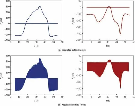
Fig.10 Predicted and measured cutting forces with an axial cutting depth of 5 mm.

Fig.11 Predicted and measured cutting forces with an axial cutting depth of 20 mm.
This paper presents a cutting force prediction model for fiveaxis flank milling of non-developable ruled surfaces.To predict the force,the issues of a varying UCT,varying cutter engagement,and consequent varying cutting forces generated during a milling process are addressed.A geometrical analysis of fiveaxis machining is conducted based on the cutting location information in the CLS.Instead of a circular approximation,the UCT is calculated considering the unique feed vector of each cutting edge element and the cutter runout effect.An efficient solid-discrete-based method is applied to extract the instantaneous CWE.
Simulation and validation experiments are conducted via machining aluminum 7075 with a cylindrical end mill.Results demonstrate that the part surface curvature significantly affects the immersion angle of the cutter and further influences the magnitude of the cutting forces.Predicted cutting forces correspond well with measurements in both shape and magnitude,confirming the reliability of the proposed model.
Acknowledgements
This study was co-supported by the Major National S&T Program(No.2014ZX04014-031)and the National Natural Science Foundation of China(No.51225503).
Appendix A.Supplementary data
Supplementary data associated with this article can be found,in the online version,at https://doi.org/10.1016/j.cja.2018.07.017.
 CHINESE JOURNAL OF AERONAUTICS2019年7期
- CHINESE JOURNAL OF AERONAUTICS的其它文章
- Guide for Authors
- Configuration synthesis of planar folded and common overconstrained spatial rectangular pyramid deployable truss units
- A new error-controllable method for smoothing the G01 commands
- Electrochemical trepanning with uniform electrolyte flow around the entire blade profile
- Thermal-structure coupling analysis and multiobjective optimization of motor rotor in MSPMSM
- Lightweight structure of a phase-change thermal controller based on lattice cells manufactured by SLM