
Electrochemical trepanning with uniform electrolyte flow around the entire blade profile
2019-08-13 02:22:16DongZHUTingyuXUEXingyanHUZhouzhiGU
CHINESE JOURNAL OF AERONAUTICS 2019年7期
Dong ZHU,Tingyu XUE,Xingyan HU,Zhouzhi GU
College of Mechanical and Electrical Engineering,Nanjing University of Aeronautics and Astronautics,Nanjing 210016,China
KEYWORDS Diffuser;Electrochemical machining;Flow;Roughness;Taper
Abstract In the traditional machining process for diffusers,blades are easily deformed,and methods suffer from high tool wear and low efficiency.Electrochemical machining(ECM)possesses unique advantages when applied to these difficult-to-machine materials.In the ECM process,the flow field plays a crucial role.Here,an electrolyte flow mode that supplies uniform flow around the entire blade profile was adopted for electrochemical trepanning of diffusers.Various flow rates were employed to obtain the optimal flow field.Simulations were conducted using ANSYS software,and results indicated that increasing the flow rate substantially afforded a more uniform flow field.A series of experiments was then performed,and results revealed that increasing the flow rate greatly improved both the machining efficiency and the surface quality of the diffusers.The maximum feeding rate of the cathode reached 4 mm/min,the blade taper of the concave part decreased to 0.02,and the blade roughness was reduced to 1.216 μm.The results of this study demonstrated the high feasibility of this method and its potential for machining other complex components for engineering applications.
1.Introduction
Vaned diffusers are the key components of engine compressors of helicopter turboshafts.1-3They are typically fabricated from difficult-to-machine materials,and their blades are thin and easily deformed;consequently,their manufacture by traditional machining techniques is relatively difficult.4Electrochemical machining(ECM)is a non-traditional machining method that possesses certain advantages,for example,it can reduce wastage of the tool electrode and be applied to processing of thin-walled components without cutting stress.5,6ECM has been widely applied in a variety of industries,such as aerospace,molding,and medical sectors,7-9and is a promising technique for diffuser manufacture.
In the ECM process,the condition of the flow field is the key factor affecting the stability.10,11An appropriate flow field improves the stability of the process and also enhances the machining efficiency and accuracy.Over recent years,research on flow field design in ECM has received much attention.Zhu et al.proposed a W-shaped electrolyte flow mode and reported that it enhanced the machining accuracy and surface quality of a blade.12,13Xu et al.compared three flow field models and demonstrated that using the Π-shaped flow mode enhanced the quality,stability,and efficiency of ECM of a blisk cascade passage.14Zhu et al.later proposed a dynamic additional flow mode to eliminate regions with bad flushing conditions in the ECM process of a blisk cascade passage,which reduced the surface roughness.15Qu et al. introduced a progressivepressure flow mode to decrease the effect of on-way resistance and successfully improved the machining efficiency and accuracy.16Fang et al.analyzed the effects of pulsating electrolyte flow on the gas fraction,heat transfer,material removal rate,and surface profile.17Skoczypiec proposed an ultrasonically assisted ECM method, in which ultrasonic vibration of the cathode was employed to improve the electrolyte flow in the machining gap.18Tang and Gan analyzed the effect of the cathode orifice on the electrolyte flow line to reduce the cathode design period and costs.19Wu et al.proposed the use of a hollow cathode structure and radial flow to improve the flow rate stability and enhance the removal of generated heat.20
In this study,electrochemical trepanning with a uniform flow supplied around the entire blade profile was employed as the machining method.A high flow rate was applied to improve the stability of the flow field.The proposed method was evaluated using a combination of simulations and experiments.
2.Description of electrochemical trepanning method
In this study,electrochemical trepanning was selected as the machining method to fabricate an axial blade with a constant section.A schematic diagram of the traditional electrochemical trepanning method is presented in Fig.1(a).In electrochemical trepanning,the tool cathode is designed to shape the blade,and an insulating chamber is installed inside the cathode base to protect the machined part.In the typical method,a forward flow mode is applied as the electrolyte flow mode.The electrolyte enters from the gap between the cathode base and the insulating chamber,passes through the gap between the insulating chamber and the inside of the tool cathode,and eventually exits from the outlet near the processing area in front of the tool cathode,carrying away the dissolved metal and heat to ensure a smooth operation.In this traditional flow mode,the electrolyte crashes against the blade and is divided into several paths to flow through the convex part channel,concave part channel,leading edge channel,and trailing edge channel.The streamlines at the electrolyte inlet are mussy.In addition,because the electrolyte that is supplied to different channels is random,the amount of electrolyte is variable and uncontrollable,leading to uneven flow in the machining area.These two phenomena may cause process instability and low machining efficiency.
In an effort to overcome the shortcomings of the traditional flow mode,a new flow mode was designed,in which a bladeshaped isolation was used to divert the electrolyte flow into different channels(Fig.1(b)).In this mode,the electrolyte flows along the entire profile of the blade,including the trailing and leading edges.The two key advantages of this flow mode are as follows:(1)as the electrolyte flow is divided according to the blade shape and there is a long flow path to stabilize the flow,the electrolyte is supplied evenly to all of the channels;(2)the gap between the isolation and the cathode can be adjusted according to the distribution of the flow field in the inter-electrode gap,so the flow situation can be enhanced.Consequently,the new flow mode is very controllable and affords uniform electrolyte flow during the entire process.

Fig.1 Schematic diagrams of the traditional forward and new flow modes in electrochemical trepanning.
Regions of low flow velocity,especially those without liquid in the flow field of the processing area,are severely detrimental,as they prevent further ECM from occurring.Electrolyte velocity is one of the most important factors in electrochemical trepanning of diffusers,as it not only ensures a turbulent flow,but also controls the temperature rise.In terms of the turbulent flow and minimizing the temperature increase,the electrolyte velocity should satisfy the following equations16,10:

where u is the electrolyte velocity at the inlet,v is the coefficient of kinematic viscosity,Dhis the hydraulic diameter,i is the current density,ρ is the electrolyte density,κ0is the electrolyte conductivity,C is the specific heat capacity of the electrolyte,ΔTeis the temperature increase,and L is the flow length.
From Eq.(1),the electrolyte velocity must be high enough to ensure a turbulent flow.Similarly,from Eq.(2),the electrolyte velocity should be high enough to minimize the temperature increase.The electrolyte velocity is directly determined by the electrolyte flow rate as

where Q is the electrolyte flow rate,S is the area of the inlet,and u0is the velocity of the electrolyte at the inlet.
Increasing the electrolyte flow rate leads to a higher electrolyte velocity at the inlet.It is clear that the electrolyte velocity in the processing area will also be increased with an increased flow rate.Therefore,in this study,electrochemical trepanning was investigated with various electrolyte flow rates.
3.Simulations
3.1.Establishment of a 3D flow field model and a mathematical model
To simulate the electrochemical trepanning process using the new flow mode,a 3D flow field model including the inlet,electrolyte flow channel,outline of the cathode,and side gap was established,as depicted in Fig.2.The flow rate was varied to evaluate its influence on the flow field in the processing area.The flow rate at the inlet was increased from 0.5 to 7.5 m3/h,and the specific values were 0.5,1,1.5,2,2.5,3,3.5,4.5,and 7.5 m3/h.The pressure at the outlet was defined as zero.The area of the inlet was 93.55 mm2,and it can be seen from Eq.(3)that the inlet velocity increases linearly with an increasing flow rate.Section A,which was positioned in the middle of the front gap of the flow field,was selected to analyze the distribution of the flow field.

Fig.2 3D flow field model.
To exactly describe the parameters of the flow field during electrochemical trepanning of a diffuser,the re-normalization group(RNG)k-ε model was applied in the simulation.20The turbulence kinetic energy and dissipation rate equations are as follows:
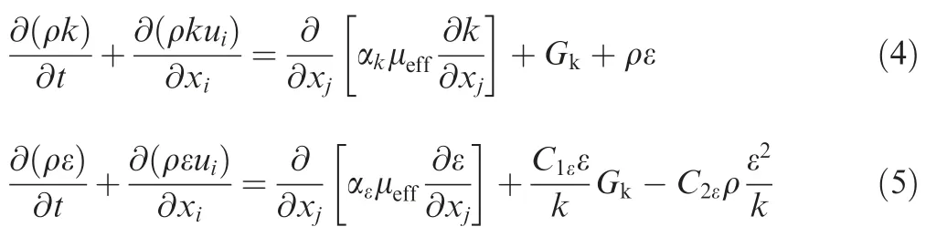
where k is the turbulence kinetic energy,t is the time,xiand xjare the displacements in the i and j directions,respectively,ε is the turbulence dissipation rate,uiis the average velocity,μeffis the effective viscosity,μeff=μ+μt,and Gkis the generation of turbulence kinetic energy caused by the average velocity gradient.The turbulent viscosity,μt,is determined by Eq.(6).αk,αε,C1ε,C2ε,and Cμare empirical constants,and their values are: αk=αε=1.39, C1ε=1.42, C2ε=1.68, and Cμ=0.0845.

The RNG k-ε model takes full consideration of techniques derived from strict statistics,including turbulent eddies.Furthermore,this model can handle streamline flow with a large bending degree,and is suitable for the complex streamline situations considered in this study.
3.2.Flow field simulations and analysis
Using the flow field model described in the previous section,simulations were performed under different flows using ANSYS software.The partial vectors of the electrolyte velocity in section A with an increasing flow rate obtained from the simulations are depicted in Fig.3.
The following conclusions can be drawn from the simulations.(1)Upon increasing the flow rate from 0.5 m3/h to 7.5 m3/h,the electrolyte velocity exhibited an overall improvement,and the distribution of the flow field became better.Furthermore,118712 nodes were sampled on section A,and their velocities were obtained after postprocessing. The average velocities were about 5 and 71 m/s at flow rates of 0.5 and 7.5 m3/h,respectively.(2)The electrolyte velocity in the vicinity of the trailing edge was comparatively low,especially at flow rates of 0.5 and 1 m3/h,and the electrochemical trepanning process was expected to be hindered in this region;therefore,special attention should be paid to the electrolyte velocity at the trailing edge.At a flow rate of 0.5 m3/h,a lack of liquid zone near the trailing edge was especially prominent,and the velocity was less than 1 m/s, whereas at a flow rate of 7.5 m3/h, the velocity increased to approximately 30 m/s,which conforms to the requirements of electrochemical trepanning.Ultimately,it can be concluded that increasing the flow rate provides an effective mean for increasing the electrolyte velocity and improving the flow field uniformity.Therefore,electrochemical trepanning experiments using different flow rates were performed to verify the simulation results.

Fig.3 Distributions of velocity vectors in Section A at various flow rates.
4.Experiments and analysis
4.1.Preparation and process of experiments
In an effort to validate the flow field simulations using different flow rates,ECM experiments were conducted in which the axial blade of a diffuser was machined using a self-developed ECM machining tool.A cathode was designed for use in electrochemical trepanning with the forward flow mode.The cathode base material was stainless steel 304. The insulating chamber was fabricated from epoxy resin and fixed inside the cathode base.The cathode was fabricated from tungstencopper alloy,which is capable of resisting the sparks that occur during the machining process.The model and experimental setup used for electrochemical trepanning of the blade are shown in Fig. 4. The processing area was approximately 4.734 cm2.The workpiece sample had an exradius of 242 mm and a thickness of 37 mm,and was fabricated from a nickelbased superalloy.The electrochemical trepanning parameters are summarized in Table 1.
In this study,a series of experiments was conducted using different flow rates under the conditions described above,i.e.,to increase the feeding rate of the cathode(defined as vf).Owing to the equipment limitations of the experimental setup,the maximum possible flow rate was 4.5 m3/h.Flow rates of 1.0 m3/h,3.0 m3/h,and 4.5 m3/h were selected for the experiments.At each of these three flow rates,variation of the feeding rate of the cathode was investigated.The initial feeding rate was 0.5 mm/min,and the speed was gradually increased in intervals of 0.5 mm/min to explore the influence of the flow rate on the machining efficiency and quality of the resulting blade.

Fig.4 Model and experimental setup used for electrochemical trepanning of a blade.

Table 1 Electrochemical trepanning parameters.
4.2.Analysis of experimental results
4.2.1.Influence of increasing flow rate on feeding rate limit
The experiments revealed that the limit of the feeding rate varied under different flow rates.(1)At a flow rate of 1.0 m3/h,the machining process remained stable when the feeding rate was 0.5 mm/min, whereas at a feeding rate of 1.0 mm/min, a short-circuit phenomenon occurred in the processing area.The machining process remained stable upon decreasing the feeding rate to 0.75 mm/min.The current I increased steadily and finally reached a balance. Thus, at a flow rate of 1.0 m3/h,the feeding rate limit was 0.75 mm/min.(2)At a flow rate of 3.0 m3/h,feeding rates of 0.5,0.75,1.0,1.5,2.0,2.5,3.0,and 3.5 mm/min were successively investigated.Under these conditions,the machining process smoothly achieved stability,whereas the short-circuit phenomenon occurred at a feeding rate of 4.0 or 3.75 mm/min,so the feeding rate limit was 3.5 mm/min.(3)At a flow rate of 4.5 m3/h,the feeding rate limit was 4.0 mm/min.Therefore,these experiments demonstrated that the feeding rate limit increased from 0.75 to 4.0 mm/min when the flow rate was increased from 1.0 to 4.5 m3/h,indicating that the flow field in the processing area became more stable and thus verifying the effectiveness of the flow field simulations.The results of the machining stability at different flow rates and feeding rates are summarized in Table 2.
When the feeding rate reached the upper limit for a particular flow rate,a short circuit always occurred,and the workpiece and the cathode were damaged. This discharge typically occurred at the trailing edge of the blade.This location at which the short circuit occurred during the experiments is consistent with the flow field simulation results discussed in Section 3.2,which revealed a region of low flow velocity at the trailing edge of the blade when the flow rate at the inlet was low.

Table 2 Machining stability at different flow rates and feeding rates.

Fig.5 Variation of the machining current with the feeding distance at different feeding rates and flow rates.
The variation current versus the feeding distance for different feeding rates and flow rates is shown in Fig.5.The following observations can be made.(1)The machining current increased from approximately 170 A and rapidly achieved a balance.(2)The balanced current increased with an increasing feeding rate and finally reached 1500 A at a feeding rate of 4 mm/min and a flow rate of 4.5 m3/h.(3)Regardless of the feeding rate,the current remained stable when the feeding distance exceeded approximately 1 mm.This indicates that the process had reached stability at that time.

Fig.6 Photographs of processed samples obtained using various flow rates and feeding rates.

Fig.7 Partial blades of a sector machined at different feeding rates with a flow rate of 3 m3/h and cross section of blades machined at feeding rates of 0.5 and 4 mm/min.
Photographs of processed samples obtained using different feeding rates and flow rates are presented in Fig.6.The following characteristics can be observed.(1)At a flow rate of 1.0 m3/h,the quality of the blade was poor.The leading and trailing edges of the blade were severely corroded,and the rear of the concave part exhibited a large taper.Moreover,the blade roughness was high,and the blade was relatively thin.(2)At a flow rate of 3.0 m3/h,the taper gradually diminished with an increasing feeding rate. At a feeding rate of 1.5 mm/min,a relatively complete outline of the leading and trailing edges of the blade was obtained,and the blade roughness was substantially improved. The sector machined at different feeding rates under this flow rate is shown in Fig.7(a).(3) At a flow rate of 4.5 m3/h and a feeding rate of 4 mm/min,the best results were obtained in terms of the blade taper and surface roughness.In addition,in order to observe variation of the blade thickness clearly,the cross sections in the middle of samples machined at feeding rates of 0.5 and 4 mm/min were measured by an optical microscope(Leica DVM 5000,Germany),which are presented in Fig.7(b).The thickness was larger and the side wall was straighter at a feeding rate of 4 mm/min.The results reveal that the corrosion on the side wall of the machined blade decreased significantly with an increase of the feeding rate.
4.2.2.Influence of increasing the feeding rate on the blade taper
The blade taper is one of the main evaluation criteria for axial blades,and a schematic diagram is presented in Fig.8.The taper can be defined as

where CTis the blade taper,H is the height of the machined blade,and X is the radial distance from the apex to the root of the machined blade.

Fig.8 Schematic diagram of the blade taper.
Machined blades obtained using different feeding rates and flow rates were measured,and the taper was calculated according to Eq.(7).Results are presented in Fig.9.The following observations can be made.(1)At a flow rate of 1.0 m3/h,the machined blade possessed a large taper.The taper values of the concave part were 0.24 and 0.14 when feeding rates were 0.5 and 0.75 mm/min,respectively.This indicates that the taper decreased substantially when the feeding rate was increased.(2)At a flow rate of 3.0 m3/h,the blade taper became increasingly smaller with an increasing feeding rate,and the minimum was achieved at a feeding rate of 3.0 mm/min.(3)At a flow rate of 4.5 m3/h,the blade taper of the concave part decreased from 0.22 to 0.02 when the feeding rate was increased from 0.5 mm/min to 4.0 mm/min.These results clearly demonstrate that the blade taper was improved with an increasing feeding rate at different flow rates.Increasing the flow rate led to an increase in the electrolyte velocity in the inter-electrode gap.Consequently,electrochemical products were rapidly removed from the reaction area,and the cathode feeding rate could be increased accordingly.Therefore,the second machining action on the machined blade was significantly reduced,leading to a small taper obtained for these samples.Furthermore,the blade taper was found to be similar when the same feeding rate was used,even at different flow rates.
4.2.3.Influence of increasing the feeding rate on the blade roughness
The variation of the blade roughness was also measured by a roughness tester(its type is MAHR PS1)for blades fabricated using different feeding rates and flow rates.Results are presented in Fig.10.The following observations can be made.(1)At a flow of 1.0 m3/h,the machined blade exhibited a high roughness,although this began to decrease when the feeding rate was increased from 0.5 mm/min to 0.75 mm/min.(2)At a flow of 3.0 m3/h,the blade roughness gradually decreased with an increasing feeding rate and reached the minimum at a feeding rate of 3 mm/min.(3)At a flow rate of 4.5 m3/h,the blade roughness decreased from 3.507 to 1.216 μm for the concave part and from 3.788 to 1.320 μm for the convex part.(4)At a given feeding rate,the flow rate exerted little influence on the blade roughness,the same as observed for the blade taper.These results reflect the fact that increasing the flow rate increased the electrolyte velocity and thus improved removal of material from the processing area,thereby permitting a higher feeding rate.The increased feeding rate then led to less second machining time on the machined blade,resulting in improved surface roughness and taper.

Fig.9 Variation of the blade taper with the feeding rate at different flow rates.

Fig.10 Variation of the blade roughness with the feeding rate at different flow rates.
5.Conclusions
(1)Electrochemical trepanning was applied to machining of diffusers,using a blade-shaped isolation to supply a uniform flow around the entire profile of a blade.
(2)A 3D flow field model was established and applied to simulate the effects of increasing the flow rate using the ANSYS software.Simulation results revealed that the flow velocity of the flow field increased significantly with an increasing flow rate,and the flow field distribution became more homogeneous.
(3)A series of experiments was performed to investigate machining of a diffuser using electrochemical trepanning.The feeding rate limit was found to greatly increase with an increasing flow rate,and the maximum feeding rate increased from 0.75 mm/min at a flow rate of 1.0 m3/h to 4.0 mm/min at a flow rate of 4.5 m3/h.In addition,the blade taper and surface roughness were clearly enhanced.At a flow rate of 4.5 m3/h,increasing the feeding rate from 0.5 to 4 mm/min afforded a decrease in the taper of the concave part from 0.22 to 0.02 and a decrease in the roughness of the concave part from Ra 3.507 to Ra 1.216 μm.The results of this study demonstrated that the machining efficiency and blade quality were greatly improved by using the proposed flow mode.
Acknowledgements
This study was co-supported by the National Natural Science Foundation of China(51675271),the Natural Science Foundation of Jiangsu Province (BK20171413), the Fundamental Research Funds for the Central Universities(NE 2017003),and the Qing Lan Project.
 CHINESE JOURNAL OF AERONAUTICS2019年7期
- CHINESE JOURNAL OF AERONAUTICS的其它文章
- Guide for Authors
- Prediction of cutting forces in flank milling of parts with non-developable ruled surfaces
- Configuration synthesis of planar folded and common overconstrained spatial rectangular pyramid deployable truss units
- A new error-controllable method for smoothing the G01 commands
- Thermal-structure coupling analysis and multiobjective optimization of motor rotor in MSPMSM
- Lightweight structure of a phase-change thermal controller based on lattice cells manufactured by SLM