
Configuration synthesis of planar folded and common overconstrained spatial rectangular pyramid deployable truss units
2019-08-13 02:22:28HuiYANGHongweiGUOYnWANGRongqingLIUZongqunDENG
CHINESE JOURNAL OF AERONAUTICS 2019年7期
Hui YANG ,Hongwei GUO ,Yn WANG ,Rongqing LIU ,Zongqun DENG
a College of Electrical Engineering and Automation,Anhui University,Hefei 230601,China
b State Key Laboratory Robotics and System,Harbin Institute of Technology,Harbin 150001,China
c China Electronics Technology Group Corporation No.38 Research,Hefei 230088,China
KEYWORDS Assembly SAR antenna;Common overconstraint;Deployable truss structure;Screw theory;Structural synthesis
Abstract Compared with non-overconstrained deployable units,overconstrained deployable units are widely used in space missions for their higher stiffness characteristics.Besides the performance of a three-step topological structural analysis and design of the rectangular pyramid deployable truss unit(PDTU),conducting a structural synthesis of an overconstrained deployable unit requires the determination of the relative position and direction of each kinematic axis.The structural synthesis of an overconstrained deployable unit is investigated based on screw theory and its topological structure.The possible overconstrained cases of the rectangular PDTUs are analyzed,and corresponding screw expressions are obtained.Thus,the rectangular PDTUs,which can be folded into a plane,are synthesized systemically,and a series of overconstrained rectangular PDTUs is obtained.Furthermore,the feasibility of the folded and deployed motions under one degree of freedom for those deployable units is verified in dynamical simulation by using ADAMS 2010.
1.Introduction
Deployable mechanisms are widely used in satellite synthetic aperture radar(SAR),solar arrays,space borne antennas and space exploratory missions.Applying modern mechanistic theory to describe and analyze the topological structure of the deployable mechanisms for modeling their structural synthesis and discovering new deployable mechanisms is of significant value in engineering and academic applications as well.You and Chen1-4improved the Bennett, Myard, and Bricard linkages by presenting a design and networking method of configuring the deployable mechanism by using single-loop overconstrained spatial linkages as the base unit and thus have,and a variety of spatial closed-loop overconstrained deployable mechanisms have been created.Gan and Pellegrino5proposed a numerical kinematic method for single closed-loop deployable mechanism.Medzmariashvili et al.6obtained a new variant of the deployable ring-shaped space antenna reflector by synthesizing ring-and umbrella-shaped deployable mechanisms.Korkmaz et al.7designed a 2-DOF 8R linkage for transformable hyper-structure.Moterolle et al.8proposed a numerical form finding of geotensoid tension truss for a network reflector,which can guarantee the key point position and tensioning force simultaneously.
Structural synthesis is an effective method of planar and spatial mechanism innovative design,and structural synthesis has been divided into three main groups in past decades9.The first group is the displacement subgroup based on structural synthesis.Specifically,Herve′10proposed twelve types of displacement subgroups.By using this method,the geometric condition for the mechanisms was elucidated.However,the mathematical method is complex,and hence the mathematical method is only for structural synthesis with displacement subgroup structures.Later,Angeles11,Rico12,Huang and Li13also synthesized the parallel manipulators based on displacement subgroups.The second group is based on the constraint screw principle,proposed by Huang and Li14.This synthesis method is a simple numerical linear operation and is suitable for general overconstrained and non-overconstrained mechanisms.However,the geometric conditions for the mechanisms are non-generic,and the instantaneous mechanisms need to be investigated.Fang15,16,Kong and Gosselin17made important improvements to this method.The third group is the kinematic synthesis.In this kinematic synthesis,Yang et al.18presented a position and orientation characteristics matrix.The problem with this group is that the mechanisms obtained by this method are not instantaneous.The physical meaning of its synthesis process is explicit and it is widely applied in engineering.However,compared with the former methods,its mathematical theory is incomplete.The kinematic synthesis also includes the GF synthesis method proposed by Gao et al.19and the linear transformations presented by Gogu20.
In this study,the application of the synthesis theory of the parallel manipulators to the deployable mechanisms with the aim of obtaining a new deployable mechanism is investigated.Based on screw theory,the conditions of the continuous folded and deployed movement are derived for the overconstrained deployable mechanisms according to the overconstrained power and the addition of overconstrained power that is equal to zero.The structural synthesis flowchart of the overconstrained deployable mechanism is proposed,a rectangular deployable mechanism under common constraint as a first-,second-and third-order wrench as well as a redundant constraint,are synthesized and a series of overconstrained rectangular deployable mechanisms is obtained.
2.Rectangular pyramid deployable truss structure
Design of a pyramid deployable truss structure (PDTS)includes three main assumptions:its spatial deployed state is a pyramidal structure,and its folded state is a planar structure;both folded and deployed states are stable;and PDTS is a lower mobility mechanism during the deployable and retraction phases.Weighted graph and kinematic chains were used to describe the intersection relationships of nodes and components in a conceptual configuration,respectively.Rectangular pyramid deployable truss unit(PDTU)includes five nodes and nine links,and its weight graph is a regular pentagon with all vertices located in the outer loop.This number is optimum because that all planes are consisted of triangles in deploying statue and are high stability.
A two-step topology structure synthesis and analysis approach for PDTU was proposed and applied to design PDTU in Ref.21-25.The conceptual configuration of PDTU was synthesized first.Weighted graph and weighted adjacency matrices were established to realize a topological description for PDTU.Graph properties were summarized to distinguish differences between PDTU and other types of structures.A procedure for synthesis conceptual configuration of PDTU was presented according to graph properties.The joint relationship of components in a PDTU was analyzed.Kinematic chain and a corresponding incidence/adjacency matrix were employed to analyze the joint relationship of PDTU.Properties and simplified rules of kinematic chain were extracted to construct a kinematic chain.Then, a procedure for construction of a kinematic chain of PDTU was established.Based on the two-step approach,all eleven rectangular PDTUs were constructed.All eleven conceptual configurations of rectangular PDTSs and their kinematic chains were structurally synthesized based on the screw principle,shown in Tables 1-4.
The number on the line in the weight graph denotes weight,and different weights indicate different types of intersections between the vertices.The truss structure links can be divided into spatial links and planar links.Spatial links pertain to the lateral edges,and planar links pertain to the bottom edges.Spatial links are expressed as weight 3 and planar links as weight 2.For the stability criterion of the articulated truss wrench,Maxwell proposes a necessary condition:e ≥αv-β,where e is the total number of links,v is the number of nodes,α is a dimensional parameter and β is the freedom parameter.For spatial structures:α=3,β=6;planar structures:α=2,β=3;linear structures:α=1,β=1.
The capital letters A,B,C,D and E stand for the polygon vertices.Letter L stands for length of the link.The lines with and without black dots indicate folded and fixed links respectively in weighted graphs and conceptual configurations.Vertices and edges correspond to components and join conditions of components,respectively,in kinematic chains.The kinematic chain of PDTU is exactly the opposite of the definition for vertices and edges in the weighted graph.The component with three vertices is a triangular frame linked by two vertices.A triangular frame is expressed by a solid dot,and a link is expressed by a hollow dot.Take the kinematic chains of No.8 in Table 3 as an example.The conceptual configuration of No.8 includes six components:two triangular frames ΔADE and ΔACE,two folded links CD and AB,and two fixed links BC and BD.The kinematic chain of No.8 is composed of three loops:ΔADE-ΔACE-CD,ΔADE-ΔACEBC-BD,and ΔADE-AB-BD.
The eleven PTDUs listed in Tables 1-4 are nonoverconstrained which has the disadvantage of low stiffness.Overconstrained deployable structure has higher stiffness.Thus,the works in the preceding sections are to allocate motion pairs and the relative position of each kinematic axes for the eleven rectangular PDTSs based on the synthesis theory of the parallel manipulators to construct overconstrained PTDU.The deployable and foldable feasibility is verified by ADAMS.

Table 1 The first group of rectangular PDTU.

Table 2 The second group of rectangular PDTU.
3.Screw representation of overconstrained deployable unit
3.1.Kinematic screw theory
The screw pitch of the revolute joint equals zero,which applies the three constrained forces and two constrained moments.

Table 3 The third group of rectangular PDTU.

Table 4 The fourth group of rectangular PDTU.
The axis vector of the revolute joint directs radially from point A to point P as shown in Fig.1.Hence,the kinematic screw of the relative movement of the revolute joint passing point A is expressed as26:

where letter A indicates a joint simplified point,and letter O indicates the coordinate origin,R is the initial letter of the revolute joint,rOAis a radius vector of point A with respect to point O,rOPis a radius vector of point P with respect to point O,$Ris the kinematic screw of the revolute joint,sAPis the direction vector of the revolute axis from point A to point P,and rOAis the radius vector of the kinematic joint simplified point A that is relative to coordinate origin O as shown in Fig.1.
In a universal joint,the two axes of the universal joint are perpendicular to each other.The universal joint applies three forces and one moment to a connected component.If one axis of the universal joint points radially from point A to point P,and the other axis is perpendicular to AP,then the possible motion kinematic screw of the universal joint through point A is expressed as follows:

Fig.1 Kinematic screw in Cartesian coordinates.

The spherical joint applies three constraint forces to connecting components,hence,it can be simplified as three revolute joints at intersecting constraint point P.The kinematic screw of the two adjacent components connected by the spherical joint can be described as:

3.2.Analysis of overconstrained mechanisms
The number of constraints in spatial mechanisms is generally the sum of the common constraints and the redundant constraints, which are usually calculated independently.Overconstrained screw is a constraint force screw of relative overconstrained force or moment in the rectangular pyramid deployable truss units.If an overconstrained screw is reciprocal to all motion wrenches in the mechanism,the overconstrained screw is a common constraint. The constraint number of the remaining screw is still larger than the order number of the wrench excluding the common constraint,and the spatial mechanism exists with redundant constraints.The hypothesizes of kinematic pairs are as following:(1)There are only revolute joints,universal joints and spherical joints;(2)The joints in middle position of folded link prefer to easy locked revolute joint;(3)Connections between frames only use revolute joints;(4)two ends of fixed link of folded link on the same loop cannot adopt spherical joints simultaneously;(5)DOF of each loop in non-overconstrained deployable unit is no more than one.
Considering the overconstrained condition based on the loop theory,the DOF of the PTDUs Fdis

where S is the number of spherical joints,U is the number of universal joints,R is the number of revolute joints,d is the number of common constraints,l is the number of the independent loops,and u is the number of redundant constraints without the common constraint.Only the common constraint is discussed in this study,hence we have u=0.
The number of edges and folded links in a topological graph should be equal to the sum of revolute joints,universal joints and spherical joints,shown as follows,

where e is the number of links,and nt is the number of folded links in a topological graph,respectively.
The number of revolute joints should be no smaller than the sum of connections between frames and folded links

where Q is the number of connections between frames.
By solving Eqs.(4)-(6),the possibility of 1-DOF deployable structure with common constraint is obtained and listed in Table 5.N5-7-S1U1R6indicates the fifth,sixth and seventh deployable unit s containing one spherical joint,one universal joint,and six revolute joints,respectively.The PTDUs from numbers one to four in Table 1 consists of two independent loops,and each loop must have an independent DOF to fold and deploy.Thus,the PTDU can only realize 2-DOF movement.If the number of common constraints is four,there exists no feasible motion configuration of a deployable unit with continuous folding and deploying based on Eq.(4).

Table 5 Possible 1-DOF deployable unit configurations with common constraints.
The structural synthesis of the rectangular PDTU is divided into three types according to the three common constraint number.Possible 1-DOF deployable structure configurations with common constraints are listed in Table 5.Then,the first type of the rectangular PDTUs with one common constraint are called the F and C deployable unit,respectively.Letter F denotes the force line vector,and C denotes the force couple.Similarly,the second type with two common constraints is called the FF,CC and FC deployable unit.The third type with three common constraints is the FFF,FFC,FCC and CCC deployable unit.Let letter N denote the number of the rectangular PDTSs from Tables 1 to 3;Ni-jdenotes the rectangular PDTS with numbering from ith to jth;letters S and R denote a spherical joint and a revolute joint,respectively.
For all deployable units,nt=2 since two links are set with foldable links.For schemes 5-7 in Table 2,l=2,e=6,which is obvious from their topological graph,and Q=2,because three rigid triangles are connected one by one in a series.Thus,the number of revolute joints is at least four,and the sum of universal joints and spherical joints is at most four.According to Eq.(6),the DOF of the PTDU is

If d=1, F=(S+U)+S-2=1, then, S+U=3,S=0,or S+U=2,S=1,equivalently,S=0,U=3,R=5, or, S=1, U=1, R=6. Then N5-7-U3R5and N5-7-S1U1R6are obtained.
3.3.Overconstrained continuous folding and deploying conditions
Virtual work principle indicates that realizing a given motion by a constrained rigid body generally depends on whether instantaneous constraint power is zero.The instantaneous constraint power is the product of the constraint force and the given velocity.If the instantaneous constraint power is zero,then the motion is possible27,28.This principle is also applicable to the overconstrained deployable units.If the overconstrained powers of the constraint force screw are zero for the folded and deployed wrench of all joint screws in an overconstrained deployable unit,then this overconstrained is called a common constraint of the PTDU,and the motion refers to the possible folded and deployed motions of the common constraint.
The derivative of the overconstrained power should be considered in determining whether a motion is an instantaneous mechanism29.For a deployable unit with continuous folded and deployed motion under overconstrained circumstances,both the overconstrained power and its derivative should be zero,as shown in the following two cases:
(1)The overconstrained screw is a force line vector.If the directions of the constraint forceand the revolute joints(˙s=0)are constants,then the existing overconstrained mechanism pivot force is

Thus,when the PTDU includes the common constraint force,the revolute joints should satisfy the following configurations:(a)When s is parallel to sr,the above conditions are satisfied.(b)When s and srare intersected,rPA,s and srare coplanar andrPA·(sr×s)=0.To satisfy Eq.(8),s×rPA=0 should be satisfied.Thus,rPAands must be collinear,and s goes through the overconstrained point P.(c)If rPA,s and srare not coplanar,thenrPA·and it does not satisfy the condition.
(2)The overconstrained screw is a force couple.If the directions of the constraint forceand the revolute joints,˙s=0,are constants,then the existing overconstrained mechanism pivot force couple is

Thus,when the given common constraint force couple exists in the PTDU,all revolute joints should satisfy the configured condition s⊥sr.In addition,the axis-configured principles of the above revolute joints are based on the hypothesis of the direction of one revolute joint ˙s=0 to ensure that the direction of that one invariable revolute joint is consecutively parallel or that the number of intersected revolute joints is not less than two.The overconstrained deployable units should satisfy the conditions of Eqs.(8)and(9),and satisfy the basic principles listed in Table 6 for continuous folded and deployed motions.

Table 6 Basic principles of overconstrained deployable structure.
4.Deployable unit structural synthesis with common constraints
According to the number of common constraints,overconstrained deployable unit can be divided into nine kinds,i.e.,F,C,FF,CC,FC,FFF,CCC,FCC and FFC.In addition,these common constraints can be divided further into different configurations due to different space positions.FFF constraint includes three force line vectors that are coplanar but not intersected,non-coplanar,spatial parallel and concurrent configurations.The FF parallel overconstraint is equivalent to FC perpendicular overconstraint,and their constrained motions are a 1-DOF translation along the direction of F and 1-DOF rotation around the direction of C.Twelve kinematic features for the first-,second-and third-order of constrained wrenches are summarized in Table 7.
4.1.First-order wrench common constraint
When a deployable unit contains one common overconstrained mechanism,the MLI number of kinematic screw in each loop is five.
4.1.1.Single F
When the PTDU contains one common overconstrained force


where ∧is and operator,∨is or operator,∩and ∪are intersection and union of collections respectively.
A synthesis procedure E of the rectangular PDTU with a common overconstrained force is shown in Fig.2.The steps of synthesizing the rectangular pyramid deployable unit with only one common force line vector are listed as follows.

Table 7 Twelve kinds of constrained wrenches.

Fig.2 Synthesis procedure E of the rectangular PDTU with one common overconstrained force.
Step 1. Synthesis configuration and its topological graph are shown in Fig.3.The fifth rectangular PDTU is shown in Fig.3(e),in which the same color or gray scale indicates one component.The PTDU is composed of two loops.Loop 1 is ΔCDE-AC-ΔADE and loop 2 is ΔCDE-ΔCBD-AB-ΔADE as shown in Fig.3(f).
Step 2. The kinematic joints configuration are chosen as 1-DOF F deployable unit N5-S1U1R6from Table 5.The MLI number of loop 1 and loop 2 is five.

Fig.3 Synthesis steps of 1-DOF F deployable unit N5-S1U1R6.

Table 8 Wrenches of the deployable structure shown in Fig.3.
Step 3. There are two connected positions between two triangular frames.The first revolute joint RDEis located at point E and it is parallel to link DE.The second revolute joint RCDis located at point O and it is parallel to link OD as shown in Fig.3(a).Loop 1 has 3R and 1S,whereas loop 2 has 4R and 1U.Six motion screws can denote both loop 1 and loop 2,and the results are listed in Table 8.
Step 4. The selected revolute joints RDEand RCDin Step 3 intersect at point D.According to the existing condition of revolute joints in Eq.(9),three configurations for the position of overconstrained point P and the direction of common constrained force F are derived:{P ∈DE}∧{F//CD}, {P ∈CD}∧{F//DE}, and{P=D}. The third configuration chosen in this example is shown in Fig.3(b).
Step 5. Spherical joint can be equivalent to three spatial revolute joints orthogonal to a constraint point D in loop 1 based on Eq.(4).Revolute joints and spherical joints are set to intersect at the constraint point D in step 1.According to Table 6,the MLI number of the revolute joints intersected to one point is three.To ensure that the MLI number of 3R1S with six kinematic screws in loop 1 is five,the remaining distributed revolute joints cannot intersect at the constraint point D.Other revolute joints should be parallel to the common constraint force line vector F according to Eq.(12),as shown in Fig.3(c).
The universal joint in loop 2 is equivalent to two orthogonal revolute joints based on Eq.(2).One of the two perpendicular revolute joints is parallel to F,and the other passes through point D according to Eq.(9).The universal joint is set at the connecting point B of ΔCBD-AB.The two revolute joints at point A of ΔADE-AB and point J of link AB are not allocated.If the MLI number of the wrench in loop 2 is five,the remaining 2R cannot intersect at the constraint point D,because the MLI number of spatial points concurrent to one point should be no larger than three.Thus,the revolute joint at point J intersects at point D,whereas the revolute joint at point A is parallel to the constraint force line vector F as shown in Fig.3(d).Finally,the structural synthesis result is shown in Fig.3(e)-(f).
Step 6. The coordinates are set as follows:A(0,0,L),B(L,0,0),C(0,-L,0),D(0,L,0),E(-L,0,0),I(0,-L/2,L/2)and J(L/2,0,L/2).The kinematic screws of each loop based on Eqs.(1)-(3)and motion wrenches are listed in Table 8.Based on the theory of reciprocal screws,loop 1 and loop 2 have the same common overconstrained force line vector$r=[1,1,0,0,0,-L]T,which is parallel to the direction of line DE and passes through point D.
Step 7. By solving Eq.(4),the DOF of this deployable unit is Fd=(3×1+2×1+6)-(6-1)×2=1.
Step 8. The simulation results of the PTDU N5-S1U1R6using ADAMS are shown in Fig.4.The simulation in this study includes two deployed-to-folded and foldedto-deployed processes.The simulated results indicate that the PTDU can realize a continuous folded and deployed motion with one common overconstrained F.
Step 9. The configuration is accepted and saved.
Second example:(1)The synthesis mechanism and its topological graph are shown in Fig.5.The eighth rectangular PDTU is shown in Fig.5(a),where one color or gray scale indicates one component.The PTDU is comprised of three loops as shown in Fig.5(b).Loop 1 is ΔACE-CD-ΔADE,loop 2 is ΔACE-ΔADE-BD-BC,and loop 3 is ΔACE-AB-BC.There are two$RAEone is between ΔACE and ΔADE in loop 2 and the other is between ΔACE and point A in loop 3.
(2)The configuration is chosen as a single F deployable unit N8-U6R4from Table 5.
(3)There exists one connection position between triangular frames in this example.The connected revolute joint RAEof ΔACE-ΔADE is located at point E directing from point A to point E.Loop 1 contains 2R and 2U,loop 2 contains 1R and 3U,and loop 3 contains 2R and 2U.

Fig.4 Simulation results of the PTDU N5-S1U1R6.

Fig.5 1-DOF F deployable unit N8-U6R4.
(4)Three configurations for the position of point P and the direction of point F exist according to the revolute joints existing condition in Eq.(12):{P=E},{P=A}and{F//AE}.Point E coincides with point P in this example.The universal joints are allocated preliminary in three loops.The universal joint can be placed at point B,point C and point D,respectively.According to Eq.(9),one revolute axis of the universal joint is directing from point B,C and D to point E.The other rotating axis is parallel to the constraint force F and orthogonal to the first rotating axis.The z-axis is orthogonal to the axes of BE,CE and DE.Therefore,the overconstrained force is parallel to the z-axis.
(5)The revolute joint of ΔACE-ΔADE is located at point E and its direction is along AE.The universal joint of ΔACE-CD is located at point C,and its two rotating axes are parallel to the z-axis and CE,respectively.The universal joint of ΔADECD is located at point D,and its two rotating axes are parallel to the z-axis and DE in loop 1.The last revolute joint is located at point J,and its direction is from point J to point E based on the linear correlation condition listed in Table 6.The three universal joints are located at points B,C and D,and the directions of their axes are BE,CE and DE,respectively.The other axis is parallel to the z-axis in loop 2.According to the linear correlated principle,the MLI number of wrenches is five.Similarly,the allocation of the kinematic joint in loop 3 is as shown in Fig.6.
(6)The coordinates are set as follows:A(0,0,L),B(L,0,0),C(0,-L,0),D(0,L,0),E(-L,0,0),I(L/2,0,L/2),and J(0,0,0).The MLI number of all wrenches in loop 1,2 and 3 is five;the motion wrenches are the same.The kinematic screws of each loop based on Eqs.(1)-(3)and motion wrench are listed in Table 9,as shown in Fig.6.Loop 1 and 2 have the same common overconstrained force line vector=[0,0,1,0,L,0]Tthat is parallel to the z-axis and passes through point E as expected.
(7)By solving Eq.(4),the DOF of this deployable unit is one.
(8)The simulation results of the PTDU N8-U6R4are shown in Fig.6.The simulated results indicate that the deployable mechanism can realize continuous folded and deployed motions with one common overconstrained F.
(9)The configuration is accepted and saved.
4.1.2.Single force couple C
When the PTDU contains one common overconstrained force couplethe following conclusions are reached,
(1)A spherical joint is nonexistent.

(2)The universal joint should satisfy the following condition:(3) The revolute jointshould satisfy the following condition:

The structural synthesis process of a deployable unit with only one common overconstrained force couple C is similar to the synthesis process of a deployable unit with only one common overconstrained force line vector F.Thus,the steps are as follows:

Fig.6 Simulation results of the PTDU N8-U6R4.

Table 9 Wrenches of the deployable structure shown in Fig.5.

Fig.7 1-DOF C deployable unit N11-U6R4.
Step 1. The selected synthesis object is the eleventh configuration,as shown in Fig.7.Loop 1 is ΔADE-CE-BCΔABD,loop 2 is ΔADE-AC-CE,and loop 3 is ΔADECD-CE.
Step 2. The kinematic joint component is 1-DOF C deployable unit N11-U6R4,as listed in Table 5.
Step 3. There exists one connected position of triangular frames in this example.There is the revolute joint RADof ΔADE-ΔABD located at point D with a direction from A to D.Loop 1 contains 2R and 2U,loop 2 contains 2R and 2U,and loop 3 contains 2R and 2U.
Step 4. There exists two configurations of the common overconstrained force couple C based on Eq.(14){C//AC}and{C//x-axis}.In this example,the first configuration is selected.
Step 5. By solving Eq.(13),the two rotating axes of the universal joint in loop 1 are parallel to the x-axis and AD,respectively.Based on the linear correlated condition from Table 6,the MLI number of the wrench is allocated as five.The last revolute joint is located at point E and its direction is from A to D.Similarly,kinematic joint configurations in loops 2 and 3 can be determined,as shown in Fig.7.
Step 6. Coordinates are set as follows:A(0,0,L),B(L,0,0),C(0,-L,0),D(0,L,0),E(-L,0,0),I(0,-L/2,L/2),and J(0,0,0).The MLI number of wrenches in loops 1,2 and 3 is five;the wrenches are same.The wrenches of each loop based on Eqs. (1)-(3) are listed in Table 10.Based on the theory of reciprocal screws,loops 1 and 2 have the same common overconstrained force couple$r=[0,0,0,0,1,1]Tand the force couple is parallel to AC.
Step 7. By solving Eq. (4), DOF is Fd=(2×6+4)-(6-1)×3=1.
Step 8. The simulation results of the PTDU N11-U6R4with single C common overconstrained unit are shown in Fig. 8. The simulation results indicates that the deployable mechanism can realize continuous folded and deployed motions with only one common overconstrained C.
Step 9. Finally,the configuration is accepted and saved.
4.2.Second-order wrench common constraint
If the PTDU contains two common overconstraints,the MLI number of each loop is four.
4.2.1.Coplanar and intersected FF
If the PTDU contains two linearly independent common overconstrained forcesand,and the two common overconstrained forces intersect at point P, i.e.,, for different types of kinematic joints the following conditions should be satisfied.


Table 10 Wrenches of the deployable structure shown in Fig.7.

Fig.8 Simulation results of the PTDU N11-U6R4.


The synthesis flow-chart in the Section 4.1.1 is suitable for coplanar and intersected FF deployable units.For example,the coplanar and intersected FF deployable unit N6-U1R7is synthesized by solving Eqs.(15)-(17)as shown in Fig.9.In this example,the coordinates are set as follows:A(0,0,L),B(L,0,0),C(0,-L,0),D(0,L,0),E(-L,0,0),I(0,-L/2,L/2),and J(L/2,-L/2,0).The MLI number of the wrenches in loops 1,2,and 3 in Fig.9 is four.The wrenches of each loop are listed in Table 11.
Based on the theory of reciprocal screws,loop 1 and loop 2 have same common overconstrained force line vectorsrespectively.Moreover,the force line vectorpasses through point D and it parallels the x-axis.The other force line vectorpasses through point D and it parallels to the y-axis.
By solving Eq. (4), the DOF of the configuration is Fd=(2×6+4)-(6-1)×3=1.

Fig.9 1-DOF FF deployable unit N6-U1R7.
The simulation results of the PTDU N6-U1R7with coplanar and intersected FF are depicted in Fig.10.The simulated results indicate that the deployable mechanism can realize continuous folded and deployed motions with two intersected common overconstrained force line vectors.
4.2.2.Perpendicular FC
When the PTDU contains one common overconstrained forceand one common overconstrained force couple,andthe following conditions should be satisfied for different types of the kinematic joints.
(1)No spherical joints exist;


The perpendicular FC deployable unit N10-U3R7 is synthesized by solving Eqs.(18)and(19),as shown in Fig.11.The coordinates are set as follows:A(0,0,L),B(L,0,0),C(0,-L,0),D(0,L,0),E(-L,0,0),I(0,-L/2,L/2)and J(0,L/2,L/2).The MLI number of the wrenches in loops 1,2 and 3 is four.The wrenches of each loop are listed in Table 12.Based on the theory of reciprocal screws,loops 1 and 2 have the same common overconstrained force line vectors,and force couplewhich are perpendicular to each other.The force line vectorpasses through point O and is parallel to the y-axis,and the force coupleis parallel to the x-axis.
From solving Eq. (4), DOF is Fd=(2×3+7)-(6-2)×3=1.
The simulation results of the perpendicular FC deployable unit N10-U3R7are shown in Fig.12.The simulated results indicate that the PTDU can realize continuous folded and deployed motions with one couple of perpendicular force line vectors and a couple.

Table 11 Wrenches of the deployable structure shown in Fig.9.

Fig.10 Simulation results of the PTDU N6-U1R7.

Fig.11 1-DOF FC deployable unit N10-U3R7.
4.2.3.Parallel FC
When the PTDU contains one common overconstrained forceand one common overconstrained force couple,andthe following conditions should be satisfied for different types of kinematic joints.
(1)No spherical joint exists;


All connections between the revolute joint and the constraint point are located at a plane based on Eq.(21).However, the spatial geometrical condition of the rectangular PDTUs does not satisfy this condition.Thus,the rectangular pyramid deployable unit with parallel FC exists.
4.2.4.Coplanar and intersected CC
If the PTDU contains two common overconstrained couplesandand the two couples intersect at a point P,i.e.,the spherical and revolute joints do not exist.The revolute jointshould satisfy the following condition:

Based on the condition of Table 5,the rectangular pyramidal deployable unit with two common overconstrained mechanisms must contain one universal joint or one spherical joint.Thus,the rectangular pyramidal of a deployable unit with coplanar and intersected CC do not exist.
4.3.Third-order wrench common constraint
4.3.1.Spatial parallel FFF
The common overconstrained force,andare parallel,and the spherical and universal joints do not exist.All revolute jointsshould satisfy the following condition.

A spatial parallel FFF deployable unit N5-R7G1is shown in Fig.13.The coordinates are set as follows:A(0 0 L),B(L,0,0),C(0,-L,0),D(0,L,0),E(-L,0,0),I(0,-L/2,L/2),and J(L/2,0,L/2).The MLI numbers of the wrenches in loops 1 and 2 are two. The wrenches of each loop are listed in Table 13.Loops 1 and 2 have three common overconstrained force line vectors:andThe three overconstrained mechanisms are spatially parallel to DE.

Fig.13 1-DOF FFF deployable unit N5-R7G1.

Table 12 Wrenches of the deployable structure shown in Fig.11.

Fig.12 Simulation results of the PTDU N10-U3R7.

Table 13 Wrenches of the deployable structure shown in Fig.13.

Fig.14 Simulation results of the spatial parallel FFF deployable unit N5-R7G7.
By solving Eq. (4), the DOF of the configuration is Fd=7-(6-3)×2=1.The simulation results of the PTDU N5-R7G7with spatial parallel FFF are shown in Fig.14.Simulation results indicate that the PTDU can realize continuous folded and deployed motions with three spatial parallel common overconstrained force line vectors.
4.3.2.Spatial concurrent FFF
When three common overconstrained force,andare spatially concurrent,no universal joint exists.Spherical and revolute jointshould satisfy the following condition:


Fig.15 1-DOF FFF deployable unit N8-R10.
The PTDU N8-R10is shown in Fig.15.Coordinates are set as follows: A(0,0,L), B(L,0,0), C(0,-L,0), D(0,L,0), E(-L,0,0), I(L/2,0,L/2),J(0,0,0),and H (-L/2,0,L/2).The MLI numbers of the wrench in loops 1,2 and 3 are three.The wrenches of each loop are listed in Table 14.Loops 1,2,and 3 have three same common overconstrained force line vectors:= [1 ,0 ,0,0,L/2,0]T,= [0 ,1 ,0,-L/2,0,-L/2]T,and= [0 ,0 ,1,0,L/2,0]T.The three overconstrained mechanisms are perpendicular at point H and parallel to the x-,yand z-axes,respectively.
By solving Eq. (4), the DOF of the configuration is Fd=(3S+2U+R)-(6-d)l+u=10-(6-3)×3=1.
The simulation results of the concurrent FFF deployable unit N8-R10is shown in Fig.16.Simulation results indicate that the PTDU can realize continuous folded and deployed motions when the three common overconstrained force line vectors are perpendicular to one point.
4.3.3.Others
When the common overconstraints are three coplanar but not intersected force line vectors,or three force line vectors distributed at three different parallel planes,or three generally distributed force line vectors,or three spatially intersected couples,revolute joints,there exists no universal joint or spherical joint.
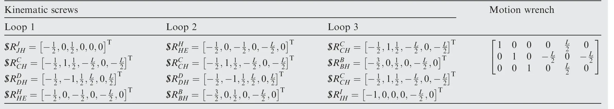
Table 14 Wrenches of the deployable structure shown in Fig.15.

Fig.16 Simulation results of the concurrent FFF deployable unit N8-R10.
5.Synthesis results with only one common constraint
Based on the former method,eleven planar folded rectangular PDTUs are synthesized.However,the conceptual design of rectangular PDTS with only one common overconstrained mechanism is difficult to determine by synthesizing;because of the characteristic differences between it and the eleven deployable units shown previously.Synthesis results of the rectangular PDTS with only one common overconstrained mechanism are listed in Table 15.
ADAMS is employed to verify the continuous folded and deployed motions of these overconstrained deployable units as shown from Figs.17 to 22.The simulation results indicate that the synthesis method proposed in this paper canobtain some deployable units with only one common constraint.

Fig.17 Single F Configuration.

Fig.18 Single C configuration.

Fig.19 Concurrent FF configuration.

Fig.20 Perpendicular FC configuration.

Fig.21 Spatial parallel FFF configuration.

Fig.22 Spatial concurrent FFF configuration.
6.Conclusions
(1)Rectangular pyramidal overconstrained deployable units are synthesized based on the screw principle.The necessary and sufficient conditions of continuous folded and deployed motions of the overconstrained deployable units are derived based on the virtual work principle.
(2)The configured principle of the kinematic joints of the PTDU is analyzed with twelve different common overconstrained mechanisms.
(3)The rectangular PDTUs with common and redundant constraints are systematically synthesized,and twentyeight kinds of overconstrained deployable units are obtained based on this configured principle of the kinematic joint.The simulation results of the new deployable units denote that all synthesized overconstrained deployable units can realize continuous folded and deployed motions under predetermined DOFs that are verified by ADAMS 2010.
Acknowledgements
This study was co-supported by the National Natural Science Foundation of China(No.51605001),in part by the Joint Funds of the National Natural Science Foundation of China(No.U1637207),Key Funds of the National Natural Science Foundation of China (No. 51835002), in part by Anhui University Research Foundation for Doctor of China(No.J01003222)and the Key Research and Development Plan of Anhui Province,China(201904A05020034).
 CHINESE JOURNAL OF AERONAUTICS2019年7期
- CHINESE JOURNAL OF AERONAUTICS的其它文章
- Guide for Authors
- Prediction of cutting forces in flank milling of parts with non-developable ruled surfaces
- A new error-controllable method for smoothing the G01 commands
- Electrochemical trepanning with uniform electrolyte flow around the entire blade profile
- Thermal-structure coupling analysis and multiobjective optimization of motor rotor in MSPMSM
- Lightweight structure of a phase-change thermal controller based on lattice cells manufactured by SLM