Upgrade to the front-end electronics of the BESIII muon identif i cation system
XI Jian-Bo(習(xí)建博),LIANG Hao(梁昊),,XIANG Shi-Tao(向石濤),GUO Di(郭迪),ZHOU Jin-Jin(周津津),LI Yu-Ying(李玉英),LI Yang(李揚(yáng)),LIU Han-Chao(劉漢超),ZHOU Yong-Zhao(周永釗),LI Chun-Hua(李春花),ZHANG Jia-Wen(張家文),CHEN Jin(陳進(jìn)),HE Kang-Lin(何康林),and ZHU Ke-Jun(朱科軍)
1State Key Laboratory of Particle Detection and Electronics(IHEP-USTC),Hefei 230026,China
2Department of Modern Physics,University of Science and Technology of China,Hefei 230026,China
3Institute of High Energy Physics,Chinese Academy of Sciences,Beijing 100049,China
Upgrade to the front-end electronics of the BESIII muon identif i cation system
XI Jian-Bo(習(xí)建博),1,2LIANG Hao(梁昊),1,2,?XIANG Shi-Tao(向石濤),1,2GUO Di(郭迪),1,2ZHOU Jin-Jin(周津津),1,2LI Yu-Ying(李玉英),1,2LI Yang(李揚(yáng)),1,2LIU Han-Chao(劉漢超),1,2ZHOU Yong-Zhao(周永釗),1,2LI Chun-Hua(李春花),3ZHANG Jia-Wen(張家文),3CHEN Jin(陳進(jìn)),3HE Kang-Lin(何康林),3and ZHU Ke-Jun(朱科軍)3
1State Key Laboratory of Particle Detection and Electronics(IHEP-USTC),Hefei 230026,China
2Department of Modern Physics,University of Science and Technology of China,Hefei 230026,China
3Institute of High Energy Physics,Chinese Academy of Sciences,Beijing 100049,China
Resistive Plate Chambers(RPCs)built from a new type of Bakelite developed at Institute of High Energy Physics(IHEP),Chinese Academy of Sciences have been used in the BESIII Muon identif i cation system for several years without linseed oil coating,but characteristic aging performances were observed.To adapt to the RPCs in the aging state,the front-end electronics have been upgraded by enhancing the front-end protection,improving the threshold setting circuit,and separating power supplies of the comparator and the f i eld programmable gate array(FPGA).Improvements in system stability,front-end protection and threshold consistency have been achieved.In this paper,the system upgrade and the test results are described in detail.
BESIII,Upgrade,Resistive Plate Chamber,Front-end protection
I.INTRODUCTION
Resistive Plate Chamber(RPC)is a gaseous detector widely used in many high energy physics experiments,such as the B-factory experiments(BaBar at SLAC and Belle at KEK),the LHC experiments(ALICE,ATLAS,CMS)and the ARGO cosmic ray experiment at Yangbajing in Tibet, China[1–9].The resistive material and surface smoothness of the resistive plate are critical for a good RPC.Differing from the glass electrodes in Belle or the bakelite plates with linseed oil treatment in BaBar,the resistive material of electrodes used in the RPC for the muon identif i cation system of Beijing Spectrometer(BESIII)is a special type of phenolic laminate[10].Surface quality of these laminates is superior to other bakelite plates used to construct RPCs elsewhere.However,like other gaseous detectors,the BESIII-type RPCs working in streamer mode also suffer from aging problems[11].The aging effect causes declining eff i ciency of the detectors and failure of the electronics.Thus,it is necessary to upgrade the electronics to achieve high stability and reliability needed for the BESIII muon identif i cation system.
In this paper,we report our work on upgrading to the frontend electronics of the BESIII muon identif i cation system,focusing on the possibility of using two stages of the back-toback protection diode(BBPD)for the streamer mode working RPCs,and on the method of how to improve the threshold consistency.Afterinstallationoftheupgradedelectronics,the test results show that the goals of higher stability and reliable front-end protection are achieved,and the threshold consistency is improved as expected.
II.UPGRADES TO THE RPC ELECTRONIC SYSTEM
A.Enhancing the front-end protection
The original FECs is of one stage of BBPD with a 20?resistor to prevent possible sparks from RPCs,but this onestage design fails to protect the circuit effectively.Sometimes,the strips of RPCs generate abnormally large signals at the moment of beam loss because of the high sensitivity of the RPC detectors.In presence of these large input signals, the output after one stage of BBPD remained high enough to damage the comparator.To provide better protection,the one stage of BBPD was upgraded to two stages of BBPD[12],as shown in Fig.1.The two stages of BBPD were expected to reduce the abnormally large signal amplitude to a safe level without affecting normal small signals or the eff i ciency of the RPC detector.This circuit was simulated using PSpice.A schematic of this simulation is shown in Fig.2.

Fig.1.Front-end protection circuit with two BBPD stages.
Table 1 shows the results of a simulation of one and two stages of BBPD with small input signals and large input signals,which are both likely to appear in the real RPC output. The results show that,for large input signals,the output am-plitudes after one stage of BBTD are 30V and?29V,being stillhighenoughtodamagethecomparator.Thetwostagesof BBPD,with the outputs of 2V and?2V,are capable of protectingthecomparatorfromlargesignals.Forsmallinputsignals,the diode junction capacitance is somewhat small(about 2pF for a diode in MA3J147 used in BBTD),so the two stages of BBDP show only little more attenuation than one BBDP stage,which does not affect the eff i ciency of the RPC detector signif i cantly.These results of the simulation indicate that two stages of BBDP can be used in the FECs.

TABLE 1.Simulation results
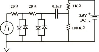
Fig.2.(Color online)Simulation scheme.
B.Improving the threshold setting circuit
Both the high RPC voltage and FEC threshold contributed to the RPC eff i ciency.We lower the high voltage to avoid RPC and FEC failure,and lower the FEC threshold to maintain the RPC eff i ciency.In this way,the FEC threshold was expected to have a low relative error,especially at low thresholds.This would guarantee the consistency of the threshold for all the 572 FECs used in the BESIII.
The original FEC threshold setting circuit is shown in Fig.3(a).It consists of a DAC,an emitter follower,and a comparator.As the input signal of comparator is pulled up toVDC,the corresponding threshold can be calculated as:

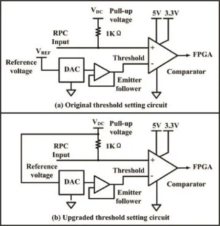
Fig.3.Threshold setting circuit.
where,VDCis comparator pull-up voltage(2.5V),VDACis the DAC output voltage,Dis the DAC setting code,andVREFis the DAC reference voltage(2.5V).The original FECs used a voltage regulator for the pull-up voltage and another regulator diode for the DAC reference voltage.Considering the integral nonlinearity(INL)oftheDACandaccuracyofeachregulator, the worst absolute error of the corresponding threshold can be calculated by Eq.2,

The INL of the DAC is±1/2 LSB and the accuracy of each regulator is 1%.The absolute error of the corresponding threshold as a function of DAC code is shown in Fig.4.When the threshold is set to a low value,such as 48.8mV(DAC code 251),the absolute error is 35.1mV and the relative error is 72%,which are apparently unbearable.
The problem is solved by using a single regulator for both comparator pull-up and DAC reference voltage[13].In the upgraded threshold setting circuit,shown in Fig.3(b),the threshold can be calculated by Eq.3,
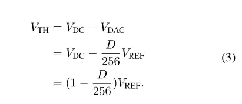
The worst absolute error of the threshold can be calculated as:

In this case,the absolute error of threshold will be significantly reduced,especially when the threshold is set at a low range,as shown in Fig.4.Take a threshold of 48.8mV(DAC code 251)as an example,the worst absolute error in the upgraded threshold setting circuit drops to only 4.9mV.The thresholds between different FECs vary by no more than the worst absolute error of threshold.Threshold consistency was signif i cantly improved after the upgrade.
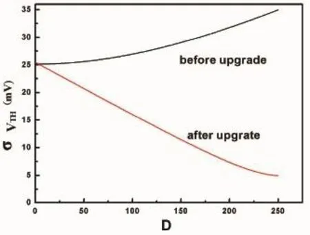
Fig.4.Absolute error of threshold vs.DAC code.
C.Separating power supplies of comparator and FPGA
The data transmission for the RPC front-end readout electronics system is organized in the form of daisy chain,in which the FPGA plays a key role.In the original design of the FECs,due to the regulator supplies 3.3V voltage both to the comparator and FPGA,once the comparator was damaged,the FPGA couldn’t work either,causing the entire data chain to crash.As a precautionary measure to ensure data from other FECs transmitted properly on occurrence of any FEC comparator failure,the comparator and the FPGA were upgraded to use separate powers.
III.TESTS AND INSTALLATION
A.Test of front-end protection
The front-end protection circuit was tested to determine whether the two stages of diodes were suitable for the upgrade[14].To assess the protection for large signals,input signals of 710V and?690V amplitudes were fed as input into the two BBDP stages,as shown in Fig.5(Ch1).The output signals of the two stages showed amplitudes of 2.2V and?3.2V,respectively,shown in Fig.5(Ch2).The comparator exhibited no failure for such large input pulses.Concerning small signals,two pulses with amplitudes of?58mV and?100mV served as input to the double BBDP stage,as shown in Fig.6(Ch1).The observed pulse amplitudes at the output of the protection circuit were?54mV and?95mV, respectively,also shown in Fig.6(Ch2).The values were consistent with our simulation,giving the desired attenuation for large signals while minimally attenuating small ones.The results indicated that the upgrade of the front-end protection was effective and appropriate.
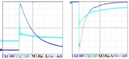
Fig.5.(Color online)Waveforms for large input signals.
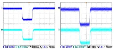
Fig.6.(Color online)Waveforms for small input signals.
B.Test of FEC threshold consistency
This test involved a random selection of 15 FECs from 700 candidate FECs and analysis of the variation in thresholds between different FECs with the DAC codes set at 252,251 and 250[15].The corresponding threshold value was recorded by measuring the actual threshold value compared to the comparator pull-up voltage on each board.The results are givenin Table 2.One sees that the difference between these FEC thresholds is about 1%after the upgrade.

TABLE 2.Upgraded FECs threshold consistency test
C.The RPC cosmic ray test
Figure 7 shows the histograms of a cosmic ray test using(a)the original FECs and(b)the upgraded FECs[16], at the same high-voltage(7.7kV)and threshold(50mV)settings.For the original FECs,some channels have unexpectedly more counts,and it appears that the thresholds of these channels were comparatively lower than others.For the upgraded FECs,there are counts in each of the channels but no channels have excessively large counts.This indicates that the threshold consistency is surely improved after the upgrade.
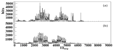
Fig.7.The histograms of a cosmic ray test.
D.Eff i ciency and noise test
Tests of eff i ciency and noise for the RPCs detectors were conducted under the cosmic ray environment after the upgraded FECs installed in the BESIII.As a function of voltage,Fig.8 shows the eff i ciency and Fig.9 shows the noise, for three threshold settings at 40mV,50mV,and 60mV. The 7.7kV eff i ciency of the RPC reached 95–96%at 50mV threshold while the noise was about 0.08Hz/cm2.The results are up to the system indicators,which conf i rm the upgrade is successful.
IV.INSTALLATION OF UPGRADED FECS
A total of 572 FECs were installed at BESIII in 2011.Because of diff i culties in the maintenance of the endcaps,extension cables were used for the FECs in the shielded box adjacent to the spectrometer.This is shown in Fig.10.
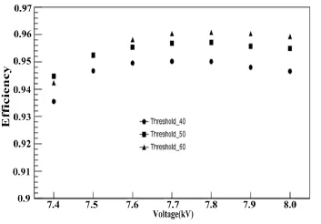
Fig.8.Eff i ciency test results.
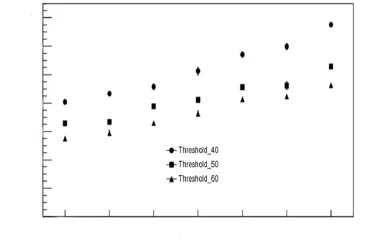
Fig.9.Noise test results.
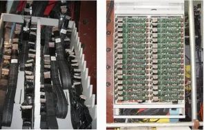
Fig.10.(Color online)Extension cables and the shielded box.
V.CONCLUSION
The RPC FECs were upgraded to produce the high stability and reliability needed for the BESIII muon spectrometer. First,two stages of BBPD were added before the comparatorto prevent FECs from being damaged by the large signals that occur when the RPC sparks.Second,the comparator pull-up and DAC reference voltage were supplied with a single voltage regulator to improve the threshold consistency.At last, the power supplies of the comparator and FPGA were separated to ensure that FPGA continue to work normally even if the comparator was damaged.The upgraded FECs have been constructed and tested.A total of 572 FECs were installed on the BESIII during the summer of 2011.A week-long cosmic ray test has been conducted and the result shows that the upgraded RPC readout electronics meet the requirements of the BESIII.
[1]BaBar.Technical Design Report,SLAC-R-457,March 1995.
[2]Aubert B,Bazan A,Boucham A,et al.Nucl Instrum Meth A, 2002,479:1–116.
[3]BELLE Collaboration,A study of CP violation in B meson decays,Technical Design Report,KEK Report 95-1,April 1995.
[4]Abashian A,Gotow K,Morgan N,et al.Nucl Instrum Meth A, 2002,479:117–232.
[5]ALICE Collaboration,TDR of the Muon Spectrometer, CERN/LHCC 1999,99–22.
[6]Spegel M.Nucl Instrum Meth A,2000,453:308–314.
[7]ATLAS Muon Collaboration,ATLAS Muon Technical Design Report,CERN/LHCC1997,97–22.
[8]CMS Collaboration,Muon Project,CERN/LHCC 97-32,1997.
[9]Aielli G,Assiro R,Bacci C,et al.Nucl Instrum Meth A,2006,562:92–96.
[10]Zhang J,Qian S,Chen J,et al.Nucl Instrum Meth A,2010,614:195–205.
[11]Lu C,McDonald K,Smith A,et al.Nucl Instrum Meth A, 2012,661:226–229.
[12]Arai Y,Ball B,Beretta M,et al.J Instrum,2008,3:09001.
[13]Hao H,Liang H,Zheng L,et al.Nucl Sci Tech,2013,24: 010401.
[14]Aielli G,Camarri P,Cardarelli R,et al.Nucl Instrum Meth A, 2003,508:189–189.
[15]Yang H,Liang H,Yuan Y,et al.IEEE T Nucl Sci,2010,57: 2371–2371.
[16]Dou F,Liang H,Zhou L,et al.Nucl Sci Tech,2012,23:284–288.
10.13538/j.1001-8042/nst.25.020402
(Received May 29,2013;accepted in revised form November 8,2013;published online April 20,2014)
?Corresponding author,simonlh@ustc.edu.cn
——石濤研究三著
 Nuclear Science and Techniques2014年2期
- Nuclear Science and Techniques的其它文章
- A hybrid voxel sampling method for constructing Rad-HUMAN phantom?
- Measurement of keffwith an improved neutron source multiplication method based on numerical analysis?
- Simulation of neutron diffusion and transient analysis of MSR?
- Ordered water monolayer on ionic model substrates studied by molecular dynamics simulations?
- A method for determination of the s orbital component of12Be ground state?
- Demonstration of Pm-147 GaN betavoltaic cells
