
MOTION OF TRACER PARTICLES IN A CENTRIFUGAL PUMP AND ITS TRACKING CHARACTERISTICS*
2012-08-22 08:31:57LIYalinYUANShouqiTANGYueYUANJianping
水動(dòng)力學(xué)研究與進(jìn)展 B輯 2012年5期
LI Ya-lin, YUAN Shou-qi, TANG Yue, YUAN Jian-ping
Research Center of Fluid Machinery Engineering and Technology, Jiangsu University, Zhenjiang 212013, China, E-mail: yuanfangfriend@126.com
(Received December 14, 2011, Revised July 10, 2012)
MOTION OF TRACER PARTICLES IN A CENTRIFUGAL PUMP AND ITS TRACKING CHARACTERISTICS*
LI Ya-lin, YUAN Shou-qi, TANG Yue, YUAN Jian-ping
Research Center of Fluid Machinery Engineering and Technology, Jiangsu University, Zhenjiang 212013, China, E-mail: yuanfangfriend@126.com
(Received December 14, 2011, Revised July 10, 2012)
The Basset-Boussinesq-Oseen (BBO) equation can be used for most flows to trace the motion of a particle, but in a centrifugal pump, among the forces that act on the particles, one should also include those due to the impeller rotation, as additional effects. This paper firstly reviews various approximations of the BBO equation for the motion of dispersion particles in a viscous fluid. Then based on the motion equation for particles in low Reynolds number centrifugal pumps, a formula for calculating the tracking characteristics of tracer particles is deduced through the Fourier integral transformation. After that the deviations of the particle motion from the fluid motion, as predicted by the various approximations, are discussed and compared. At last, with an emphasis on the Particle Image Velocimetry (PIV) results, the tracking characteristics of particles are estimated. Also, advantages and disadvantages of different tracer particles are discussed and suitable tracer particles for application in PIV studies for flow fields in centrifugal pumps are suggested.
tracer particles, equations of motion, tracking characteristics, centrifugal pump, Particle Image Velocimetry (PIV)
Introduction
In contrast to the hot-wire or the laser Doppler anemometry, the Particle Image Velocimetry (PIV) can offer many advantages in the study of centrifugal pumps[1-6]. The PIV measurement technique is an indirect method, as it determines the particle velocity instead of the fluid velocity. Therefore, the fluid mechanical properties of the particles have to be examined in order to avoid significant discrepancies between fluid and particle motions, as known as PIV errors[7,8]. For the selection of tracer particles, two aspects must be considered: how well the particles can follow the flow and how fast they can respond to the velocity changes in the flow field.
The statistical properties of seeding particle tracking characteristics are described by the Basset-Boussinesq-Oseen (BBO) equation in consideration ofthe motion of the particle as a sphere in a moving flow field. The most notable approximations can be classified into four classes[9], as will be discussed in the following section, and the similar studies are also found in Zhang et al.[10,11], Liang and Zhao[12], Yan et al.[13], Li et al.[14]and others. It is recognized that the BBO equation is adequate for most flows. But in some cases, the BBO equation has to be corrected and improved. One such case is the shear flow, where a transverse lift force is exerted on a suspended particle. In a swirling flow, the centrifugal force explicitly neglected in the BBO equation is important, which would accelerate the particle in the radial direction out of the vortex core. In the hydrocyclone flow fields, the centrifugal force generated by the curved wall would seriously affect the tracking behaviors of particles in the radial direction. So the particle motion equation should be based on the force analysis in the flow fields. For the dynamics of the solid particles in the liquid flow of centrifugal pumps, the forces considered in the BBO equation are not enough. They should include not only the centrifugal force and the Coriolis force caused by the impeller rotation, but also the centrifugal force caused by the curved wall[15]. The forces on the particles in the centrifugal pump are, therefore,very complex. The tracking capability of the seeding particles in the centrifugal pump used to be studied by a simplified BBO equation without a comprehensive force analysis[13].
Various motion equations of a particle are first reviewed and formulas for calculating the tracking behaviors of tracer particles in a centrifugal pump are then deduced, respectively, in the circumferential and radial directions. The tracking capabilities of seeding particles are finally estimated to provide a guidance for selecting suitable tracer particles for the PIV test in a centrifugal pump.
1. Particle dynamics
1.1 Various equations of motion in a turbulent fluid
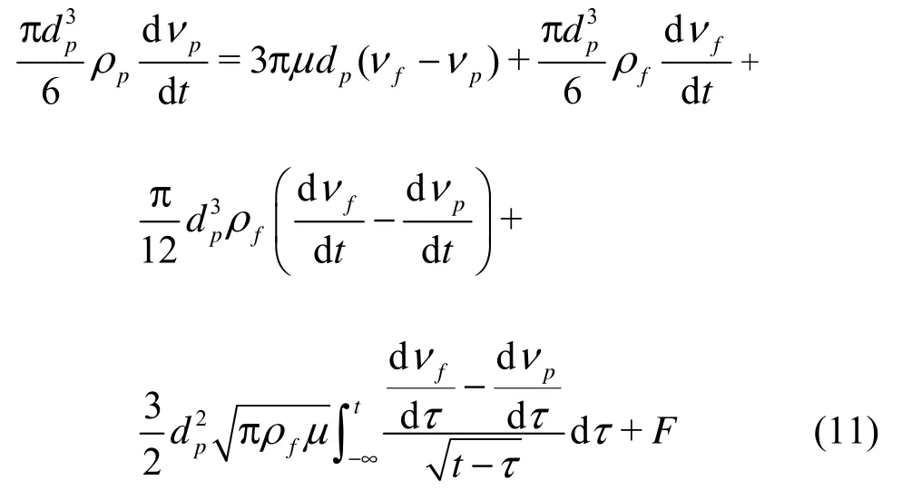
A one-dimensional equation describing the movement of a spherical particle with diameter ofpd and density ofpρ in a fluid with densityfρ, dynamic viscosity μ and velocityfv can be described by the BBO Equation proposed by Basset in 1888.
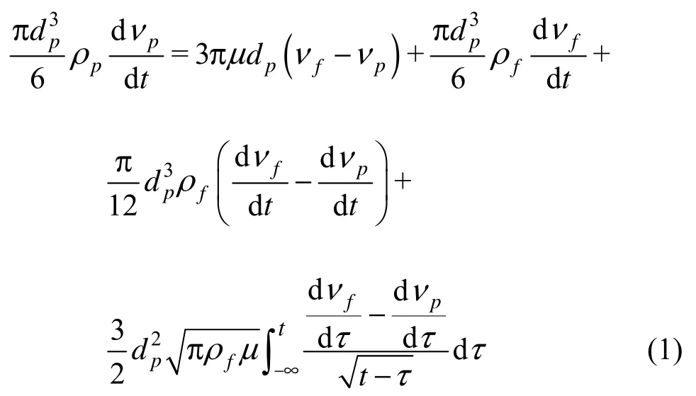
wherepv is the velocity of particles. The first term on the right side is the steady state drag force, the second term is the pressure gradient force, the third term is the added mass force and the last term is the Basset history integral.
To simplify the form, Eq.(1) is written as
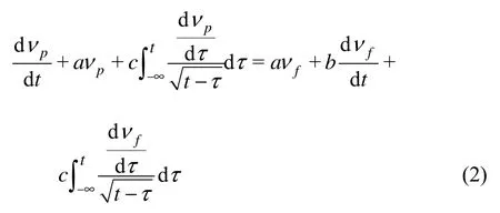
in which
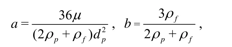
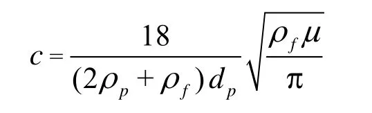
This is used as the general equation of motion.
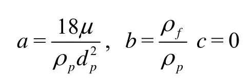
If neglecting only the history term, Eq.(2) can be solved to obtain the solution of Hinze and Liu[9].
This is called a Type I approximation.
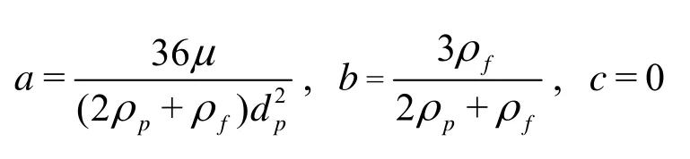
If neglecting the history and add mass terms, Eq.(2) can be solved to obtain the solution of Friedlander[9]
This is called a Type II approximation.
If neglecting the pressure gradient effect as well as the added mass and history, Eq.(2) can be solved to obtain the solution of Soo[9].
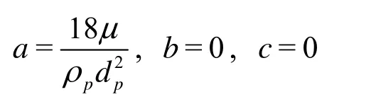
This is called a Type III approximation.
The turbulent velocityfv can be seen as the superposition of a series of different frequency signals, which can be expressed in their Fourier integrals[12,14]
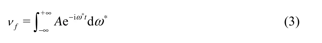
where A denotes the complex amplitude, as a function of ω*, while ω*is the angular frequency of the turbulent motion.
The amplitude ratio and the phase angle are used to express the particle velocity in terms of the fluid velocity. The particles velocitypv can, therefore, be expressed as
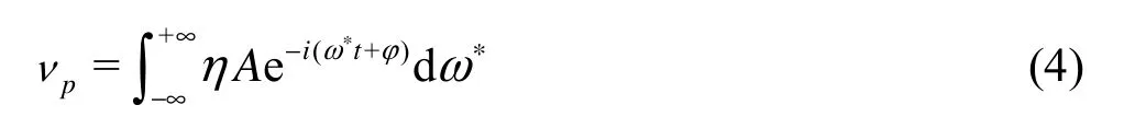
where η is the amplitude radio of the particle and the fluid velocities, and φ is the phase lag of the particle motion, which are functions of the angular frequency of the turbulent motion ω*. Thus, the various approximations of particle tracking characteristics can be studied by comparing the respective amplitude ratios and phase angles.
Taking derivatives of Eqs.(3) and (4), one obtains
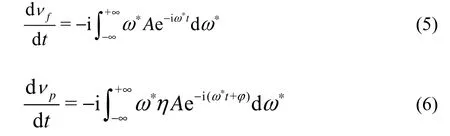
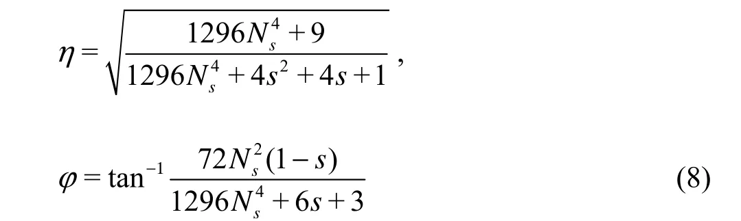
Substitution of the relations into Eq.(2) yields
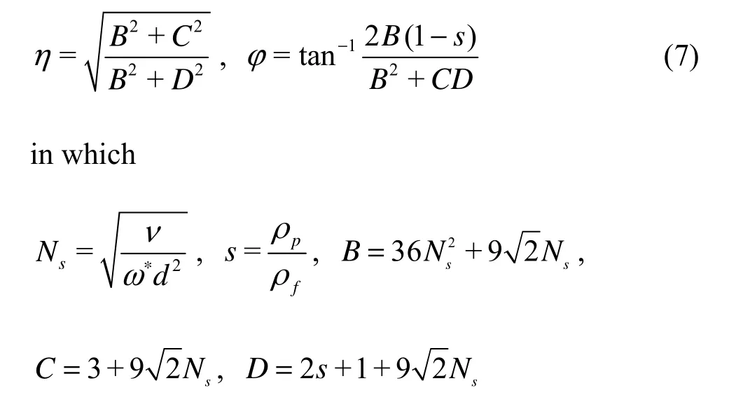
Nsis called the Stokes number, s is called the density ratio.
With the same method, for the Type I approximation
for the Type II approximation
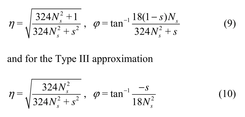
These are four classes of approximations for the motion of a particle in a viscous fluid.
1.2 Equations of motion in the centrifugal pump
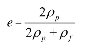
Although various approximations of the BBO equation for the motion of a particle in a viscous fluid were widely applied to the complex phenomenon of the dispersion in most turbulent fluids, we should include , the centrifugal force Fr(which is called the first kind of centrifugal forces) and the Coriolis force Fccaused by the impeller rotation, the centrifugal forceFR(which is called the second kind of centrifugal forces) caused by the curved wall and gravity Fgand the buoyancy Ffinto the forces acted on particles for its application in a centrifugal pump. These forces are shown in Fig.1, which are called jointly as the external potential force[15]. F
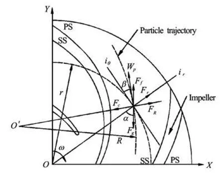
Fig.1 Model of the external potential force on the tracer particles
So the Lagrange equation of the particle motion in the centrifugal pump is
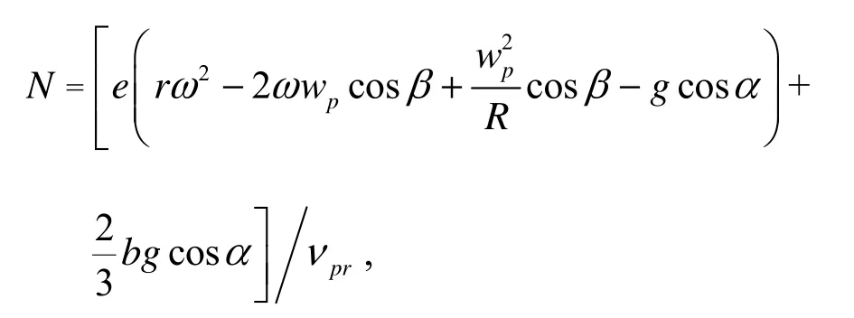
Using the same mathematical approach as that for the hydrocyclone, Eq.(11) is applied to the tracer particles in the flow field of a centrifugal pump at different directions. Except the term of potential forces, all other terms take the same form in different directions. The potential forces Fiθ(iθdenotes the circumfe- rential direction of the centrifugal impeller, as shown in Fig.1) can be expressed as
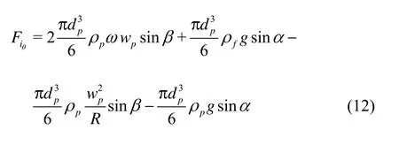
where ω is the impeller angular velocity,wpis the relative velocity of tracer particles, R is the radius of FR, α is the angle between gravity andiθdirection,β is the relatively liquid flow angle.
Substituting Eq.(12) into Eq.(11), we have
in which
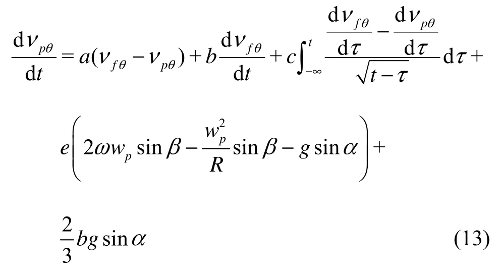
Substituting Eqs.(3)-(6) into Eq.(13), we have
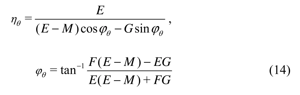
in which
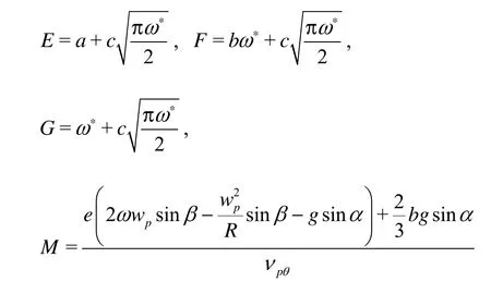
This is called a circumferential type approximation for centrifugal pumps. With the same method, a radial type approximation can also be obtained as
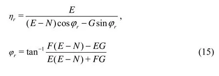
in which
r is the radius ofFr.
To obtain the velocity fields of particles by the PIV, the tracking accuracy of seeding particles can be estimated by using Eqs.(14) through (15) , which are the formulas of tracking characteristics in the centrifugal pump.
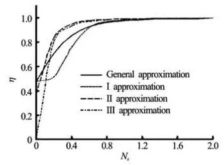
Fig.2 Amplitude ratio calculated by four types ofapproximations
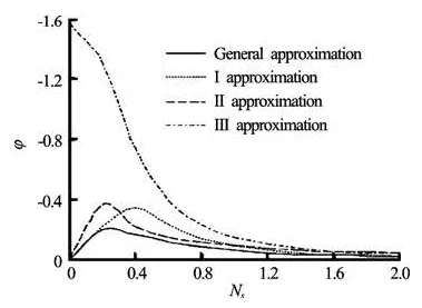
Fig.3 Phase angle diagram calculated by four types of approximations
2. Comparis on among various approximations
Figures 2 and 3 show the amplitude ratios and the phase angles for various Stokes numbers and forthe density ratio of 2.70 computed by four types of approximations. All solutions indicate that the effect of neglecting some terms is significant at higher frequencies. Each term has its own role, so neglecting one term may produce a large error in some conditions. From these curves, it is possible to determine the range of frequencies in which the deviation of the theories becomes negligible and the conditions for which theparticle follows the fluid[9]. For centrifugal pumps, these curves are obviously not applicable because of external potential forces in the centrifugal impellers. This is the main reason why we establish the equations of motion of a particle in the flow field of centrifugal pumps in the Section 1.2.
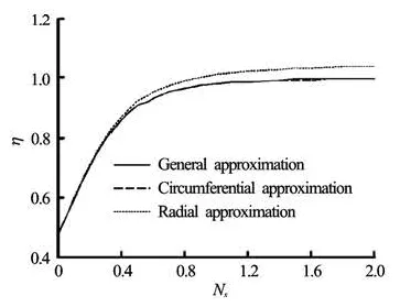
Fig.4 Am plitude ratio for discrete particles in a turbulentfield of centrifugal pump
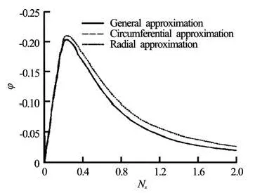
Fig.5 Phase angle diagram for discrete particles in a turbulent field of centrifugal pump
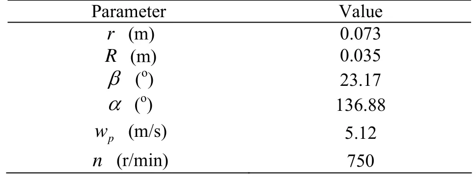
Table 1 comparison of tracer particles
Figures4 to 5 show the amplitude ratiosand the phase angles for various Stokes numbers and for density ratio of 2.70 computed by General, Circumferential and Radial approximations. From Eqs.(14) through (15), the calculation parameters selected are shown in Table 1.
From Figs.4 and 5, it is seen that the approximations between the general type and the circumferential type give nearly the same solutions. At low frequencies, however, the radial type is different from the general type but with a same trend. So the general type would involve a larger error at lower frequencies in the radial direction.
The agreement in the circumferential direction is better than that in the radial direction. In the circumferential direction, the gravity and the buoyancy may offset each other. For backswept blades, the Coriolis force Fccaused by the impeller rotation and the second kind of centrifugal forces FRcaused by the curved wall are in the opposite direction, and may also offset each other to some extent. So the deviation between the general and circumferential approximations is small. While in the radial direction, there is an additional force which is called the first kind of centrifugal forces Frcaused by the impeller rotation. The force Frmakes the radial approximation different from the general approximation, especially, at lower frequencies.
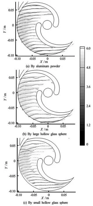
Fig .6 Phase-averaged vector maps of the relative velocitydistribution
3. Applications in the centrifugal pump
In using the average method to deal with the images taken by the PIV, the velocity of both the particles and the fluid can be seen as constant independent of time, so the turbulent frequency ω*can be considered as zero. With ω*=0 in Eqs.(14) and (15), we have:
At the circumferential direction
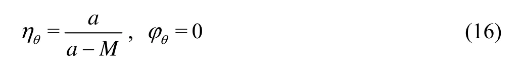
At the radial dir ection
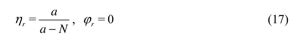
From Eqs.(16) and(17), it is not difficult to see that the phase angle of the particles is equal to that of the fluid, but the amplitude ratio is different. In dealing with the phase average processing, the effects of the fluid turbulent fluctuation will not be reflected on the particles. This model deals with the dispersion of the tracer particles by assuming that the flow field of the centrifugal pump is steady. Then the deviations of the particle motion from the fluid motion as predicted by Eqs.(16) and (17) are considered.
Figure 6 shows the relative velocity fields, separately, for the three kinds of particles by the PIV under the same experimental conditions. The tracer particles used are the aluminum powders with density of 3.9 kg/m3to 4.0×10³kg/m3and diameter of 3 μm, the large hollow glass spheres with density of 1.05× 10³kg/m3and diameter of 20 μm to 60 μm and the small hollow glass spheres with density of 1.05× 10³kg/m3and diameter of 1 μm to 5 μm.
From Fig.6, the magnitudes and the directions of velocities vary differently for the three kinds of particles due to their different tracking characteristics. It is possible to determine the conditions for which the particle follows the fluid in the centrifugal pump. Figure 6 provides the unknown parameters required by Eqs.(16) and (17), so the tracking characteristics of all particles can be estimated by calculating the amplitude ratios.
The results for the three kinds of seeding particles are computed and shown in Figs.7 through 9. The tracking capabilities of each kind of tracer particles are calculated with its maximum diameter of2/rR= 0.50, 0.70 and 0.90, in which θ*is the normalized circumferential coordinate, θ*=0 and θ*=1represent the circumferential positions on the impeller suction side (ss) and on the pressure side (ps), respectively.
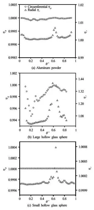
Fig.7 Estimations the amplitude ratios of tracer particlesof r/R2=0.50
As seen fromFigs.7 through 9, the best tracking characteristics are obtained with small hollow glass spheres, followed by those with aluminum powders, and finally those with large hollow glass spheres. The main reason of these results is that the diameters of the aluminum powders and the small hollow glass spheres are much smaller than that of the large hollow glass spheres which is about an order of magnitude larger.
It can also be seen that the radial tracking feature is worsethan the circumferential one, because of the firstkind of centrifugal force only acting on the radial position. According to the formula of the centrifugal force, the magnitude of the centrifugal force is proportional to its mass. Taking the hollow glass sphereswith a size of 60 μm and the aluminum powders with a size of 3 μm as examples, the mass of the former is about 2 000 times that of the latter, so the hollow glass spheres will be acted by a larger centrifugal force at the same location, which makes the tracking behaviors for the radial position much worse.
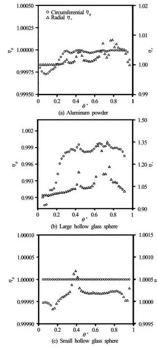
Fig.8 Estimations the amplitude ratios of tracer particlesof r/R2=0.70
The limited amplitude ratio (0.9<η<1.1)is taken as the indexes of the good tracking behaviors of tracer particles in the flow fields of centrifugal pumps, and the tracking accuracy of three particles basically can meet the requirement except for some points in the radial position in the case of large hollow glass spheres. For large hollow glass spheres with size in the range from 20 μm to 60 μm, an estimation of tracking behaviors is made for the maximum diameter of 60 μm, therefore, the actual tracking accuracy for large hollow glass spheres is better than the estimation. If the diameter used for the calculation is 20 μm, the tracking accuracy of large hollow glass sphere is also very high, as shown in Fig.10, in which only a few points are found with amplitude ratio exceeding 1.1 for the radius of 0.05 m.
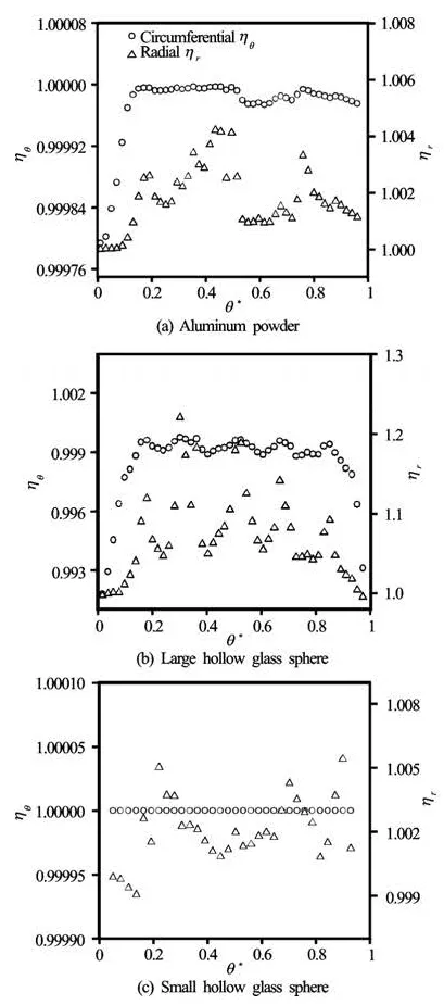
Fig.9 Estimations the amplitude ratios of tracer particlesof r/R2=0.90
4. Seeding particles for the centrifugal pump
By the above calculation and analysis of test results, the optimal choice among the three tracerparticlesis shown in Table 2, where the tracking characteristics of the tracer particles are evaluated by Eq.(18). Another important characteristic of the tracer particles is the scattering, which is shown in Fig.11.
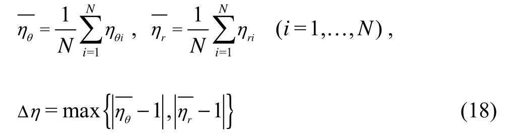
where Δηrepresents the deviations of the particle motion from the fluid motion, N is the sum of hits from measurement results for r/R2=0.50, 0.70 and 0.90.
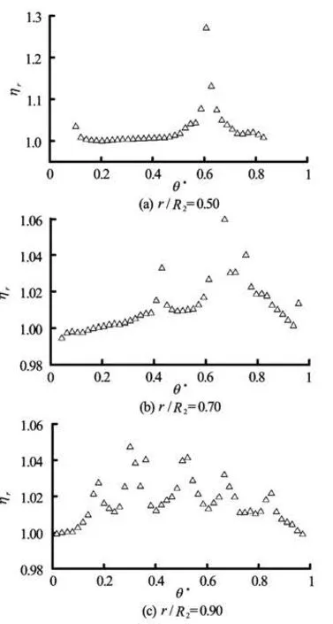
Fig.10Estimations the amplitude ratios of large hollow glass sphere with diameter of 20 μm at radial position
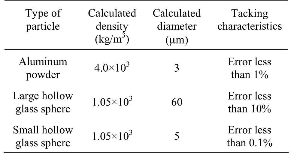
Table 2 Comparison of the tracking characteristics
Table 2 shows that the tracking characteristics of small hollow glass spheres are the best among the threekinds of particles. But its scattering characteristics are the worst (as shown in Fig.11), which can also affect the accuracy of experimental measurements. Both the tracking and the scattering characteristics of aluminum powders can meet the requirements of the PIV test except for its settlement. The aluminum powder particles are not neutral suspension particles because of their high densities, so a great number of aluminum powders deposit on the bottom of the storage tank. It is necessary to do a mixing for the water in the tank to keep the particle concentration during the experiment. Large hollow glass spheres are most suitable for this experiment, though their maximum diameter of 60 μm will affect the tracking behaviors. If the diameter of large hollow glass spheres is only 20 μm, not only the precision of tracking characteristics will be very high, but also its scattering characteristics can meet the requirements of the experiment. Through the above analysis, it is proposed that the neutral suspension particles of 20 μm in diameter should be used as tracer particles for the PIV studies of the flow field in this centrifugal pump.
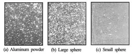
Fig.11 Scattering of solid particles
5. Conclusions
In the present paper, the formula for calculating the tracking behaviors of tracer particles in the centrifugal pump is deduced and the results of the PIV by using three kinds of tracer particles are analyzed. The main conclusions are as follows:
(1) With the consideration of the characteristics of the impeller rotation, the potential forces are added to the BBO equation, and the formula for calculating the tracking behaviors of tracer particles in the centrifugal pump is deduced through the Fourier integral transformation. Some difference between the radial and circumferential tracking behaviors is found as from Eqs.(14) and (15). As the first kind of centrifugal force acts only on the radial position, the radial tracking feature is worse than the circumferential one from the estimation of the experimental results.
(2) Comparing various approximations applied for the motion of a particle, it is found that neglecting someterms may produce a large error in a certain range of frequencies. If neglecting the terms caused by the impeller rotation, a large discrepancies between the general approach and the radial approach would be found in the low range of frequencies for centrifugal pumps.
(3) Analyzing the test results for the characteristics ofthe tracer particles, it is found that the scatteringcharacteristics of small hollow glass spheres are not satisfactory and aluminum powders are easy to settle, therefore, large hollow glass spheres are appropriate as tracer particles for centrifugal pumps in the PIV studies. Through estimating the tracking characteristics of particles and considering the light scattering characteristics of particles, this pump should use hollow glass spheres ( or other neutral suspension particles ) of 20 μm in diameter as tracer particles.
[1] PEDERSEN N., LARSEN P. S. and JACOBSEN C. B. Flow in a centrifugal pump impeller at design and off design conditions part I: Particle Image Velocimetry (PIV) and Laser Doppler Velocimetry (LDV) measurements[J]. Journal of Fluids Engineering, 2003, 125(1): 61-72.
[2]ADRIAN R. J. Twenty years of particle image veloci- metry[J]. Experiments in fluids, 2005, 39(2): 159-169.
[3] CHOI Y., KUROKAWA J. and MATSUI J. Performance and internal flow characteristics of a very low specific speed centrifugal pump[J]. Journal of Fluids Engineering, 2006, 128(2): 341-349.
[4]FENG J., BENRA F.- K. and DOHMEN H. J. Unsteady flow visualization at part-load conditions of a radial diffuser pump: By PIV and CFD[J]. Journal of Visualization, 2009, 12(1): 65-72.
[5]FAN Hui-min, HONG Fang-wen and ZHANG Guoping et al. Applications of CFD Technique in the design and flow analysis of implantable axial flow blood pump[J]. Journal of Hydrodynamics, 2010, 22(4): 518-525.
[6] SHAO Chun-lei, GU Bo-qin and HUANG Xing-lu et al. Experimental study on flow in the impeller of low specific speed pump using particle image velocimetry[J]. Journal of Aerospace Power, 2010, 25(9): 2091-2096(in Chinese).
[7]HART D. P. PIV error correction[J]. Experiments in Fluids, 2000, 29(1): 13-22.
[8] RAGNI D., SCHRIJER F. and Van OUDHEUSDEN B. W. Particle tracer responseacross shocks measured by PIV[J]. Experiments in fluids, 2011, 50(1): 53-64.
[9]HJELMFELT A. T., MOCKROS L. F. Motion of discrete particles in a turbulent fluid[J]. Applied Scientific Research, 1966, 16(1): 149-161.
[10]ZHANG T., CELIK D. and Van SCIVER S. W. Tracer particles for application to PIV studies of liquid helium[J]. Journal of Low Temperature Physics, 2004, 134(3-4): 985-1000.
[11]ZHANG T., Van SCIVER S. W. The motion of micronsized particles in He II counterflow as observed by the PIV technique[J]. Journal of Low Temperature Phy- sics, 2005, 138(3-4): 865-870.
[12] LIANG Gui-hua, ZHAO Yu. Analyses of following behaviors as tracer particle by PIV in chamber of internal combustion engine[J]. Journal of Dalian University of Technology, 2004, 44(5): 662-665(in Chinese).
[13]YAN Jing, YANG Xiao-lin and DENG Wan-quan et al. Analysis on following features of tracer particles[J]. Transactions of the Chinese Society for Agricultural Machinery, 2005, 36(6): 54-56(in Chinese).
[14] LI En-bang, LI Zhi-ping and LI Chun et al. Numerical analysis of following behaviors of particle tracers in turlent[J]. Chinese Journal of Scientific Instrument, 2009, 30(2): 225-231(in Chinese).
[15] LI Ya-lin, YUAN Shou-qi and TANG Yue et al. Analysis on tracing ability of PIV seeding particles in flow fields of centrifugal pumps[J]. Journal of Drainage and Irrigation Machinery Engineering, 2012, 30(1): 6-10(in Chinese).
10.1016/S1001-6058(11)60304-1
* Project supported by the National Outstanding Young Scientist Funds of China (Grant No. 50825902), the Jiangsu Provincial Innovative Scholars “Climbing” Project of China (Grant No. BK2009006) and the National Natural Science Foundation of China (Grant No. 50979034).
Biography: LI Ya-lin (1984- ), Male, Ph. D.
 水動(dòng)力學(xué)研究與進(jìn)展 B輯2012年5期
- 水動(dòng)力學(xué)研究與進(jìn)展 B輯的其它文章
- EFFECT OF SWEEP AND EJECTION EVENTS ON PARTICLE DISPERSION IN WALL BOUNDED TURBULENT FLOWS*
- EXPERIMENTAL STUDY HYDRAULIC ROUGHNESS FOR KAN TIN MAIN DRAINAGE CHANNEI IN HONG KONG*
- NUMERICAL STUDY OF FLOW AROUND AN OSCILLATING DIAMOND PRISM AND CIRCULAR CYLINDER AT LOW KEULEGAN-CARPENTER NUMBER*
- EFFECTS OF LIQUID COMPRESSIBILITY ON RADIAL OSCILLATIONS OF GAS BUBBLES IN LIQUIDS*
- SUPERCAVITY MOTION WITH INERTIAL FORCE IN THE VERTICAL PLANE*
- PARAMETRIC IDENTIFICATION AND SENSITIVITY ANALYSIS FOR AUTONOMOUS UNDERWATER VEHICLES IN DIVING PLANE*