
NUMERICAL STUDY OF FLOW AROUND AN OSCILLATING DIAMOND PRISM AND CIRCULAR CYLINDER AT LOW KEULEGAN-CARPENTER NUMBER*
2012-08-22 08:31:57GHOZLANIBelgacemHAFSIAZouhaierMAALELKhlifa
水動力學(xué)研究與進(jìn)展 B輯 2012年5期
GHOZLANI Belgacem, HAFSIA Zouhaier, MAALEL Khlifa
Ecole Nationale d’Ingénieurs de Tunis, Laboratoire de Modélisation en’Hydraulique et Environnement, B.P. 37. Le Belvédère, 1002 Tunis, Tunisia, E-mail: ghozlanib@yahoo.fr
(Received October 29, 2011, Revised April 23, 2012)
NUMERICAL STUDY OF FLOW AROUND AN OSCILLATING DIAMOND PRISM AND CIRCULAR CYLINDER AT LOW KEULEGAN-CARPENTER NUMBER*
GHOZLANI Belgacem, HAFSIA Zouhaier, MAALEL Khlifa
Ecole Nationale d’Ingénieurs de Tunis, Laboratoire de Modélisation en’Hydraulique et Environnement, B.P. 37. Le Belvédère, 1002 Tunis, Tunisia, E-mail: ghozlanib@yahoo.fr
(Received October 29, 2011, Revised April 23, 2012)
In order to identify the influence of shape corners on the instantaneous forces in the case of oscillating bodies, the simulated flow field is compared for two kinds of cross sections: diamond prism and circular cylinder. For these two flow configurations, the same Reynolds number and a Keulegan-Carpenter are considered. To compute the dynamic flow field surrounding the body, the Navier-Stokes transport equations in a non-inertial reference frame attached to the body are considered. Hence, a source term is added locally to the momentum equation to take into account the body acceleration. The proposed model is solved using the PHOENICS code. For the oscillating circular cylinder, the simulated results are in good agreement with the experimental data available in the litterature. After validation of this proposed model, flow field for diamond prism is determined. For both bodies, the process of the vortex formation is similar, with the formation of a recirculation zone in the near-wake containing a symmetric pair of vortices of equal strength and opposite rotation. The length of recirculation zone varies approximately linearly with time. However, the in-line force coefficient of the oscillating diamond prism is found to be greatest, since the recirculation zone is longer compared with that of the oscillating circular cylinder.
oscillating cylinder, diamond prism, body shape, non-inertial frame, numerical simulation, in-line and transverse force coefficient
Introduction
The motion of bluff bodies such as circular and square cylinders in fluid at rest is a fluid-structure interaction problem which has a practical and theoretical interest in the fields of naval hydrodynamics, aerospace and civil engineering. Moreover, the determination of the in-line and transverse variations of forces acting on the oscillating body is very important for designing offshore structures.
The flow field induced by a moving body can be determined by considering that the body is fixed in a moving fluid with the same magnitude of the body velocity but in the opposite direction. The disturbed flow field around smooth-edged or sharp-edged cylinders has some similarities. The main distinction between these two flow configurations is that theseparation point is not fixed in the first case[1].
Historically, the problem of flow around fixed circular cylinders has attracted a great deal of research interest experimentally and numerically. Results are presented for a single circular cylinder[2,3]and for arrangements of cylinders[4-6]. The flow field, force coefficients, pressure distributions and intensification or suppression of vortex shedding depend strongly on the Reynolds number, configuration, shape and the gap spacing between cylinders.
In practice, the flow around an oscillating cylinder is more important than that around a fixed one because of its more complicated nature, depending on the cylinder forcing frequency and the amplitude and direction of oscillation, in addition to the Reynolds number of the flow. Based on flow visualizations at low Stokes numbers ()β, Tatsuno and Bearman[7]made an extensive study of the types of vortical motions produced when a cylinder oscillates in the fluid at rest. The flow field was grouped into eight regimes defined by the values of the Keulegan-Carpenternumber (KC) and the Stokes number (β). This classification made by Tatsuno and Bearman[7]becomes the standard description of the associated flow regimes.
Recent advances in flow field measuring techniques and Computational Fluid Dynamics (CFD) for time varying flows have led to more comprehension of flow regimes around an oscillating cylinder. Lin and Rockwell[8]studied the vortex patterns at KC= 10 with a sequence of instantaneous Particle Image Velocimetry (PIV). Dütsch et al.[9]measured the velocity fields around an oscillating circular cylinder at KC =5, 6 and 10 with a Laser Doppler Anemometry (LDA). Due to the succession of the shedding vortex mode, measurement of the instantaneous transverse force is difficult. Hence, several numerical studies of the oscillating circular cylinder have been conducted to overcome this difficulty[10,11]. In addition, some work has been performed for the rotational oscillations of single[12]or two circular cylinders in side by side arrangement[13]to compute the hydrodynamic loads on it. They suggested that the reduction of the wake instability depending on the frequency and amplitude of oscillation. Also, they observed that the unsteady lift and drag components reach their maxima when the forced frequency is that of the natural vortex shedding frequency of the cylinder.
So far, there have been relatively few studies of the flow around a diamond prism and other sharpedged bluff bodies. Zheng and Dalton[14]presented a numerical model to simulate an oscillating flow around a diamond cylinder and a square cylinder. The time variation of the in-line force coefficients presents an irregular wave forms when vortex shedding became asymmetric. Bearman et al.[15]conducted flow visualization of oscillating flow past a square cylinder. In this case, the inlet angles of the oscillating flow affect the time histories of in-line and transverse force coefficients.
The flow field features around an oscillating diamond prism are not yet considered for a detailed analysis. The present study attempts to understand and to present the effects of the body shape on the flow fields and the instantaneous force signals acting on the body. A numerical investigation is conducted of the flow around oscillating circular cylinder and diamond prisms for Re =100 and KC=5.
1. Mathematical formulation and numerical method
1.1 Problem description
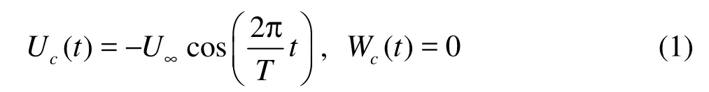
The aim of this study is to predict two-dimensional fluid motion induced by the oscillation of a circular cylinder (Case 1) and a diamond prism (Case 2) of the same cross-stream dimension D=0.01m in water at rest (see Fig.1). The body is allowed to oscillate only in the longitudinal direction and the body vibrating velocity is given by The considered oscillating flow is controlled by the Reynolds number (Re) and Keulegan-Carpenter number (KC). KC is defined byKC=U∞T/D = 5 (or KC=2πA/D) , whereD is the cylinder diameter, A the oscillation amplitude, T the period of oscillation and U∞the maximum velocity in the oscillation. The Reynolds number for this flow is usually defined as Re=U∞D(zhuǎn)/v =100, v being the kinematic viscosity of the fluid. The flow is affected additionally by the Stokes number which is defined by β=D2/vT[7]where Re is the product of KC and β.
Fig.1 Schematic of the problem domain in-line in a fluid
The body is initially located at the center of the domain so its center has coordinates 15D and 10D. The domain has a length of 30D and a width of 20D. These dimensions were chosen similar to the experiment carried out by Dütsch et al.[9]at the same conditions for an oscillating cylinder to validate the proposed model.
1.2 Governing equations and boundaries conditions
To handle a moving object, there are generally two categories of treatments depending on the chosen frame of reference: inertial or moving frames.
The Navier-Stokes equations governing an incompressible Newtonian fluid flow in an inertial frame connected to the stationary fluid are written as
where ui(u,w) are the velocity components in the directions along the axes coordinatesxi(x,z), p is the pressure, ρ is the density of the fluid, which was fixed to 998.2 Kg·m–3and μ is the dynamic viscosity taken equal to 10–3Kg·(ms)–1for all computations.
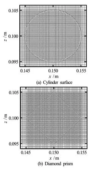
Fig.2 Rectangular meshes refined near the surfaces
In applying these transport equations in the inertial system, the numerical grid has to be moved and adjusted from time step to time step according to the cylinder motion. However, a long distance moving object, the remeshing of the computational fluid domain is difficult[16]. For this reason, the proposed model is based on the Navier-Stokes equations written in an accelerated reference system. The inertialix and accelerated framesare connected by the relationship
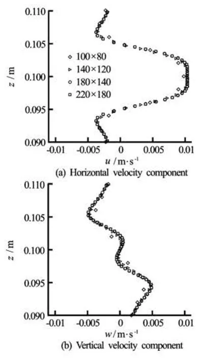
Fig.3 Effect of grid refinement on the velocity components at section x =0.144m at phase timet=T/2+nt
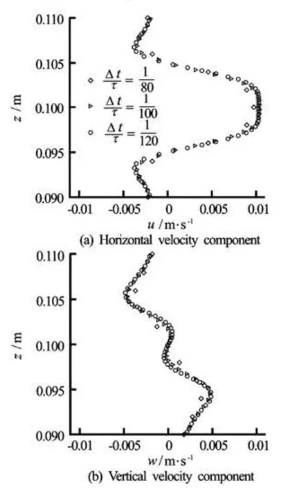
Fig.4 The effect of time step Δt/T on the velocity components at section x=0.144m at phase timet=T/2+nt
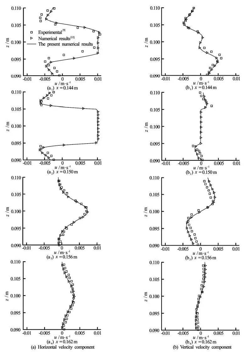
Fig.5 Comparison of the velocity components at four cross sections at timet=T/2+nt
Hence, the fundamental equations for the accelerated system are heredenotes the fluid velocity in the accelerated reference system. The added source termtakes into account the oscillating body acceleration. With this formulation, the grid remainsfixed during the computation. The boundary conditions are changed from the flow induced by the motion of a body to oscillating flow around a body at rest (see Fig.1).The fluid velocities at the inlet, outlet and body surface boundaries,,iBu~, is related to oscillating flow around a fixed body by

The initial values ofthe velocity and the pressure in the whole domain are zero. The computed velocity inaccelerated frameis transformed in the inertial velocity field by velocity of the moving body Ui,c(t).
The instantaneous in-line and transverse force coefficients (non-dimensionalized by 0.5ρU∞2D) are defined as follows
1.3 Numerical method
In this study, the PHOENICS code has been applied to the simulation oftheflow around an oscillating body. The transport equations are discretized by the finite volume method numerical in which the conservation equations are written in an integral form. The solution domain is subdivided into a finite number of control volume and conservation equations are applied to each control volume. The convection term was approximated by a hybrid difference scheme. This code used staggered Cartesian grid arrangement. In the PHOENICS code, the body shape is approximated by the cutting cell approach in a Cartesian grid (see Fig.2(a)).
2. Results an d discussions
2.1 Grid and timeinde pendence
Four grids sizes were tested for the case of an oscillating circular cylinderand three time steps were used to test the grid and time independence (see Figs.1(a) and 2(a)). Non-uniform grid dimensions were used in the x-z plane with the minimum grid size being employed near the body shape. The grid is refined near the surface body to resolve the fine flow structures in the viscous layer (see Fig.2). The effects of different grids on the velocity profiles at x= 0.144 m are shown in Fig.3. For a grid with 180× 140 cells in the x and z directions, the computed results are grid independent. For this grid the time independence study is carried out, and it is observed that the results become time step independent for =TΔ 0.049 s (see Fig.4).
2.2 In-line oscillation of a circular cylinder
The flow field induced by an oscillating cylinder were first simulated in order to validate the proposed model. The predicted velocity componentsat four sections x=0.144 m, 0.150 m, 0.156 m and 0.162 m at phase time t=T/2+nT are shown in Fig.5. The experimental measurements as well as numerical data reported byDütsch et al.[9]are provided in these figures for comparison. The cylinder motion velocity of -U∞cos(2π/Tt ) is also shown in these figures for comparison (at x=0.150 m ). For all velocity profiles, a good agreement is achieved.
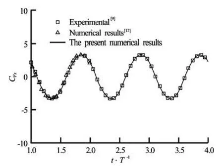
Fig.6 In-line force coefficient as function of the non-dimensional time
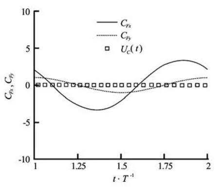
Fig.7 In-line and transverse forces coefficients during one period of oscillation
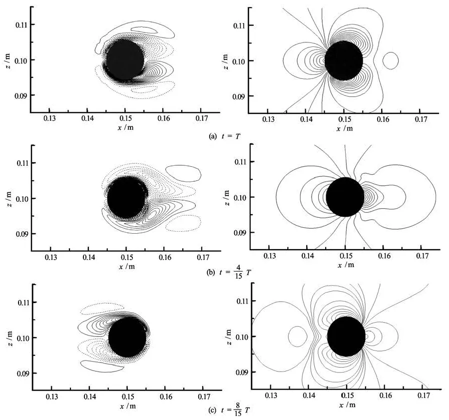
Fig.8Pressure and vorticity isolines for an oscillating circular cylinder at Re=100 and KC =5
Figure 6 shows the in-line force coefficient as function of the non-dimensional time. The present res ults are in very good agreement with the numerical results obtained by Dütsch et al.[9]and Shen et al.[12]. It is found that the instantaneous in-line force signal is highly sinusoidal and periodic, due to the domination of the inertia forces at low KC. Figure 7 shows the in-line and transverse force coefficients and the cylinder velocity (non-dimensionalized by U∞) for one period of cylinder oscillation. There is about 54ophase shift when comparing the in-line force coefficient with the cylinder velocity. Both maximum in-line force coefficient and phase shift agree very well with the numerical results from Dütsch et al.[9]. Hence, the transverse coefficient is equal to zero, indicating a symmetrical flow patterns at low KC. By following Tatsuno and Bearman[7], the parameter set of the present investigation (Re=100 andKC=5) correspond to regime A. This flow regime is stable, symmetric and is characterized by a periodic vortex shedding. Therefore, the transverse coefficient as function of the non-dimensional time is equal to zero, reflected a symmetric pattern of vortical flow formation (see Fig.7). The process of the vortex formation is illustrated by the pressure and vorticity isolines in Fig.8 during the forward and backward motion of the oscillating cylinder. As the-oscillating cylinder moved in the forward direction, at the front of the cylinder an upper and lower boundary layer flows are developed, which are separated at the same upper and lower positions on the cylinder wall. The separating flow produces two counter rotating vortices of apparently the same magnitude of strength, and hence resulting in the same vortex shape. On the upper side of the cylinder a clockwise rotating vortex r emains attached to the cylinder and on the lower side, there is a counterclockwise vortex. In addition, the backward motion of the cylinder caused a splitting of the vortex pair, which was produced by the forward motion and there is inversing in the vorticity sign. The symmetrical flow is also indicated by the velocity fields and streamlines for three times of the cylinder motion, shown in Fig.9.
2.3 In-line oscillation of diamond prism
In this section, the flow induced by an oscillating diamond prism in fluid at rest is considered. The numerical simulation was conducted in the same computational domain shown in Fig.1(b) and the grid refinement, used for this case, near the body surface is shown in Fig.2(b). The diamond prism of diameter D=0.01 m is allowed to oscillate only in the longitudinal direction with the same cylinder vibrating velocity.
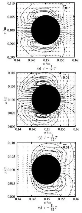
Fig.9 Velocity vectors and streamlines in the vicinty of the circu lar cylinder atRe=100 and KC=5
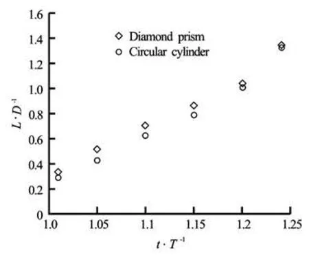
Fig.10 Length of the separation bubble of the flow aroundat Re=100 and KC=5
To get a quantitative check of the flow field property, the length of the recirculation zone for the oscillating diamond prism and cylinder, defined by the dista nce from its basis to th e saddle point related to the two contra rotating vortex zone in the near wake, is plotted in Fig.10 as a function of time. This figure shows that the length of the recirculation of the two bodies shape increase almost linearly. However, for a fixed time, it can be seen that the diamond prism increases slightly the length of the recirculation, as compared with that due to the cylinder.
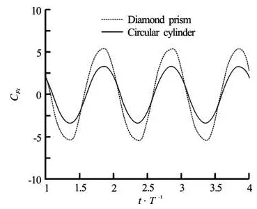
Fig.11 In-line force coefficient as function of the non-dimensional time
The in-line force coefficient on the oscillating diamond prism and the cylinder is shown in Fig.11. The two in-line force coefficient curves are similar and nearly sinusoidal because of the domination of the inertia forces. However, the maximum in-line force coefficient on the oscillating diamond prism is greater than the oscillating cylinder. In fact, for a cylindrical shape the length of recirculation zone is smaller (see Fig.10) and streamlines remains attached to the body for longer distance. Moreover, there is about 5ophase shift when comparing the in-line force coefficient on the oscillating diamond prism with that of the oscillating cylinder.
The numerical predictions of vorticity isolines around the oscillating diamond prism during the forward and backward motion of the oscillating diamond prism are shown in Fig.12. This figure shows a symmetric pair of vortices are formed from the movement of the diamond prism and they remain attached to the leeward face of the diamond prism indicate a symmetrical flow about the line of diamond prism motion.
3. Conclusions
In this study, the flow around an oscillating circular cylinder and diamond prism has been simulated by solving the incompressible Navier-Stokes equations with the PHOENICS code. For both body shapes, the parameter set of the present investigation is Re=100 and KC=5. For oscillating cylinder, good agreement is obtained between the predicted results, experimental and numerical results available in litterature. The periodic vortex consisting of vortices withsymmetric locations around the oscillating cylinder has been well predicted. Moreover, comparison between cylinder and diamond prism show that forin the latter the maximum in-line force and the separation length increase.
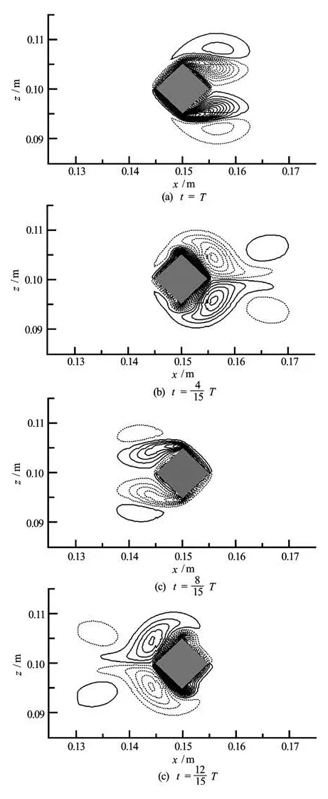
Fig.12 Vorticity isolines for an oscillating diamond prism at Re=100 and KC=5
Finally, it has to be emphasized that the present results have proved the applicability and accuracy of the fixed-grid approach to simulate flow around an oscillating body. From the viewpoint of computational cost, this approach has an attractive advantage as it is well known that the remeshing process requires a great amount of computational time since the movinggrid was adopted.
Also, results have shown that the hydrodynamic characteristic of oscillating bodies depend strongly on the shape of the bluff body. This work would help bette r understand the physics of the flow around sharp-edged cylinders. Also, the presented results can be a good basis for reduction of the wake instability in the sharp-edged cylinders case. Further research should be investigated the flow around an oscillating square prism at different attack angles to determine the optimum body configuration.
[1] SWAROOP A. Design of vortex flow meter[D]. Master Thesis, Delhi, India: Indian Institute of Technology Delhi, 1990.
[2] NORBERG C. Fluctuating lift on a circular cylinder: Review and new measurements[J]. Journal of Fluids and Structures, 2003, 17(1): 57-96.
[3] WANG Jia-song. Flow around a circular cylinder using a finite-volume TVD scheme based on a vector transformation approach[J]. Journal of Hydrodynamics, 2010, 22(2): 221-228.
[4] KU X., LIN J. Numerical simulation of the flows over two tandem cylinders by lattice Boltzmann method[J]. Modern Physics Letters B, 2005, 19(28-29): 1551- 1554.
[5] ZOU Lin, LIN Yu-feng and LU Hong. Flow patterns and force characteristics of laminar flow past four cylinders in diamond arrangement[J]. Journal of Hydrodynamics, 2011, 23(1): 55-64.
[6] GHADIRI-DEHKORDI Behzad, SARVGHADMOGHADDAM Hesam and HOURI JAFARI Hamed. Numerical simulation of flow over two circular cylinders in tandem arrangement[J]. Journal of Hydrodynamics, 2011, 23(1): 114-126.
[7]TATSUNO M., BEARMAN P. W. A visual study of the flow around an oscillating circular cylinder at low Keulegan-Carpenter numbers and low Stokes numbers[J]. Journal of Fluid Mechanics, 1990, 211: 157-182.
[8]LIN J.-C., ROCKWELL D. Quantitative interpretation of vortices from a cylinder oscillating in quiescent fluid[J]. Experiments in Fluids, 1997, 23(2): 99-104.
[9] DüTSCHH., DURST F. and BECKER S. et al. Low-Reynolds-number flow around an oscillating cylinder at low Keulegan-Carpenter numbers[J]. Journal of Fluid Mechanics, 1998, 360: 249-271.
[10] ZHENG Z. C., ZHANG N. Frequency effects on lift and drag for flow past an oscillating cylinder[J]. Journal of Fluids and Structures, 2008, 24(3): 382-399.
[12] SHEN L., CHAN E.-S. and LIN P. Calculation of hydrodynamic forces acting on a submerged moving
object using immersed boundary method[J]. Compu- ters and Fluids, 2009, 38(3): 691-702.
[13] LU X.-Y., SATO J. A numerical study of flow past a rotationally oscillating circular cylinder[J]. Journal of Fluids and Structures, 1996, 10(8): 829-849.
[14] ZHENG W., DALTON C. Numerical prediction of force on rectangular cylinders in oscillating viscous flow[J]. Journal of Fluids and Structures, 1999, 13(2): 225-249.
[15] BEARMAN P. W., GRAHAM J. M. R. and OBASAJU E. D. et al. The influence of corner radius on the forces experienced by cylindrical bluff bodies in oscillatory flow[J]. Applied Ocean Research, 1984, 6(2): 83-89.
[16] TEZDUYAR T. E., BEHR M. and LIOU J. A new strategy for finite element computations involving moving boundaries and interfaces–The deforming-spatialdomain/space-time procedure[J]. Computer Methods in Applied Mechanics and Engineering, 1992, 94(3): 339-351.
10.1016/S1001-6058(11)60302-8
* Biography: GHOZLANI Belgacem (1982-), Male, Ph. D. Candidate, Physics Instructor

- 水動力學(xué)研究與進(jìn)展 B輯的其它文章
- EFFECT OF SWEEP AND EJECTION EVENTS ON PARTICLE DISPERSION IN WALL BOUNDED TURBULENT FLOWS*
- MOTION OF TRACER PARTICLES IN A CENTRIFUGAL PUMP AND ITS TRACKING CHARACTERISTICS*
- EXPERIMENTAL STUDY HYDRAULIC ROUGHNESS FOR KAN TIN MAIN DRAINAGE CHANNEI IN HONG KONG*
- EFFECTS OF LIQUID COMPRESSIBILITY ON RADIAL OSCILLATIONS OF GAS BUBBLES IN LIQUIDS*
- SUPERCAVITY MOTION WITH INERTIAL FORCE IN THE VERTICAL PLANE*
- PARAMETRIC IDENTIFICATION AND SENSITIVITY ANALYSIS FOR AUTONOMOUS UNDERWATER VEHICLES IN DIVING PLANE*