NOVEL APPROACH TO LOCATOR LAYOUT OPTIMIZATION BASED ON GENETIC ALGORITHM
Wu Tiejun,Lou Peihuang,Qin Guohua
(1.College of Mechanical&Electrical Engineering,NUAA,29 Yudao Street,Nanjing,210016,P.R.China;2.Department of Electronics&Mechanical Engineering,Dongguan Polytechinic Institute,Dongguan,523808,P.R.China;3.Department of Aeronautical&Manufacturing Engineering,Nanchang Hangkong University,Nanchang,330063,P.R.China)
INTRODUCTION
Fixtures are used to locate and constrain a workpiece during a machining operation.Proper fixture design is crucial to guarantee the machining requirements of the workpiece.Functions of such devices aim at locating and ensuring the desired positions and orientations of workpieces during the manufacturing process.It is therefore important to configure the locator layout.In practice,the design of a fixture relies heavily on the designer′s expertise and experience due to some uncertain factors.So it is difficult to evaluate the performance of a fixture and in turn,determine the optimal one.
A design method of locating layout for workpiece with arbitrary surface is presented based on the fuzzy judgment.Firstly,the feasible locating reference and locator numbers are automatically selected based on the fuzzy evaluation matrix.And then the locator positions are optimized on the selected locating reference by genetic algorithm(GA).
Many efforts have been done into fixture locator layout determination. Gules in[1]established a system of automatic selection of the locating surfaces for prismatic workpiece based on 3-2-1 guideline.Wayne et al[2]proposed a method to conduct a robust fixture design to minimize workpiece positional errors as a result of workpiece surface and fixture setup errors.Li and Melkote[3]used a nonlinear programming method to solve the layout optimization problem.The method minimized workpiece location errors due to the localized elastic deformation of the workpiece.Choudhuri et al[4]presented a model and analyzed the influence of the accuracy of locators on geometrical tolerance of workpiece.Asada et al[5]used a Jacobian matrix to formulate the relationship between the fixture displacements and workpart displacements. Rong et al[6]established three perpendicular locating reference planes based on locator types and positions.Locator displacements were mapped into the deviations of locating reference planes. The machining surface deviation was then calculated based on the locating reference plane deviations.Marin et al[7]presented a method to determine the tolerance of the error in the contact zone between fixture and components so that a given geometric tolerance was satisfied.Qin et al[8]presented a mathematical model based on locating principle,and then analyzed the correctness of the locating scheme according to the solution construction of homogenous linear equations. Kulkarni and Pande[9]used a feature-based model and generated initial setups by performing systematic reasoning of part model,inter feature relations,tolerance relations and expert rules.Michael[10]introduced a method to compute the optimal set of locators,among an initial finite discrete set of candidates,which minimized the position inaccuracy of the work part.This inaccuracy was shown to depend on the so-called information matrix of the locator scheme.Ong and Nee[11]used fuzzy set theory together with production rules in automatic setup planning for machining of prismatic parts on vertical machining centre.Raghu and Melkote[12]presented a model to analyze the position and orientation of the workpiece after loading based on fixture geometric error,then to calculate the final position of component from the deformation of the fixture-workpiece system.
Most of the above studies use a mathematical model to analyze some locating planning,then optimize these locating planning with linear or nonlinear programming methods.All of the fixture layout optimization procedures start with an initial feasible layout.Solutions from these methods are dependent on the initial fixture layout. The literature review reveals few researches on the automated initial locating layout planning.
The paper presents a fuzzy-evaluation-based algorithm for initial planning of locating points,then for optimum locating planning with GA.Minimizing locating errors as the goal,a set of locating positions are decided for a 3-D object with arbitrary shape.
1 AUTOMATION OF LOCATOR LAYOUT SCHEME
The fix ture design is a complex process including a few uncertain factors.It is difficult to obtain the best fixture design results.Therefore,a fuzzy judgment matrix is first constructed to analyze every candidate surface.When degree of freedom(DOF)of the workpiece can correctly be constrained, the initial locator number is determined.Otherwise,the candidate surface is continued to be analyzed until the constrained freedom meets the machining requirements.To some special workpieces, for example sheet metal,the above steps is able to constrain all the undesired DOFs of the workpiece.But it is not well satisfied with the machining requirement.The design should add the auxiliary supporter.Finally,the locator position is optimized by GA.The whole design process is shown in Figs.1-2.
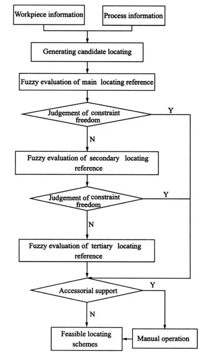
Fig.1 Flowchart of selection of locating reference
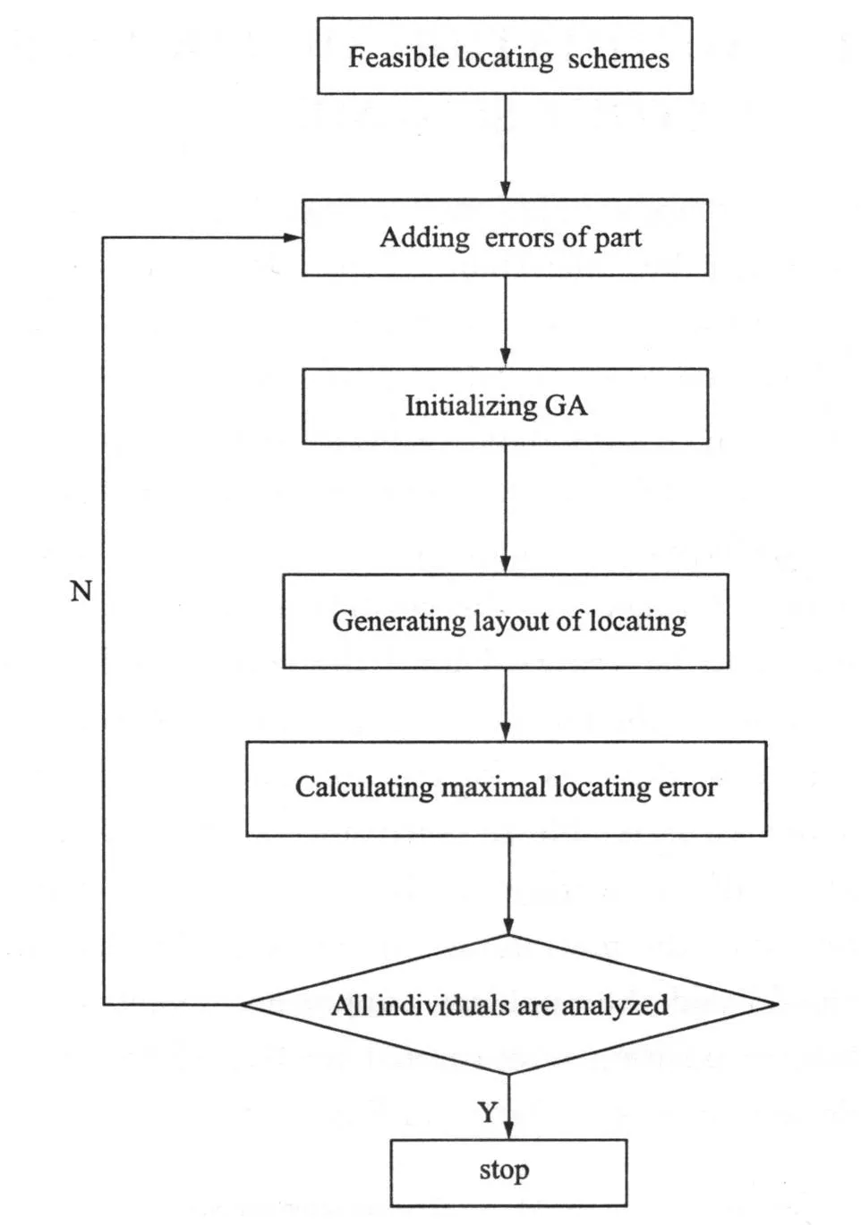
Fig.2 Flowchart of GA
2 DOF CONSTRAINT MODEL OF WORKPIECE
A workpiece has six DOFs in orthogonal coordinate system. In order to guarantee the design specification of the machining feature of the workpiece,some DOFs must be constrained to obtain the reasonable location of the workpiece with respect to the cutting tool.The essential constrained DOFs are named as the theoretical constrained DOFs.The relationship between the theoretical constrained DOFs and the design specification of the machining feature is represented as

where W rpis the machining error measuring the design specification, f r1the theoretical constrained DOFs, and Epthe configuration matrix at the process point r p=[x p,y p,z p]Twhose expression is

It is well known that the theoretical constrained DOFs are eliminated by a feasible locating scheme. Here,an arbitrary locating scheme is assumed to consist of k(i=1,2,…,k)locators,as shown in Fig.3[13].In Fig.3,the workpiece coordinate system (WCS)and the global coordinate system(GCS)are given.n i=[nix,niy,niz]Tis the unit normal vector of the workpiece surface at the i th contact point ri=[xi,yi,zi]T.Thus,its practical constrained DOFs of the workpiece whose formulation can be referred to Ref.[14]in detail is rewritten as

where f r2is the practical constrained DOFs and J the locating Jacobian matrix,and its expression can be concluded as

The correctness of the designed locator layout depends on the logic relationship between f r1and f r2.If f r1∩ f r2=f r1,f i=0.9.If f r1∩ f r 2=f r1, f i=0.8. If f r1∩ f r2≠O,f i=0.4.Otherwise,fi=0.
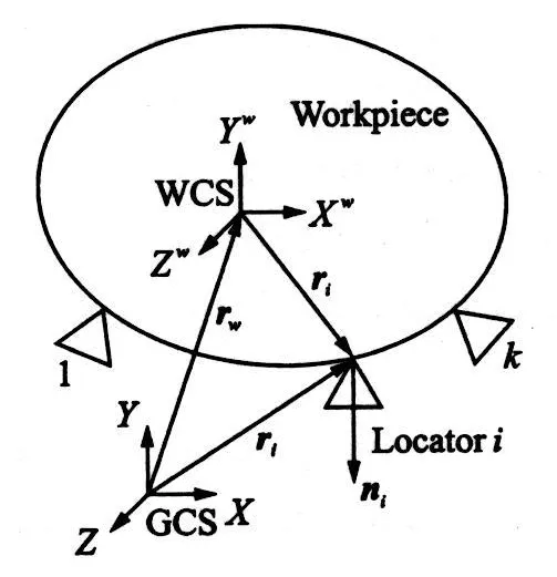
Fig.3 Fixture locating scheme
3 DETERMINATION OF OTHER EFFECT FACTORS
In addition to the logic relationship between the theoretical constrained DOFs and the practical constrained DOFs,generally speaking,the effect factors of locator layout design also include following five aspects.
3.1 Distance
If the mass center of a workpiece is projected onto the i th locating reference,the obtained point is defined as the projected mass center.The ratio of the distance from the projected mass center to the geometric center of the locating reference is w rit ten as

where li is the distance from the projected mass center to the geometric center of the i th locating reference,and l max the maximum distance.
3.2 Surface roughness
The smaller the roughness value is,the larger the performance norm is.Compute the degree of membership with ascending exponent fuzzy distributing function as
where Ri is the roughness value of the i th locating reference.
3.3 Position tolerance
The position tolerance is usually ignored when the designer presents the locator layout.In fact,the smaller the position tolerance is,the higher the locating accuracy is.The value can be determined as
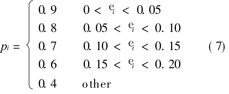
where e i is the position tolerance of the i th locating reference.
3.4 Surface type
A workpiece consists of avariety of surfaces.Here,these surfaces are categorized into plane surface, cylindrical surface, conical surface,curved surface and other surfaces.Thus,the ratio of surface type denoted by tiis shown in Table 1.
3.5 Surface area
Supposing that si is the surface area of the i th locating surface,the area ratio of locating reference can be defined as

4 DETERMINATION OF WEIGHT SET
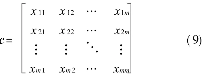
Letting xi be an effect factor on locator layout determination(i.e.,xi=di,pi,ti,qi and f i),xij is defined as the important factor of xi with respect to x j.Their values can be selected from 1 to 9 according to the compassion of their importance with each other,as listed in Table 2.Thus,the ration matrix can be constructed as
with xii=1,xij=1/x ji.
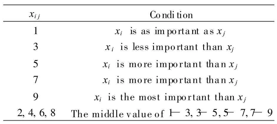
Table 2 Scaling value
It is known that the eigenvalues of the ratio matrix can be used to identify the consistency of xij in the practical problem.If the ratio matrix has good consistency,the weight coefficient of all effect factors can be obtained. Otherwise,xij should be adjusted until its value makes the ratio matrix to be good consistency.
Let y=[y1,y2,…,ym]Tan eigenvector of the ratio matrix c, a new vector can be constructed as

If the non-negative components number in d equal to the column number of c,the consistency of the ratio matrix with the practical problem is good.Otherwise,the component in the matrix c must be adjusted until the matrix meet the requirement of consistency.
In the traditional analytic hierarchy process(AHP),the weight set of the matrix with consistency is solved by the root method or the least square method.The algorithm is shown by Eqs.(11-12).


5 LOCATING LAYOUT OPTIMIZATION
Consider the locating problem of the 3-D workpiece.As shown in Fig.4,a certain surface is discretized to a series of points.The locator position is the design variable.
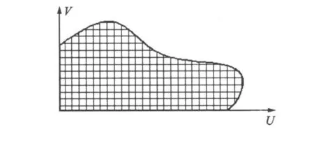
Fig.4 Generation of candidate locating points
The position can be optimally selected with GA as follows:
Step 1 Generation of initial locator positions.
By random selecting initial points from the discretized points,the initial locator positions are generated.Of course,three points laid out on the uniform surface cannot be collinear.In addition,the mass center must be projected within the triangle configured by the three points.
Step 2 Improvement of initial locator positions.
Because the initial locator positions can cause the poor locating accuracy, GA is used to regenerate the initial locator positions so that the locating error can be improved to be minimal.
Step 3 Selection of optimal solution.
Applying GA for each feasible set of locators we will end up with several distinct solutions in the layout scheme of locating positions.Thus,the final solution may not be unique,due to the fact that the optimization problem may have many local optima.The procedure operates on step-bystep basis to seek for an optimal solution.Depending on the objective function pursued the best solution can be evident or might need the designer′s final decision.
6 CASE STUDY
In this section, a typical example is illustrated to validate the proposed approach.The workpiece is made up of some complex surfaces which are accessible to the locators,as shown in Fig.5.The features to be produced area step and a hole with the diameter of 12 mm.The candidate locators are restricted to a set of discrete positions,which are generated as uniformly as possible on the part surfaces.The determination procedure of locator layout is as follows:
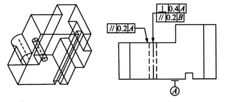
Fig.5 Test workpiece
Step 1 Determination of effect factors.
According to the effect factors di,ri,pi,ti,ai and fi, a effect factor matrix V can be constructed.Here,surfaces A and B are initially selected as the first locating reference and the second locating reference,respectively.Thus,their corresponding effect factor matrixes V1 and V2 are obtained as
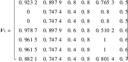
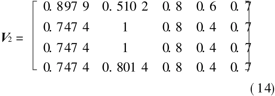
Step 2 Determination of weight set.
According to Eq.(9),the ratio matrices can be written as
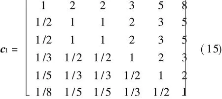
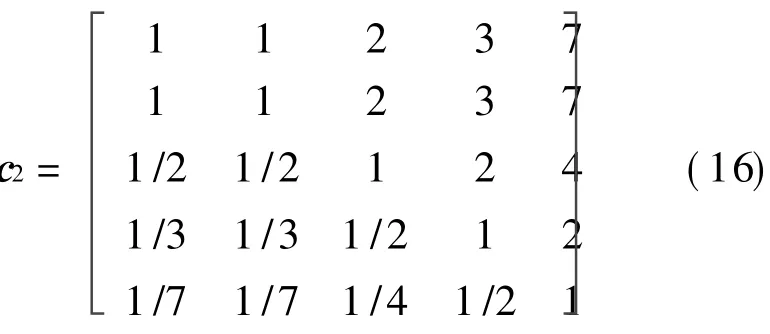
Consequently, the corresponding eigenvectors of c1 and c2 can be calculated as


The maximal eigenvectors of the two matrixes are both close to the exponent number of matrix and other eigenvectors are all close to zero.So without adjustment of the element of the matrix,the weight set can be directly computed as


Therefore,we can obtain the following selection sets


Step 4 Optimization of locator layout.
The entire flowchart of GA is shown in Fig.2.GA input parameters used in this study is given in Table 3.The value of objective function is shown in Fig.6.Results are given in Table 4.
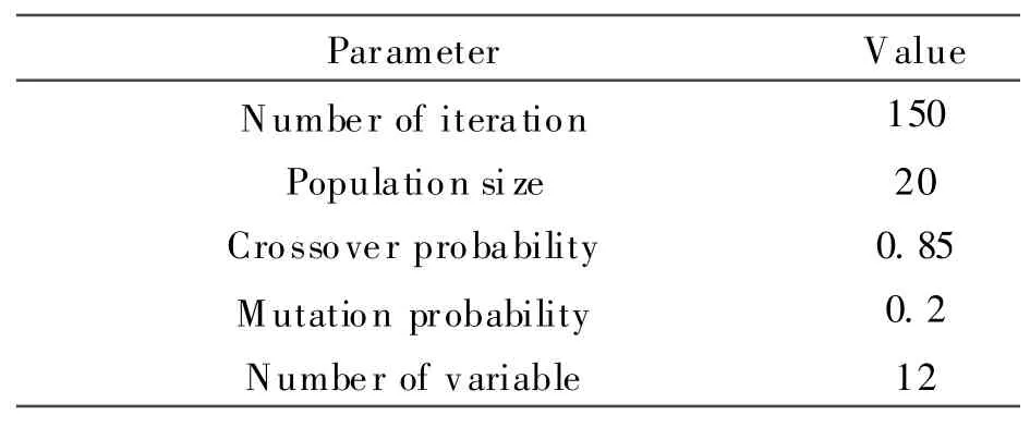
Table 3 GA input parameters
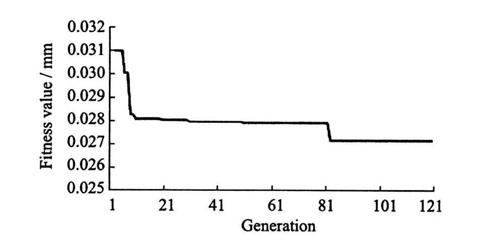
Fig.6 Convergence of GA for locator layout optimization procedure
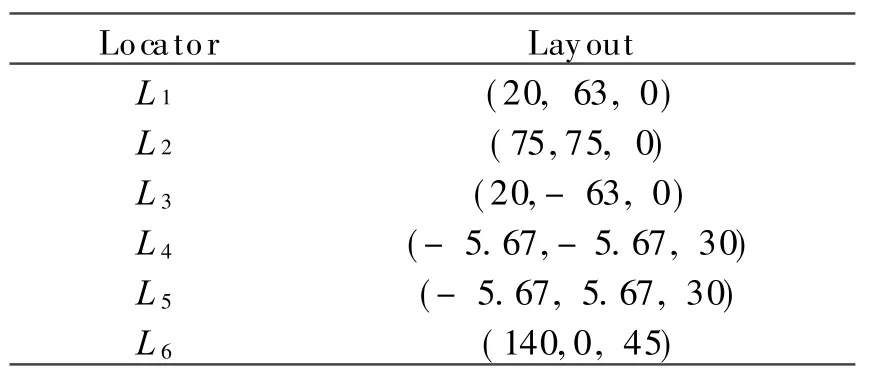
Table 4 Optimum layout obtained by GA
7 CONCLUSION
The accurate position of the workpiece with respect to the cutting tool is crucial to guarantee the design specification.However,this precise position depends on acceptable locator layout.A GA-based approach to locator layout optimization is concerned. An initial locator layout is first obtained based on fuzzy mathematics.And then the optimal locator layout is fast achieved with GA.The appraoch can be used to determination of locator layout of a workpiece with arbitrary surfaces.
Step 3 Selection of locating reference.
Here,a new concept is introduced to select the locating reference.If the effect factor matrix V and the weight set w are known,the selection set can be defined as
[1] Gulesin M.Fixturing for mechanical prismatic parts with the input of 3-D CAD data in the STEP standard [C]//Proceedings of the 1997 IEEE International Symposium on Intelligent Control.Istanbul,Turkey:IEEE,1997:403-408.
[2] Wayne C,Hu S J,Yuan JX.A variational method of robust fixture configuration design for 3-D workpieces[J].Journal of Manufacturing Science and Engineering,1997,119(4A):593-602.
[3] Li Bo,Melkote S N.Improved workpiece location accuracy through fixture layout optimization [J].International of Journal of Machine Tools and Manufacture,1999,39(6):871-883.
[4] Choudhuri S A,De Meter E C.Tolerance analysis of machining fixture locators [J]. Journal of Manufacturing Science and Engineering,1999,121(2):273-281.
[5] Asada H,Andre B.Kinematic analysis of workpart fixturing for flexible assembly with automatically reconfigurable fixtures[J].IEEE J Rob Autom,1985,1(2):86-94.
[6] Rong Y,Li W,Bai Y.Locating error analysis for computer-aided fixture design and verification[C]//Proceedings of the International Computers in Engineering Conference and Database Management Symposium.Boston,MA,USA: ASME,1995:825-832.
[7] Marin R A,Ferreira P M.Analysis of the influence of fixture locator errors on the compliance of work part features to geometric tolerance specifications[J].Journal of Manufacture Science Engineering-Technology,2003,125(3):609-616.
[8] Qin Guohua,Hong Lianhuan,Wu Tiejun.Analysis technology of degrees of freedom of workpiece based on homogenous linear equations[J].Computer Integrated Manufacturing Systems,2008,14(3):466-469.
[9] Kulkarni V S,Pande S S.TM S—An object oriented feature based tolerance modeling system [C]//Winter Annual Meeting of the American Society of Mechanical Engineers. Anaheim, CA, USA:ASME,1992:545-552.
[10]Michael Y W.Automated fixture layout design for 3D workpieces[C]//Proceedings of the 1999 IEEE Conference on Robotics and Automation.Detroit,MI,USA:IEEE,1999:1577-1582.
[11]Ong S K,Nee A Y C.Automatic setup planning in machining operation[J].Journal of Material Process Technology,1997,63(3):151-156.
[12]Raghu A,Melkote S N.Modeling of workpiece location error due to fixture geometric error and fixture-workpiece compliance [J]. Journal of Manufacture Science Engineering Technology,2005,127(1):75-83.
[13]Qin Guohua,Zhang Weihong,Wan Min. A machining-dimension-based approach to locating scheme design [J].Transactions of the ASME Journal of Manufacturing Science and Engineering,2008,130(5):101-108.
[14]Qin Guohua,Wu Zhuxi,Lu Yuming. A novel determination algorithm of locating parameters for fixture design [J]. Key Engineering Materials,2009,407/408:94-98.
 Transactions of Nanjing University of Aeronautics and Astronautics2011年2期
- Transactions of Nanjing University of Aeronautics and Astronautics的其它文章
- PHENOLIC ANTIOXIDANTS DETERMINATION IN FOOD ITEMS USING REVERSED-PHASE HPLC
- APPROXIMATION OF INTERVAL BEZIER SURFACES
- STUDY ON OPTIMIZATION OF HIGH PERFORMANCE CONCRETE ADMIXTURES
- ANALYSISOF UN-COINCIDE COORDINATE ERROR IN SINGLE-AXISROTATING FIBER OPTIC STRAPDOWN INERTIAL NAVIGATION SYSTEM
- SI-INSPIRED ENERGY AWARE QoSROUTING TREE FOR WSN
- COMPENSATION CONTROL OF REAL-TIME UNBALANCE FORCE FOR ACTIVE MAGNETIC BEARING SYSTEM
