
COMPENSATION CONTROL OF REAL-TIME UNBALANCE FORCE FOR ACTIVE MAGNETIC BEARING SYSTEM
2011-10-08 12:09:54GaoHuiXuLongxiangZhuYili
Gao Hui,Xu Longxiang,Zhu Yili
(College of Mechanical and Electrical Engineering,NUAA,29 Yudao Street,Nanjing,210016,P.R.China)
INTRODUCTION
Compared with classical bearings, active magnetic bearing(AMB)has been used widely in modern industry,medical machinery,aeronautics and astronautics because of its active control,no mechanical contact,no friction,no lubrication and high speed[1].AMBis the chief component of multi-electric aircraft and aero-motor.However,just as the ordinary rotary device,AMB system also has the impact on unbalance stimulation synchronous with rotor rotational frequency because of the rotor mass eccentricity and the principal axis of inertia being not coincident with the axis of geometry.Under the action of active control,the rotor would be restrained by AMBs and spin around one unknown axis between the inertial axis and the geometrical axis.So,there are two kinds of unbalance vibration in AMB system.Oneis force unbalance vibration,and the other is displacement vibration.The method for eliminating or weakening force unbalance vibration is called the force unbalance force compensation,that is,let the rotor spin closer to the inertial axis by means of weakening the effect of active control. The active control can be weakened by reducing the amplitudes of the control currents[2-9]. The other method of restraining displacement vibration is called the unbalance displacement compensation,that is,let the rotor spin closer to the geometrical axis through enhancing active control[10-12].Directed towards unbalance force compensation,there are two schemes, one is closed-loop feedback compensation[2,7], and the other is open-loop feed-forward compensation[3-6,8-9]. The merit of the first scheme is that it can filter directly the unknown displacement signals at some fixed frequency,and the drawback is increasing the exponent number of feedback control system and reducing system stability. The merit of the second scheme is that it will not increase the unstable factor of closed-loop system.But it is difficult to provide the needed sinusoidal compensation signal having the same frequency and amplitude as rotor displacement signal besides reverse phase.
Herzog et al[2]proposed a generalized narrow band notch filter which was inserted into the closed-loop feedback system. Shafai et al[3]introduced a novel method called the adaptive forced balancing(AFB)which solved the problem of synchronous vibration. Mohamed et al[4]proposed a controller design methodology using the Q-parameterization theory for variable speed magnetic bearings in order to achieve elimination of unbalance vibrations. Huang et al[5]used compensatory voltage vectors with proper amplitudes and phases as the input of the power amplifiers to cancel out the effect of the rotor imbalance.LMS adaptive filter algorithm also was applied in autoba lance[6-9], which could eliminate the sinusoidal displacement signals,reduce the amplitudes of the output control currents of power amplifiers,weaken the active control,and achieve adaptive force compensation.LM S algorithm is adaptive to filter some unknown signals. At home, Zhang et al[6]mentioned the application of LMS algorithm in AMB system.Gao et al[7]implemented closed loop feedback unbalance force compensation control in AMB system by adopting LMS algorithm.At abroad,Kang and Shi et al[8-9]also applied this method in AMB system.Ref.[8]implemented single-DOF experiment,and Ref.[9]only achieved compensation for four radial DOFs in fixed rotational frequency(26.37 Hz).Refs.[6-9]analyzed the vibratory force only from fixed frequency,but did not research the real time unbalance force compensation.The reasons of those maybe it will produce complicated or nonlinear relation among filter algorithm,corresponding controller and AMB system,thus cannot satisfy the filter requirement in all bandwidth.
Directed towards the deficiency of Refs.[6-9],this paper analyzes the principle of adaptive filter of LMS algorithm and the relation between algorithm step-size and rotor rotational frequency combining with the time-variable feature of rotor displacement signals.Furthermore,one new real time feed-forward compensation scheme is proposed to adaptively weaken four radial unbalance force.A new variable step-size LMS algorithm is utilized as the feed-forward compensation controller to provide requisite sinusoidal compensatory signals. Firstly,rotor displacement signal is kept as algorithm expectant signal and the needed algorithm output signal is obtained after several times of iteration,then the reverse signal of algorithm output as the output signal of the feed-forward controller is injected into the closed-loop system of AMB. The stability of original control system will not be reduced by the added feed-forward controller,so it can implement real-time unbalance force compensation for four radial DOFs when AMB system works normally.Finally,the feasibility of the new method for the adaptive compensation of the vibration of AMB system is verified by the experimental results.
1 SCHEME OF FEED-FORWARD COMPENSATION
1.1 Feed-forward structure based on LMS algorithm
The structure of feed-forward compensation control based on LMS algorithm is given in Fig.1. The added sinusoidal unbalance information is provided by LMS adaptive algorithm according to rotor feedback signals.LMS algorithm is adopted for its several merits,such as simple structure,moderate operations,and without mathematical model of the processed objects.Relative to Refs.[3-5],the sinusoidal compensatory signals are ex tracted adaptively only by LMS algorithm instead of contrived given or some other signal generating algorithms.
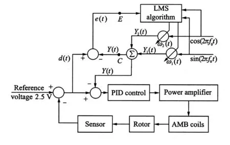
Fig.1 Adaptive feed-forward compensation control based on LMS algorithm
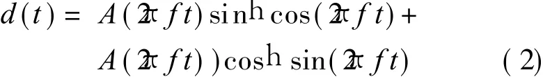
The sinusoidal rotor displacement fluctuation of AMB system caused by the rotor mass eccentricity at high speed can be supposed by

where A(2πft)is the function of displacement signal amplitude,f the rotational frequency of rotor, and h the initial phase, which is determined by the rotor initial position.Eq.(1)is expanded by
Let A(2πft)sin h=a1(t),A(2πft)cos h=a2(t),Eq.(2)can be replaced by

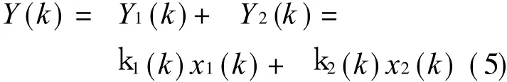
Therefore,the signal d(t)can be processed by LMS algorithm. The structure of LM S algorithm is shown in Fig.1.X(t)=[sin(2πf 0t)cos(2πf 0t)]′,W(t)=[k 1(t) k 2(t)]′respectively represent input vector and weight iteration vector of the algorithm,f 0 is the frequency of input signal,Y(t)the output of the algorithm,also the sinusoidal feed-forward compensatory signal.According to Ref.[13],discrete analysis of the downside branch of LMS algorithm is shown in Fig.2.
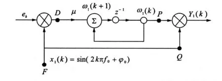
Fig.2 Algorithm single transmission
In Fig.2,_is the step-size,and the weight coefficient iterative function of the downside branch from D to P can be given by

From Figs.1-2,the following two functions are given

Eqs.(4-6)are the discrete analysis.When t→+ ∞ ,if guaranteeing k1(t)→ a1(t)and k2(t)→a2(t)in the process of iteration combining Eqs.(3-6),there has

If conditions are permitted,the needed sinusoidal compensatory signal can be provided by LMS algorithm from Eq.(7),which is the reverse signal of Y(t).The transfer function of closed-loop between e(t)and d(t)can be written from Refs.[13,14]
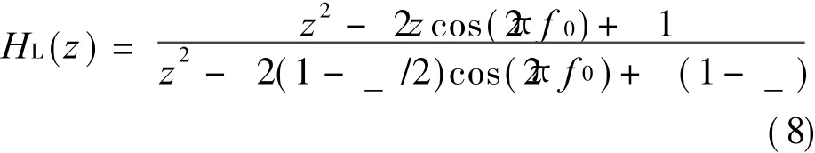
From Eq.(8),the zeros of H L(z)are e±2jπf0,which are distributed on the unit circle.Signal tracked completely can be achieved if H L(z)=0 when the frequency of d(t)is equal to f 0,i.e.,Eq.(7)is restricted by f=f0.
PID digital controller with advanced part is used,the controller module is

where K p is the proportional gain,T i the integral gain,T d the differential gain,K p T d s/(1+ T f s)the incomplete differential part,and(T L s+ 1)/(αT L s+ 1)the additional advanced part,here,T<1.The transfer function of the closed-loop controller system is given by
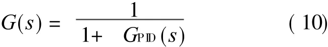
The transfer function of total controller added the feed-forward compensation controller can be calculated by

To prove the validity,the major coefficients of the total controller are configured as follows:_=0.04,f 0=400 Hz,K p=0.685,T i=0.545,T d=0.569,K f=0.753 9,K L=0.074 25,sample frequency is f s=20 000 Hz,and so on.The curves of frequency characteristic of Eq.(11)is simulated by MATLAB in Fig.3.From the curve of amplitude-frequency characteristic,it can be seen that it can filter well at 400 Hz because the output response is less than-100 d B,and the output response is close to 0 d B in additional frequency,which can prove that output tracks system input well. From phase-frequency characteristic curve,it can be seen that the curve is over-180°, so the controller is stable according to log-magnitude versus phase plot.Therefore,the sinusoidal control signal of the input of PID can be compensated when f=f 0.The validity of the scheme of feed-forward compensation can be proved form Fig.3.

Fig.3 Bode diagram of total controller
The part surrounded by circles in Fig.3 is enlarged in Fig.4. Easy to see, the total controller is unstable in the low-frequency region because the corresponding output response is less than-3 d B,but output can perfectly respond the input signal after 300 rad/s(47.8 Hz).That is to say the feed-forward controller is unsuitable for AMB system in low-frequency region.So,in this paper,compensation controller is not added until the rotational frequency reaches the fixed value.
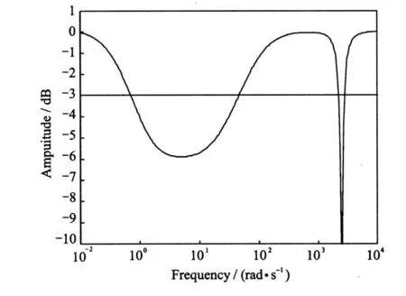
Fig.4 Amplitude-frequency characteristic of restricted part in Fig.3
1.2 Variable step-size of LMS algorithm
According to Section 1.1,it is feasible that LMS algorithm works as feed-forward controller to implement unbalance force compensation.But the effect of LMS filtering is restricted by_.The selected value of_ will directly influence the algorithm convergent velocity and the ability of following the time-variable signal.So the normal LMS with fixed_ cannot satisfy real-time requirement in the unbalance force compensation of AMB system.And it is the reason why Refs.[6-9]only analyzed the application of LMS in force unbalance force compensation in fixed rotational speed.The variable step-size of LMS can be deduced by analyzing the relation among the step-size and the frequency of input signal and the rotor rotational frequency.From the angle of zeros 2πf 0 and Ref.[15],the bandwidth(BW)can be given by
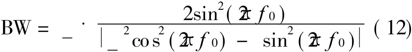
Here,the concept of quality factor is adopted to show the effect of Notch filtering[13]
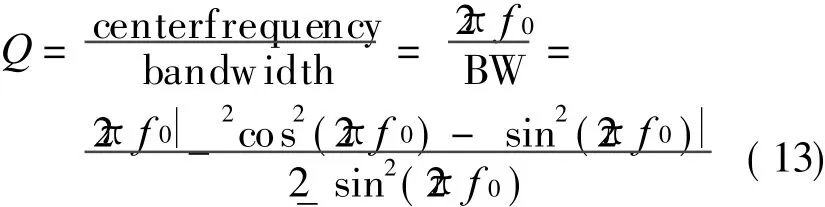
If_? 1,then_2cos2(2πf 0)≈ 0,Eq.(12)can be simplified by
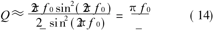
Q is proportional to f 0 and inverse proportional to_.The correctness of Eq.(14)can be proved by the coefficients in Table 1 and the corresponding simulation given in Fig.5.
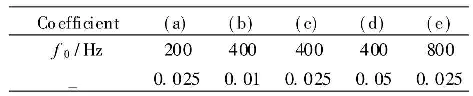
Table 1 Dif fer ent combination of f requ ency and step-size
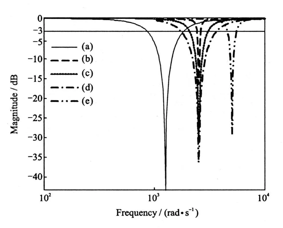
Fig.5 Relation among BW,frequency and step-size
The length between the two nodes of-3 d B beeline and each curve from Fig.5 denotes the BW of each filter which is the smaller the better.In practical and industrial application,to improve the effect of filtering,the value of Q should be selected reasonably and should satisfy the harmonious reason among the three characteristics mentioned of LMS.So_can be represented by f0and Q
From Eq.(15),it can be seen that suitable_is restricted by f0when Q is fixed.In view of the limitations of normal LMS in the application of real-time adaptive compensation and the validity and thoroughness of filtering when f=f 0,now,the new variable step-size function in the application of time-variable feed-forward unbalance force compensation control system of AMBis given by
where_v is the variable step-size,Q f the fixed value according to different AMB system,which is computed by suitable_ and corresponding coefficients of PID controller according to Eq.(15)when implementing force compensation of fixed speed of 300 Hz._is 0.04 and Q f is 23 550 rad/s when the compensatory experiment is operated practically at 300 Hz.
1.3 Real-time unbalance force compensation
According to the analysis of Sections 1.1 and 2.2,one new real-time and on-line feed-forward unbalance force compensation scheme is proposed in Fig.6.
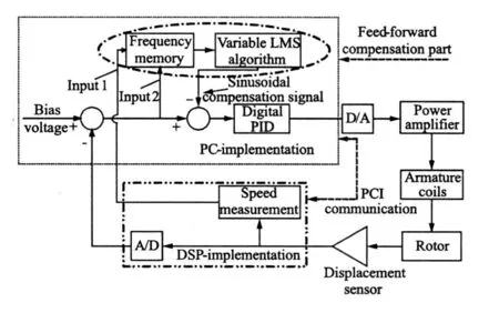
Fig.6 Real-time feed-forward control for unbalance force compensation
The sinusoidal feed-forward compensatory signals are provided by variable step-size LMS algorithm,but they are uncompensated at low frequency until the rotational speed reaches the fixed compensatory frequency.There is a switch control between the process of uncompensation and compensation.The algorithms of digital PID controller and feed-forward compensation according to variable step-size LMS and the switch procedure are implemented by PC.A/D converter and speed measurement are implemented by DSP chip of TM S320LF2407A,and information exchange between them is implemented by PCI9052 card. The period of digital control and sample are all 50μs.Finally,the real-time unbalance force compensation can be achieved.
Fig.7 is the part of switch compensation in Fig.6.Only PID controller works when the rotational frequency is less than f s,and f s is a given value according to needs.Here,it is 300 Hz.Feed-forward controller and PID controller will work simultaneously when the rotational frequencyf reaches or surpasses f s,and real-time and variable-speed unbalance force compensation will beimplemented.
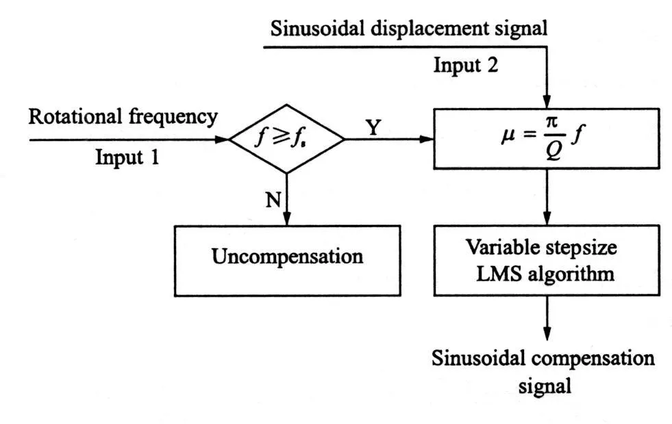
Fig.7 Feed-forward control part for providing sinusoidal compensatory signal
As a major criterion in the processes of compensation and switch control,rotor rotational frequency plays an important role.The process of speed measurement adopts unit of CAP4 in EVB,and sets relevant trigger of capture and period to achieve speed measurement.The measured signal is provided by one of the four radial displacement signals of the AMB system,where the sinusoidal signal having 2.5 V bias is processed to square wave(0—3.3 V)by a processed circuit.
Fig.8 is the simulation of feasibility of the new strategy,and the three curves severally signify the output signal of PID controller,the rotor displacement signal and the feed-forward compensatory signal.Before 0.015 s,there are not feed-forward signals for the compensatory controller is not added and the PID output can respond to rotor signal well.Between 0.015s and 0.03 s,feed-forward compensation is injected when the rotational frequency is given 200 Hz,and the feed-forward signal can follow up the rotor signal,so PID output becomes zero after several periods.Another compensation is shown at 400 Hz after 0.03 s according to Eq.(16),and the phenomenon is similar to foregoing compensation.It can be seen that the changes are stable at the two points of switching from the curve of PID output,which can prove the validity of the new strategy further.From the PID output signal in Fig.8,it can be seen that the unbalance displacement voltage is compensated by the new LMS,which can reduce the unbalance current response in the power amplifier and weaken the periodical constraint for cein the armature coils in Fig.6,and the unbalance force compensation of the rotor system is improved finally. So,eliminating the fluctuation of control current is one important basis for estimating unbalance force compensation.

Fig.8 Simulation of variable-frequency switch feed forward compensation
2 EXPERIMENTAL ANALYSIS
The configuration of the active compensation control system is given in Fig.9.
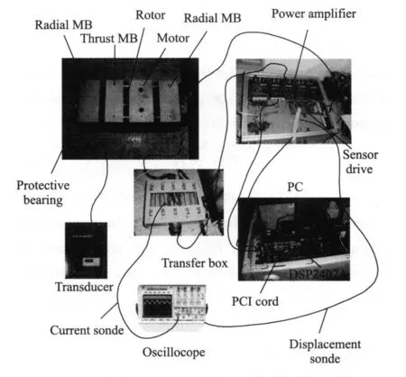
Fig.9 Real closed-loop manipulative system of AMB system
In Fig.9,PC and digital control are the keys of implementing active compensation control.The displacements of rotor are measured by displacement sensors in the skeletons of magnetic bearings(not displayed in Fig.9)and the drive of sensors.The action of transducer is to drive the motor rotation,and the action of transfer box is debugged and measured conveniently.Relevant algorithms are programmed in PC and DSP,according to Eq.(16)and foregoing Qf.Variable step-size is given that_v=f/7 500,and the PID control coefficients are the same as those given in Section 1.1.Now,several pictures are displayed to contrast the effects between compensation and uncom pensation at the rotational frequencies of 300,400,500,550 and 575 Hz.The signals of currents and displacements with and without compensation control are shown in Fig.10.
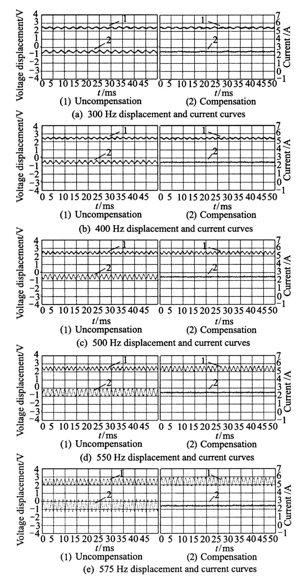
Fig.10 Curves of displacements and currents with and without compensation
In each pair of Fig.10,the abscissa is time axis with the unit of 5 ms/div,and the ordinate represents current axis with the unit of 1.0 A/div and displacement axis with the unit of 1.0 V/div.It can be seen that the curves of control currents tend to be straight lines with compensation.In order to analyze the changes of currents and displacements better, fast Fourier transform(FFT)is utilized to obtain accurate amplitudes of each curve in Fig.10.The FFT curves of currents at different frequency are given in Fig.11,and FFT of displacements are shown in Fig.12.
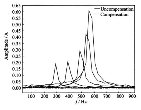
Fig.11 FFT of control currents of with and without compensation
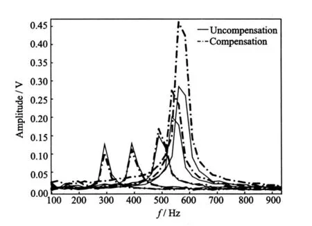
Fig.12 FFT of displacements of with and without compensation
In Fig.11,the amplitudes of the control currents increase as nearly square relationship with the increase of the rotational frequency without compensation.When the rotor rotates at high-speed,even a small increase of the rotation frequency can lead to great change of the amplitudes of control currents.For example,the amplitude of current increases about 0.2 A when the rotation frequency changes from 550 Hz to 575 Hz,but it increases only 0.02 A from 300 Hz to 400 Hz.So,in the high-frequency region,the periodic counterforce acting on the housing of the AMB system through the magnetic bearing coils will increase quickly when rotor rotational frequency is increased.It can increase the housing vibration and noise,reduce the stability of the system,and aggrandize the power dissipation of all magnetic bearings.As the control currents with compensation fluctuate nearby zero line basically,the problems listed above caused by the counterforce can be to great extent settled,and the effect of compensation turns out to be much better in high-frequency region.
From Fig.12,it can see that the rotor displacements in low-frequency region are relatively reduced with compensation, which maybedue to the existence of super-harmonic and sub-harmonic vibrations. While the rotor displacements are accordingly enlarged with compensation in high-frequency region because the rotor turns into the state of free rotation.What is more, the rotor inertial force is proportional to the square of the frequency.In order to balance the increased inertial force,the displacement should be greater than that without compensation.The vibration of AMB system is produced by the inertial force of the rotor from the amplitude of each curve in Fig.11 and Fig.12.It proves the validity of adaptive feed-forward unbalance force compensation with the new variable LMS algorithm, but the vibration decrease is achived by increasing the rotor displacements.
3 CONCLUSION
On the basis of the study of the influence of unbalance stimulation of AMB and the analysis of the disadvantage of the LMS algorithm,a new feed-forward unbalance force compensation strategy of real-time switching control is proposed.The effectiveness and real-time of the new scheme is verified by the rotational experiments.It can weaken the action of active control of AMB system through reducing the amplitudes of the control currents, and implement unbalance force compensation at the cost of increasing the unbalance displacement vibration. It can eliminate the stimulation of unbalance force of rotor especially in high-frequency region effectively,increase the control stability of AMB system,and limit the saturation of control current and losses of eddy current.This scheme provides an effective way to improve the rotational speed in the AMB system.
[1] Yu Lie.The system of rotor of controllable magnetic bearings[M].Xi′an: Science Press,2003.(in Chinese)
[2] Herzog R,Buhler P,Gahler C,et al.Unbalance compensation using generalized notch filters in the multivariable feedback of magnetic bearings[J].Control Systems Technology,1996,4(5):580-586.
[3] Shafai B,Beale S,Larocca P,et al.Magnetic bearing control systems and adaptive forced balancing[J].Control Systems Magazine,1994,14(2):4-13.
[4] Mohamed A M,Matsumura F,Namerikawa T.Q-parameterization control of vibrations in a variable speed magnetic bearing[C]//Proceedings of the 1997 IEEE International Conference on Control Applications. New York, Piscataway: IEEE,Control Applications,1997:540-546.
[5] Huang Xiaowei,Tang Zhonglin.New method for autobalancing with active magnetic bearings[J].Chinese Journal of M echanical Engineering,2001,37(7):99-112.(in Chinese)
[6] Zhang Dekui,Jiang Wei,Zhao Hongbin.Unbalance vibration control methods for active magnetic bearings system [J]. Journal of Tsinghua University,2000,40(10):28-31.(in Chinese)
[7] Gao Hui,Xu Longxiang. Real-time vibration compensation for active magnetic bearing systems based on LMS algorithm[J].Journal of Vibration Engineering,2009,22(6):583-588.(in Chinese)
[8] Kang M S,Yoon W H.Acceleration feed forward control in active magnetic bearing system subject to base motion by filtered-X LMS algorithm[J].IEEE Transactions on Control Systems Technology,2006,14(1):134-140.
[9] Shi J,Zmood R.The direct method for adaptive feed-forward vibration control of magnetic bearing systems[C]//7th International Conference on Control, Automation, Robotics and Vision.Singapore: Nanyang Technological University,2002:675-680.
[10]Bi Chao,Wu Dezheng, Jiang Quan.Automatic learning control for unbalance compensation in active magnetic bearings[J]. IEEE Transactions on Magnetics,2005,41(7):2270-2280.
[11]Jing Minqing,Li Zixin,Luo Min,et al.Unbalance response and touch-rubbing threshold speed of rotor subjected to nonlinear magnetic forces[J].Chinese Journal of Mechanical Engineering,2008,21(2):1-4.
[12]Arias M M,Silva N G.Finiteelement modeling and unbal ancecompensation for a two disks asymmetrical rotor system[C]//2008 5th International Conference on Electrical Engineering,Computing Science and Automatic Control. Mexico City, Piscataway:Electrical Engineering,2008:386-391.
[13]Fu Minshen.Adaptivesignal processing[M].Xi′an:Xidian University Press, 2001: 144-147. (in Chinese)
[14]Vaz C,Kong X,Thako N.An adaptive estimation of periodic signals using a Fourier linear combiner[J].IEEE Transactions on Signal Processing,1994,42(1):1-10.
[15]Xiao Y,Tadokoro Y.LMS-based notch filter for the estimation of sinusoidal signals in noise[J].Signal Processing,1995,46(2):223-231.
 Transactions of Nanjing University of Aeronautics and Astronautics2011年2期
- Transactions of Nanjing University of Aeronautics and Astronautics的其它文章
- PHENOLIC ANTIOXIDANTS DETERMINATION IN FOOD ITEMS USING REVERSED-PHASE HPLC
- APPROXIMATION OF INTERVAL BEZIER SURFACES
- STUDY ON OPTIMIZATION OF HIGH PERFORMANCE CONCRETE ADMIXTURES
- ANALYSISOF UN-COINCIDE COORDINATE ERROR IN SINGLE-AXISROTATING FIBER OPTIC STRAPDOWN INERTIAL NAVIGATION SYSTEM
- SI-INSPIRED ENERGY AWARE QoSROUTING TREE FOR WSN
- NOVEL APPROACH TO LOCATOR LAYOUT OPTIMIZATION BASED ON GENETIC ALGORITHM