ANALYSISOF UN-COINCIDE COORDINATE ERROR IN SINGLE-AXISROTATING FIBER OPTIC STRAPDOWN INERTIAL NAVIGATION SYSTEM
Zhang Ling,Lai Jizhou,Liu Jianye,Lǜ Pin
(Navigation Research Center,NUAA,29 Yudao Street,Nanjing,210016,P.R.China)
INTRODUCTION
The rotating modulation technology is a most promising method to minimize the system cost and improve the performance in the strap-down inertial navigation system (SINS). This technology can reduce the corresponding integration values,improve the status of gradualadding errors and modify the navigation accuracy of SINS.
The significant characteristics of rotating technology are:(1)It varies the output forms of horizontal gyros(x-gyro,y-gyro)when sensing directions are vertical to the rotating coordinate;(2)It can reduce the inertial navigation system(INS)error,which is caused by inertial sensors.In the last several decades, the rotating technology has become domestic and overseas research hot spot. In USA,MK49 rotating system of Sperry Company is selected as the standard inertial navigation system in 1990s[1-2].The domestic institutes working on rotating inertial navigation system mainly include Beijing University of Aeronautics and Astronautics,Nanjing University of Aeronautics and Astronautics, National University of Defense Technology, and Northwestern Polytechnic University and so on[3-6].
The traditional rotating structure has no effect on the z-gyro, which is fixed on the turnable coordinate. The continuous rotation makes the error of z-gyro increasing with time,and leads to serious influence on the precision of attitude and position. Due to the machine performance,horizontal and vertical errors on the surface of each component are inevitable,and coordinates in the modulation structure are not exactly coincident with each other.This problem leads to serious coordinate misalignment in SINS.
Analysis is taken on the modification of rotating structure and resolution of error-accumulating problem on the z-gyro.Coordinate are not coincident with one another,error source for coordinate misalignment is taken into account,and two kinds of uncoincident coordinates are highlighted for analysis. To calculate the misalignment influence on SINS performance,error models about equivalent gyros and accelerometers are studied and built.Numerical simulations are implemented considering gyro accuracy and motion state of SINS and show the impact of coordinate misalignment on modulation performance of rotating SINS.
1 ROTATING MODULATION PRINCIPLE
1.1 Basic principle
In the rotating inertial navigation system,the rotating structure has two layers,i.e.,rotating layer and fixed layer. The inertial measurement unit (IMU) is orthogonally installed and set on the rotating layer.It rotates at a constant speed K round z-axis.The diagram of the rotating modulation is shown in Fig.1.Before the inertial system works,the rotating coordinate (s)is coincident with the body coordinate(b).When it works,the rotating structure revolves at speed K,as shown in Fig.2.
The transition matrix from s to b is
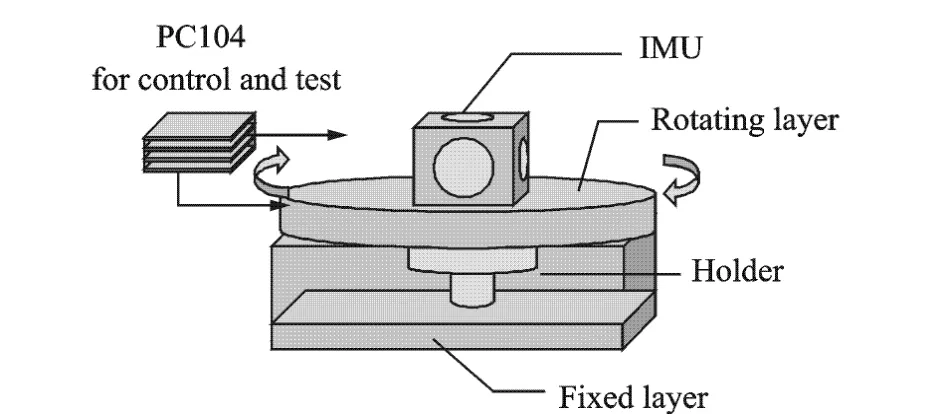
Fig.1 Structure of rotating SINS
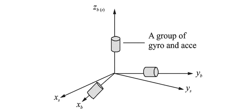
Fig.2 Rotating coordinate

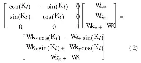

The equivalent error of gyros and accelerometers on b-axis is respectively shown as follows Wkb=Cbs W ks=where Wk is the gyro error,W f the accelerometer error,WK the error of rotating speed.By rotating,errors of x-axis and y-axis gyros are cosine modulated.According to the cyclical principle of cosine function,constant errors of x-axis and yax is are integrated to zero,so the impact of the inertial sensor error on SINS is reduced except the error of z-axis.In Eq.(2),WK is added to the output of z-axis gyro and diverged with time in the navigation process. The impact is critical when SINS works in a long-run time.
1.2 Modif ication of rotating SINS
The system error is accumulated when the whole IMU rotates,and z-gyro is suggested to be set on the fixed layer to avoid the rotating rate impaction.
Four related coordinates are first interpreted in the improved system: Gyro coordinate(g),containing horizontal x-gyro and y-gyro;Rotating coordinate(s);Fixed coordinate(f),containing vertical z-gyro;Body coordinate(b).Theoretically,zg,zs,zf,and zb are coincident mutually.
When the system works,error models of gyros and accelerometers are


Compared with Eq.(2),the z-gyro error in Eq.(4)is protected from impaction of rotating-remain error after compensation.
2 UN-COINCIDE COORDINATE ERRORSIN ROTATING SINS
Different from the theoretical rotating modulation analysis, the implementation is insufficient: Machine-processing errors are inevitable,any component has horizontal and vertical errors on the surface,and coordinates are imperfect superposition with each other.For g,s,f coordinates as instance,zg,zs and zf are not quite coincident due to mechanical installation errors in engineering implementation.The type of misalignment situations is various,and two main kinds of situation are taken into account for deep discussion.One situation is that zg and zs are not coincident.The other is that zsand zfare not coincident. Each kind restriction on rotating modulation impact is analyzed in details as follows.
2.1 Misalignment between zg and zs
Misalignment between zg and zs means the coordinate where gyros are installed is not coincident with the rotating coordinate. The transformational relationship between g and s is referred to the Eulerian angle method.Assuming that Eulerian angles are T,U and V,when the system works,the transformation matrix is

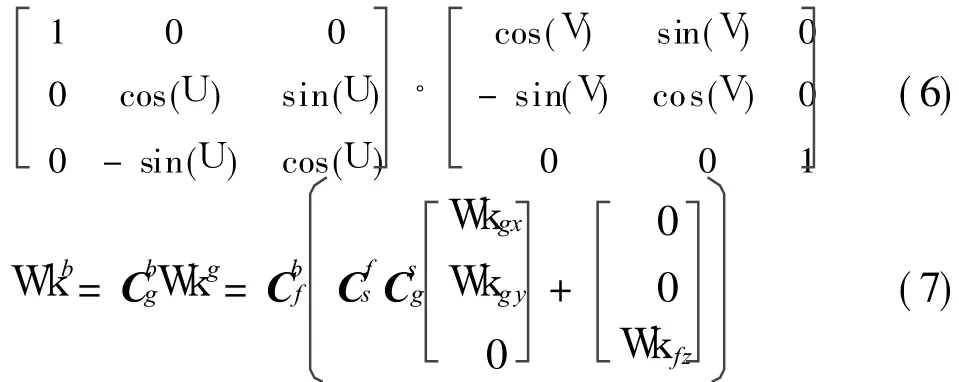
As the Eulerian angle T is quite small,the variable sin T can be considered as T and cos T can be considered as 1. Similarily,U and V are approximated by the same way.Besides,Cbfis set to I and physical quantities more than two-order are neglected,so Eq.(7)is further simplified as Wkb=

When angular velocity in Eq.(8) is integrated in a domain of timethe cumulative angular error is

From Eqs.(8,9),the horizontal and vertical equivalent errors of angular velocity are impacted by three gyros.Eq.(9)clearly shows that the extra errors on x-axes and y-axes are modulated by rotating manner;Errors on z-axis are not modulated,and the impact factors in z-axis error model include T,U,Wk gx,Wk gy,and Wk f z.
2.2 Misalignment between zs and zf
Misalignment between zs and zf means the rotating coordinate and the fixed coordinate are not coincident,the transformational relationship between s and f is considered,and the Eulerian angleis set as a,b,c.The transformation matrix is C fg=


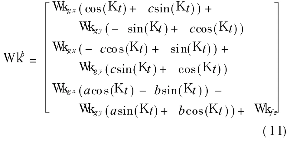
The cumulative angular error is

Eq.(11)shows that when misalignment between s and f exists,horizontal and vertical equivalent angle rate error models are complicated,but the horizontal modulation is not impacted.The extra error from x-and y-gyros is modulated by rotating process due to the misalignment structure.The modulation result is similar to the coincident situation,and the impact of misalignment between s and f do not lead to the extra error theoretically.
3 ANALYSISAND SIMULATION
3.1 Impact of misalignment between zg and zs
When the misalignment between zg and zs exists,the impact of z-axis error is caused by each gyro and misalignment angle.The relevant attitude and position errors due to z-axis equivalent error are set as follows
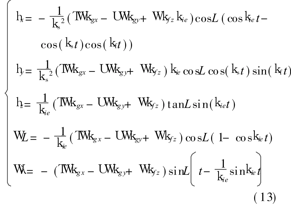
where k s is the Schuler frequency,k f the Foucault frequency[4].Eq(13)shows that the error is oscillated and the amplitude increases with the factors.Especially,the latitude error is a time function,and leads to the serious impact of ex tra error.
According to the attitude and position error equations,it is assumed that the gyro accuracy is 1°/h,and Aurelian angles are[1.2°,1.3°,1.5°].Then at the place of 20°north latitude,the stable values of each attitude and position errors are

The stable value intuitively illustrates that when tilt angle is about 1°,the misalignment leads to 0.001 orders of magnitude attitude error,and pitch error can beignored.The latitude error is 0.002°and equal to 180 m,and the longitude error gradually increases by time,which means that the misalignment may lead to serious impact on position property.
3.2 Simulation
As misalignment impact is related with the gyro accuracy,the tilt angleas well as the motion state,several kinds of simulations are performed.
First of all,different-level gyros are selected for simulating and analyzing the impact of misalignment between gyro coordinate and rotating coordinate.The relevant parameters are set as:
(1)For three gyros,a kind of gyro is 1°/h,another kind of gyro is 0.1°/h;
(2)For three accelerators,each bias and first-order Markov process are 5× 10⁻⁴g,scale factor error is 50×10-6,and installation error is 4″;
(3)For the obliquity error,the Eulerian angle is[1.2°,1.3°,1.5°],and rotating speed is 6°/s;
(4)Simulation time is 1 h,step length is 0.02 s,and the initial position is[110°,20°,500 m];
(5)The body is in static state.
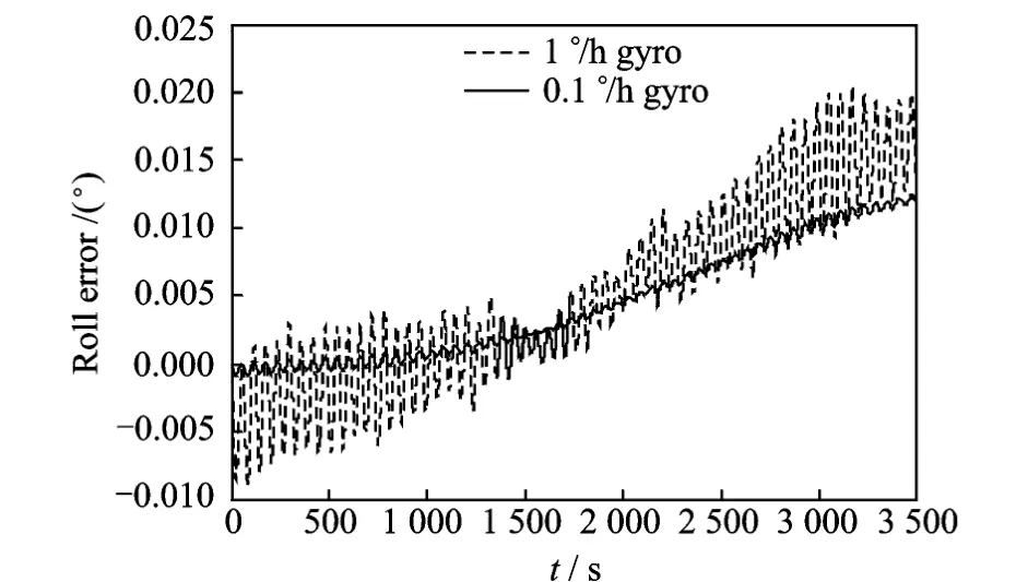
Fig.3 Roll error
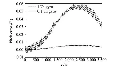
Fig.4 Pitch error
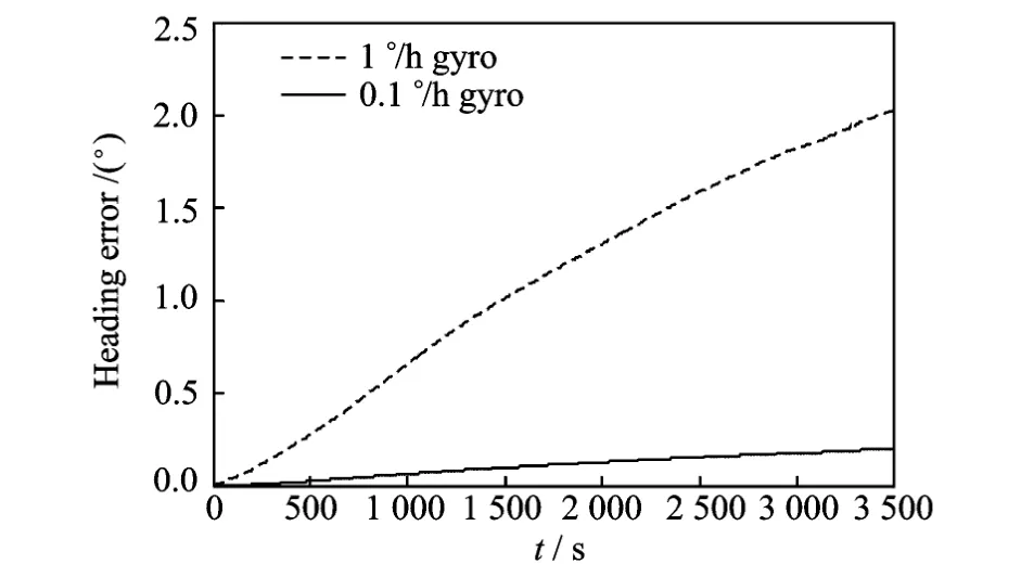
Fig.5 Heading error
Figs.3-6 are the simulation results about misalignment impact under the assumed condition,and the error is derived by comparing with the complete coincide-coordinated condition.Different from analysis in Eq.(13),attitude and position errors plotted in these figures are complete analysis and caused by the z-axis gyro error and the combined errors.
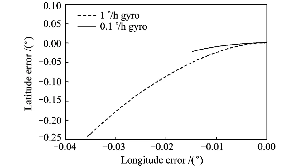
Fig.6 Longitude-latitude error
These plots show that when coordinate setting x-and y-gyros is not coincident with the rotating coordinate, the misalignment leads to attitude and position errors of about 0.01°.They also show that when low-accuracy gyro is used,the impact is much worse about an order of magnitude difference.
Secondly,many simulations are taken into account three motion states:Static motion,landmotion and air-motion.Similarly,the tilt angle is set as[1.2°,1.3°,1.5°],the gyro accuracy is 0.1°/h,other conditions are same as the former part.The land-motion includes 10 m/s uniform motion. The air-motion flight track includes pulling up at the speed of 2.5°/s,ascending at 1.5 m/s,turning roll-direction by 30°at the speed of 5°/s,low-head- 2.5°/s,reducing the level speed to-1.5 m/s,diving by-45°.The maximum values of system errors caused by misalignment are listed in Table 1 and simulated according to the motion state.
Compared with data on static state,SINS on active motion states is largely impacted,and the error value is orders of magnitude lager than that in static state.
On the land-motion state,the impact of heading error is significant changed,and about twice as much as that in air-motion state.Through a preliminary analysis,it is mainly because the land speed acts on the misalignment,and makes more serious impact.

Table 1 Maximum values of system errors (°)
On the air-motion state, the roll-pitch attitude and position are obvious changed,the combined factors lead to about 3°error of system error,and make the performance worse than that only in the state of misalignment.This order of magnitude system property is too poor to meet general navigation demand.
The above simulation results mean that misalignment between gyro coordinate and rotating coordinate can impact on SINS performance,and the impact cannot be neglected.Moreover,combining gyro accuracy with active motion state, the SINS error is non-linear changed and the system property is greatly impacted.
3.3 Solution and compensation
From Eq.(13),it is known that the main impact factors are constants caused by the tilt angular and the gyro error. When another rotation is set,TWk gx-UWk gy+Wk fz can be modulated by cosine functions referring to the rotating modulation principle,the integration of the error factors is zero in a period,and major of the residual impact may be eliminated. The property of rotating SINS can be enhanced to a certain degree by double-axis rotation,when misalignment exists between zg and zs.component has horizontal and vertical errors on the surface,and the corresponding coordinates are not coincident with each other.To resolve the problem,two kinds of situations are discussed:One is misalignment between the gyro coordinate and the rotating coordinate; The other is misalignment between the rotating coordinate and the fixed coordinate. The error models of equivalent angle-rate and acceleration errors are built to calculate its impact on SINS accuracy.The analysis is taken to illustrate the impact on SINS performance when g and s coordinates are misaligned. Simulation results show that the system error is non-linear accumulated considering such parameters as the gyro accuracy and the motion states.
A double-axis rotation is suggested to reduce the error according to the rotating modulation principle. The further study will focus on the double-axis structure as it may introduce some other complicated process.
[1] Heckman D W,Baretela LT M. Improved affordability of high precision submarine inertial navigation by insertion of rapidly developing fiber optic gyro technology[C]∥2000 IEEE PLANS.San Diego,CA,USA:IEEE,2000:404-410.
[2] Ishibashi S,Aoki T,Yamamoto I,et al.The method to improve the performance of an inertial navigation system using a turntable [C]∥Proceedings of the Sixteenth(2006)International Offshore and Polar Engineering Conference.San Francisco,California,USA:International Society of Offshore and Polar Engineers,2006:229-232.
[3] Yuan Baolun. Research of rotating navigation system based on four mode differential laser gyro[D].Changsha:College of Opto-Electric Science and Engineering, University of Defense Technology,2009.(in Chinese)
[4] Zhang Ling,Liu Jianye,Lai Jizhou.Rotating fiber optic gyro strap-down inertial navigation system with three rotating axes[J].Transactions of Nanjing University of Aeronautics &Astronautics,2008,25(4):289-294.
[5] Nie Qi,Gao Xiaoying,Liu Zhun.Research on accuracy improvement of INS with continuous rotation[C]∥ Proceedings of the 2009 IEEE International Conference on Information and
4 CONCLUSION
The rotating technology modulates the gyro and the accelerator errors on SINS,improves the SINS performance,and reduces the accuracy requirement of gyros and accelerators. As the modulation technology is insufficient,it has unmodulated and error-accumulating problems.This paper studies the rotating principle,makes modification on the rotating structure, and proposes an improved mehtod by setting unmodulated gyro on the fixed layer.Analysis shows the method can effectively avoid the error-accumulating problem.
However,the rotating technology adds the rotating structure,and changes the single fixed IMU in SINSinto two parts:Rotating layer and fixed layer.This introduces a new problem:Each Automation.Zhuhai,China:[s.n.],2009:870-874.
[6] Zhang Lundong,Lian Junxiang,Wu Meiping,et al.Research on auto compensation technique of strapdown inertial navigation system[C]∥2009 International Asia Conference on In formatiocs in Control,Automation and Robotics.Washington,DC,USA:IEEE Computer Society,2009:350-353.(in Chinese)
[7] Zhang Zhixin,Zheng Chunlei. The technology of circumgyratetion modutate for the marine FOG inertial navigation system[C]∥Sixth Annual Conference of Inertial Technology. Ningbo,China:Chinese Society of Inertial Technology,2008:86-90.(in Chinese)
[8] Liu Jianye,Zhao Wei,Xiong Zhi,et al.Principle and application of navigation system[M].Xi′an:Northwestern Polytechnic University Press,2010:87-118.(in Chinese)
 Transactions of Nanjing University of Aeronautics and Astronautics2011年2期
- Transactions of Nanjing University of Aeronautics and Astronautics的其它文章
- PHENOLIC ANTIOXIDANTS DETERMINATION IN FOOD ITEMS USING REVERSED-PHASE HPLC
- APPROXIMATION OF INTERVAL BEZIER SURFACES
- STUDY ON OPTIMIZATION OF HIGH PERFORMANCE CONCRETE ADMIXTURES
- SI-INSPIRED ENERGY AWARE QoSROUTING TREE FOR WSN
- NOVEL APPROACH TO LOCATOR LAYOUT OPTIMIZATION BASED ON GENETIC ALGORITHM
- COMPENSATION CONTROL OF REAL-TIME UNBALANCE FORCE FOR ACTIVE MAGNETIC BEARING SYSTEM
