Analysis and Optimization on Factors Affecting Forming Quality of Half Axle Gears Warm Precision Forging
WANG Menghan , CHEN Xihou, and ZHOU Jie
1 College of Material Science and Engineering, Chongqing University, Chongqing 400044, China
2 School of Electronic Information and Automation, Chongqing University of Technology, Chongqing 400050, China
1 Introduction
Precision forging is defined as a flashless near net-shape forging operation which generates high quality parts concerning surface quality and dimensional accuracy.Nowadays, its application in gears manufacture becomes more and more popular. Some successes have been made in Germany, America and Japan, etc. In Germany, spur gears with tolerance up to rank 7 and great intensity have been forged by cold precision forging technology[1]. In Japan, CHITKARA[2]developed a special die-set for hot forging of bevel gears used on single action hydraulic press. Because of the large number and variety of factors having an influence on precision forging the process is very difficult to analyze. Therefore a whole range of computer tools are used for the analysis and optimization of the forging process[3]. HUNG[4], proposed a mathematical model using an upper bound method for precision forging of spur gear forms and spline to investigate the plastic deformation behavior of billet within the die cavity. YANG, et al[5], carried out a finite element method(FEM) simulation of the isothermal precision forging of a blade with a damper platform. DOEGE, et al[6],developed an advanced finite element(FE) simulation model to meet the specific requirements of precision forging processes modeling for increasing the accuracy of the results.In the model a new friction and a new heat transfer law are developed. Although the above references were all focusing on the simulation and the analysis of the precision forging process, they have not proposed a concrete method to evaluate and optimize the forming quality.
In this paper, a special die-set for enclosed-die forging of half axle gears used on double action hydraulic press was proposed. The finite element analysis(FEA) software DEFORM_3D is used to investigate the warm precision forging process. The main factors affecting gears forming quality were analyzed and optimized to control the forming quality. An evaluation method, included three figures, was proposed as the basis of the optimization. At first, a precision forging process of half axle gear was developed to replace the traditional forming process. This new process can increase the stock utilization, improve the product geometric precision, and reduce the energy consumption.And then the forming process was simulated and analyzed by using FEM. The die structure, web thickness and web position were found as the main influential factors of the precision forming quality. The affecting is revealed in three figures. They are maximal forming load, material fill rate and maximal damage factor. So an investigation of the relationships between three influential factors and three forming quality figures had been taken. The details and the results had been shown in section 3. Lastly, some conclusions had been drawn.
2 Precision Forging Process Development
Fig. 1 shows the half axle gear sketch and forging piece model. The traditional forging process of half axle gears is as follows: heating, blocking, preforging, trimming, scale removal, heating, finish forging, trimming, surface cleaning, cold sizing, machining inner hole, half axle and big-end surface, broaching spline, heat treatment, grinding inner hole, and shot blasting[7–9].
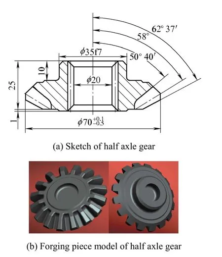
Fig. 1. Half axle gear sketch and forging piece model
As far as the former process is concerned, the energy consumption is excessive, the stock utilization and the work efficiency are also lower. To solve these problems, a warm precision forging process without flash was developed using CAD/CAE technology, which is energysaving; material-saving and efficient.
The new process is listed as below: Low- or non-oxidized heating, enclosed-die forging, surface cleaning, machining inner hole, half axle and big-end surface, broaching spline, heat treatment, grinding inner hole, and shot blasting.
In contrast with the traditional process, the new process can reduce the energy consumption, increase the stock utilization up to 90.1%, shorten the flow and improve the average productivity.
3 Forming Process Simulation and Analysis
Two projects were made to research on the three factors which determine the forming effect of half axle gear. The process was optimized according to the factors such as die structure, web thickness and web position. Fig. 2 shows the die-set for precision forging of half axle gear used on double action hydraulic press. In the die-set two compensating rings with negative allowance were used to pre-stress the upper and lower cavity dies. By this means the elastic deformation of cavity dies can be compensated.
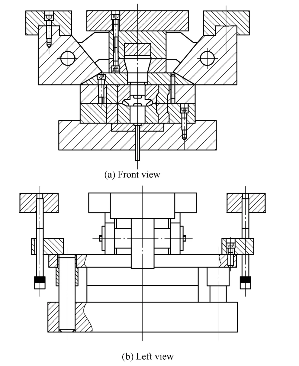
Fig. 2. Die-set for precision forging of half axle gear
3.1 FEM model
It is important to make certain the tooth dimensions of the die. Some factors must be taken into account, such as heat expansion, springback, scales of forging piece and die.Assuming that the temperature field of forging piece is equal to that of the finish forging die, their heat expansion should be equal and linear. Then the dimension of cavity can be ascertained according to the formula below:

where A —Equivalent weight linear-expansion ratio,
ε —Equivalent weight elastic strain.
The parameters of the FEM model are shown in Table.These simulations were performed by DEFORM-3D with rigid-plasticity FEM model[10]. The die should be rigid in the simulation. And the press velocity is 8 mm/s.

Table. Parameters of the FEM model
3.2 Effect of die structure on forming
It can be seen from Fig. 3 that the tip of gear teeth was formed finally. Project 1 was designed based on the traditional theory. In this project, both the bottom of upper punch and the top of lower punch are flat. The cavity with teeth is in the upper die, while the cavity with back-cone is in the lower die. The tooth tip of forging piece is blended.Simulation shown in Fig. 4 and Fig. 5 indicate that the tip corner in project 1 was not formed fully, and the load in that increased abruptly.

Fig. 3. Schematic diagrams of two projects
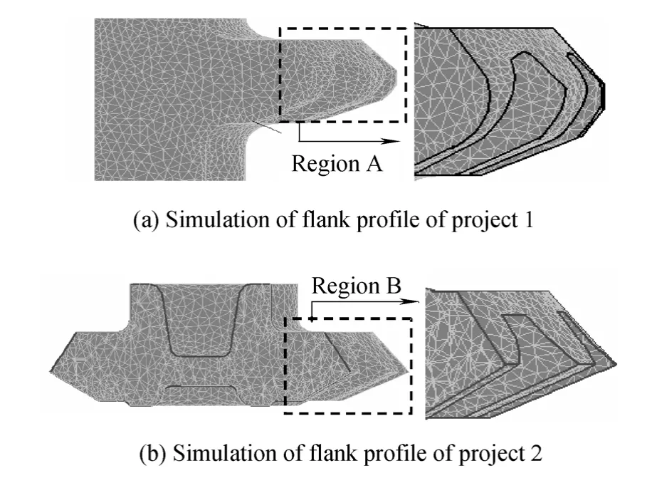
Fig. 4. Simulation of flank profiles in two projects
We improved the die set in project 2 on the punch shape and the cavity position. Both the bottom of upper punch and the top of lower punch were added with bosses. The cavity with teeth is in the lower die, while the cavity with back-cone is in the upper die. This structure helps to locate the rod billet. The tooth tip of forging piece is sharp-angled.Although a removal process is added, this change brings the advantage of containing redundant material and ensures the full filled flank profile. The bosses added can bring radial force to the billet, which helps the material flowing and improves the filling capability. Thus the flank profile is well-rounded and without failure. Fig. 4(b) shows the simulation of flank profile in project 2.

Fig. 5. Simulation of the forming load in two projects
As a result of friction between punch and billet, the maximal load relative to the project 1 was not obviously reduced, but the load curve change from abrupt to gradual.The stock utilization of project 2 relative to project 1 increased by 9.7 percent, and the man-hour of machining inner hole decreased. Fig. 5 shows the load-stroke curves contraction on two projects.
We conducted two experiments according to the same parameters of each simulation respectively to validate the simulations. Fig. 6 shows the results of the two experiments.It can be seen that the check bar in project 1 has not been filled up, while the check bar in project 2 has very clear profile and its teeth were well-rounded. The experiment fits well with the simulation.
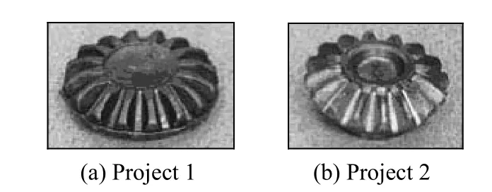
Fig. 6. Experimental results of two projects
3.3 Effect of web thickness and position on forming
3.3.1 Effect of different web thicknesses on forming
Fig. 7 is a sketch of web position and its thickness. In this figure, the web thickness is t, the distance between the web center and the end surface is h, the inner hole diameter is d,and the tooth depth is H. In this work, d is 20 mm, H is 15 mm, and h is 42 percent of H. Simulations were taken when the web thickness were 4 mm, 5 mm, 6 mm, 7 mm, 8 mm,and 9 mm, respectively. The forming load, metal filling rate,and material damage factor are investigated to evaluate the effect of different web thicknesses on forming.
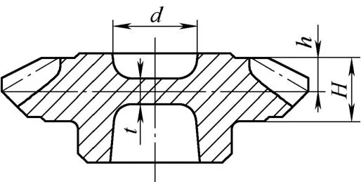
Fig. 7. Sketch of the web position and its thickness
Fig. 8 shows the influence of web thickness on maximal forming load. Fig. 9 shows the influence on material fill rate. And Fig. 10 shows the influence on maximal damage factor. Considering the above factors comprehensively, the best forming quality is achieved when t is 6 mm, about 30 percent of d.

Fig. 8. Influence of web thickness on maximal forming load
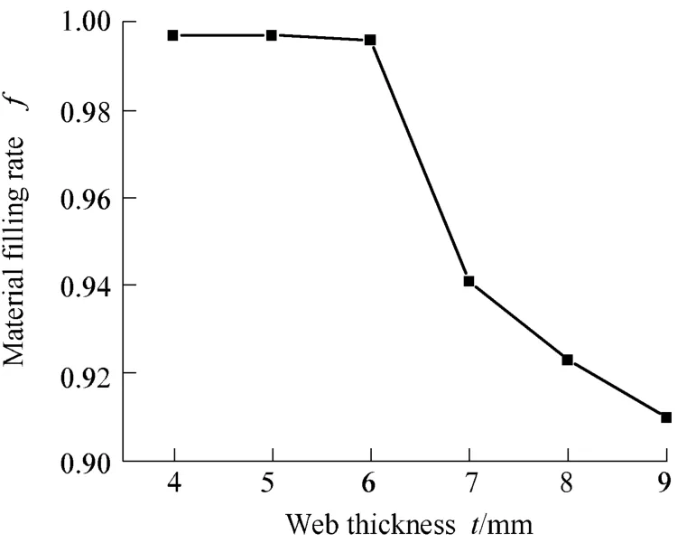
Fig. 9. Influence of web thickness on material filling rate

Fig. 10. Influence of web thickness on maximal damage factor
3.3.2 Effect of different web positions on forming
The web position will influence the forming quality, while the thickness of the web is fixed. Simulations were taken with different web positions. Fig. 11, Fig. 12 and Fig. 13 show the results on maximal forming load, material fill rate and maximal damage factor, respectively.
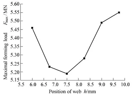
Fig. 11. Influence of web position on maximal forming load
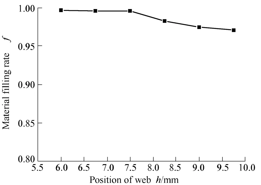
Fig. 12. Influence of web position on material fill rate
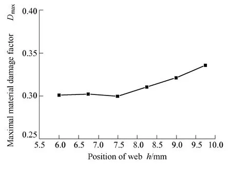
Fig. 13. Influence of web position on maximal material damage factor
When h is 60 percent of H, the metal flowing and filling is unsatisfactory, the material damage is serious, when h is 50 percent of H, the metal flowing and filling are easiest, the load is lowermost, and the material damage factor is minimum.
4 Conclusions
(1) The flank profile is difficult to be filled ultimately.In the phase when the gear tip is filled, the load rises rapidly.
(2) Both the bottom of upper punch and the top of lower punch are added with bosses, which brought radial force improving material filling capability.
(3) The sharp-angled tooth tip brings the advantage of containing redundant material and ensuring flank profile filled.
(4) When the thickness of the web was 30 percent of the inner hole diameter, and the web located at the middle plant of the gear, the forming quality is the best, and the load is lowermost.
[1] NEHER R. Cold forging of gears and profiles of couplings[C]//Proceedings of the International Conference on New Developments in Forging Technology, Fellbach, Stuttgart,Germen, May12–15, 1999: 305–311.
[2] CHITKARA N R. Near-net shape forging of spur gear forms: an analysis and some experiments[J]. International Journal of Mechanical Sciences, 1996, 38(9): 891–916.
[3] GRONOSTAJSKI Z, HAWRYLUK M. The main aspects of precision forging[J]. Archives of Civil & Mechanical Engineering,2008, 8(2): 39–55.
[4] HUNG Hsiou Hsu. A study on precision forging of spur gear forms and spline by the upper bound method[J]. International Journal of Mechanical Sciences, 2002, 44(8): 1 543–1 558.
[5] YANG He, ZHAN Mei, LIU Yuli. A 3D rigid–viscoplastic FEM simulation of the isothermal precision forging of a blade with a damper platform[J]. Journal of Materials Processing Technology,2002, 122(1): 45–51.
[6] DOEGE E, BEHRENS B A, SCHAEFER F. Simulation of phase transformation in hot forging dies during a precision forging process by means of finite-element-analysis[C]//Proceedings of the 8th International Conference on Numerical Methods in Industrial Forming Processes, Columbus, Ohio, USA, June 13–17, 2004:572–576.
[7] TIAN Fuxiang. Design and manufacture of die using in precision forging of bevel gear[J]. Manufacture of Die, 2002, 8(12): 28–33. (in Chinese)
[8] CHENG Yu, LI Gang, GUO Cheng, et al. Study on cold precision forging of spur gear forms[J] Forging Skill, 2003, 16(2): 11–12. (in Chinese)
[9] CHEN Xiaju. Metal precision forming processes[M]. Beijing: China Machine Press, 1999. (in Chinese)
[10] PENG Yinghong. Simulation technique of metal forming[M].Shanghai: Shanghai Jiao Tong University Press, 1999. (in Chinese)
 Chinese Journal of Mechanical Engineering2010年1期
- Chinese Journal of Mechanical Engineering的其它文章
- Contents and Abstracts of Journal of Mechanical Engineering ISSN 0577-6686, CN 11-2187/TH*
- Measurement of Attenuation of Ultrasonic Propagating through the Thin Layer Media with Time Delay Spectrum
- Effect of Air Injector on the Performance of an Air-lift for Conveying River Sand
- Innovation in the Computing System of Straightening Force
- Numerical Method Based on Compatible Manifold Element for Thin Plate Bending
- Investigation on Uniaxial Tensile Instability of USIBOR1500 Steel Sheets at Elevated Temperature
