Investigation on Uniaxial Tensile Instability of USIBOR1500 Steel Sheets at Elevated Temperature
MIN Junying, LIN Jianping, TIAN Haobin, SUN Guohua, and XU Zhou
1 College of Mechanical Engineering, Tongji University, Shanghai 201804, China
2 College of Mechanical and Electrical Engineering, Shanghai Second Polytechnic University, Shanghai 201209, China
1 Introduction
Mechanical properties and forming limits are especially important in hot forming of sheet metal, and the necking, as a typical phenomenon of the local deformation, is one of the indications of mechanical properties[1].
Since the steel is rate sensitive at elevated temperature,the investigations on the diffuse instability and localized instability of USIBOR1500 steel sheet under uniaxial tension at elevated temperature is significant. In the sheet forming process with stretch, the diffuse instability, namely the diffuse necking, first occurs and then the localized instability, namely the localized necking, occurs until fracture. Three forming limit curves(FLCs) can be obtained by regarding the diffuse instability, the localized instability and the fracture as limits respectively. The FLC from the diffuse instability is the lowest and safest, but the beginning of the diffuse instability is difficult to be determined in experiments. The FLC from the localized instability and the FLC form fracture are commonly used[2]. The difference between the FLCs from the localized instability and diffuse instability is relatively great for rate sensitive material, and the necking rate has a great influence on this difference.The lower the necking rate is, the greater the distance is.According to Ref. [3], the necking rate is a critical factor of the tensile stability and also directly affects the elongation.The necking rate was investigated earliest by HART[4],since then, more and more scholars have been interested in the research on the necking rate[5–7].
The investigation into the mechanical properties of the hot forming technology of USIBOR1500 ultrahigh strength steel has aroused the interest of many scholars, and there has been many reports about tensile tests of the steel at high temperature[8–10]. However, these investigations have not involved the necking behavior.
In the following sections, based on Inoue Kachiro’s flow stress constitutive model at elevated temperature, the relation is theoretically deduced between the diffuse necking rate along with localized necking rate and the exponent of strain rate sensitivity m together with the strain ratein the present study, and tensile tests of USIBOR1500 steel sheets at elevated temperature were performed on Gleeble3800. The necking behavior of the steel sheets is investigated at different temperatures and different strain rates. The distribution laws of the major strain of the specimens and uniform strain as well as necking widths will be also obtained from experiments.
2 Uniaxial Tensile Instability Analysis of USIBOR 1500 Steel Sheets
2.1 Theoretical analysis of instability
Inoue Kachiro used Eq. (1) to model theσ-ε relation of metals well at high temperature:

where σ is the true stress, ε is the true strain,is the strain rate, T is temperature, and k, n, m, β are material constants.
Since the process of plastic instability is finished quickly,namely, the temperature variation is very small during the plastic instability, here we suppose the temperature varies little, and T is a constant. Then Eq. (1) can be simplified as

Due to that the volume is unchanged in the plastic deformation, there is

where A is the cross-section area, and l is the length of the sheet metal.
After derivative to time of both sides of Eq. (3), we can obtain

According to true strain formula, there is
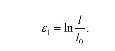

After insertion of Eq. (5) into Eq. (4), we can rewriteas

Assuming the cross-section area is A+Δ A at the necking place, where ΔA is a negative value, it can be obtained after differential of Eq. (6):

After differential of Eq. (2), we obtain

According to the condition of Swift’s diffuse instability[11], there is

After insertion of Eq. (9) into Eq. (8), we obtain

After insertion of Eq. (10) into Eq. (7), we can rewrite Eq. (7) as follows:

According to the theory of Hill’s localized instability[11],the hardening rate of the material equals the reduction rate of its thickness, there is the following expression:

where t is the thickness of the sheet metal, in uniaxial tensile due to

and then Eq. (12) can be expressed as

After insertion of Eq. (13) into Eq. (8), we obtain

Substituting Eq. (14) into Eq. (7), we can obtain

2.2 Discussion
According to HART’s rule[4], if the value of the cross-section area difference does not increase during deformation, namely, the necking rate is less than or equal to 0:

then the deformation is stable; when the diffuse instability occurs, namely the diffuse necking begins, the necking rate is greater than 0:
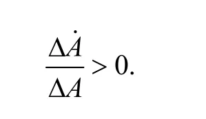
After insertion of Eq. (16) into Eq. (11), we can obtain the following equation:

where εDis just the uniform strain and the condition of the diffuse instability when it occurs. We can find out the relationship among the diffuse necking rate, m, n, andfrom Eq. (11). m has greater effect on the diffuse necking rate due to that m is less than 1, and the diffuse necking rate varies inversely with m but directly to the strain rate.
As the same, when the localized instability occurs, the expressionperforms as the localized necking rate.Substituting Eq. (16) into Eq. (15), we can obtain the following equation:

where εLis just the strain condition of the localized instability when it occurs. We also can find out the relationship among the localized necking rate, m, n, andfrom Eq. (15). m has greater effect to the localized necking rate due to that m is less than 1, and the localized necking rate varies inversely with m but directly to the strain rate.
3 Uniaxial Tensile Tests of USIBOR 1500 Steel Sheets at Elevated Temperature
3.1 Specimens
The sheet metal used in tests is USIBOR1500 steel sheets produced by Arcelor. Its chemical composition is shown in Table 1. Its thickness is 1.7 mm, and it also has rolling state. The dimensions of the specimens are shown in Fig. 1. Since the material USIBOR1500 exhibits no significant dependence on the rolling direction at elevated temperature, we only use the specimens whose length direction is in the rolling direction.
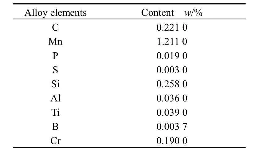
Table 1. Chemical composition of USIBOR 1500

Fig. 1. Sketch of specimen used in tests
3.2 Testing equipment
Gleeble3800 thermo-mechanical simulation system is chosen in tests.
3.3 Testing approach
Two thermocouples should be spot-welded to the middle of the specimens in advance. Then the specimens are fixed to the clamping apparatuses of the machine and the uniaxial hot tensile tests are to be carried out. The deformation is performed in isothermal conditions.
The testing temperature flow is: heating specimens to 900 ℃ with a cooling rate of 15 ℃/s, and preserving heat for about 5 min for soaking austenitization, then cooling the specimens to the testing temperature with 80 ℃/s and holding for 5 s, after that performing isothermal tensile tests till fracture, at last cooling fast to the room temperature. Since the bainite transference will occur below 650 ℃[12], the testing temperatures are respectively set as 700, 800, 900 ℃ and the material is in austenite state,where the specimens whose testing temperature is 900 ℃have no cooling after austenitization.
Then the width h of the specimens are measured from the break per 1 mm along the length direction, and the minor strain ε2can be calculated byand the major strain 1ε can also be calculated byin uniaxial tensile, where r is the coefficient of thickness anisotropy. Its value can be seen from Ref. [13]. Then we can obtain the major strain distribution of the specimens.
4 Results and Analysis
4.1 Stress-strain curves at elevated temperature
Fig. 2 shows the true stress-strain curves at different temperatures when strain rates are 0.02/s, 0.2/s, 1/s,respectively. We can obtain Table 2 by using of Inoue Kachiro’s flow stress constitutive model and the least squares.
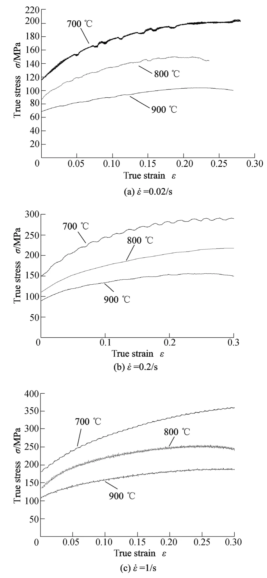
Fig. 2. Influence of the temperature on stress-strain curves at different strain rates
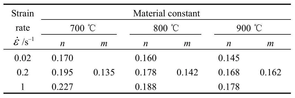
Table 2. Values n and m at different temperatures and strain rates
It can be seen from Table 2 how the temperature and the strain rate affect the value n and m. The value n decreases with the increasing of the temperature and the strain rate,but the value m increases.
4.2 Major strain distribution of specimens and analysis of the plastic instability
LI, et al[14], have theoretically elucidated that there is no absolutely uniform strain in uniaxial tensile in their investigation on the plastic instability. DU, et al[15], have described the necking deformation with two indexes of the limit strain and the necking width, where the necking width is determined as follows: given a small value θ, twice of xNcorresponding to the point, where the included angle of tangent and X-axis is θ, is the necking width, and εNis the uniform strain (see Fig. 3).
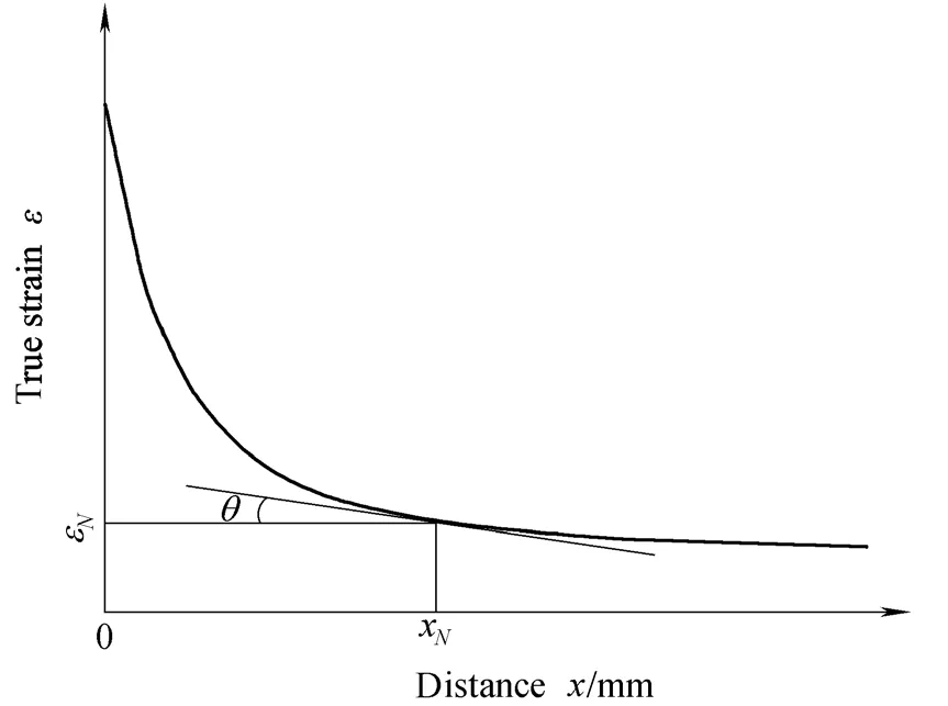
Fig. 3. Sketch of the major strain distribution
4.2.1 Influence of the temperature on the uniaxial tensile instability of the steel sheets
Fig. 4 shows the major strain distributions of specimens at different temperatures whenε˙equals to 0.2/s. According to the uniform strain of Eq. (17), inserting the value n and m in Table 2 into it, we can see that the values of the theoretically calculated uniform strains get well with the values measured from tests (see Fig. 5).
It can be seen from Figs. 4 and 5, when the strain rate is constant, the limit strain and necking width increase when the temperature increases, but the uniform strain decreases,where the necking width at 700 ℃, 800 ℃ and 900 ℃ are 14 mm, 18 mm and 28 mm, respectively, and we can see from specimen photos that the break is also narrow and thin.This is coincident with the results of theoretical analysis in the section 2.2, because according to Table 2, the value is greater when the temperature is higher, and the diffuse necking rate will be lower in accordance with Eq. (11). The deformation is more sufficient, and the necking region of the specimens is longer and narrower. The localized necking rate will be lower in accordance with Eq. (15), and the break of the specimens will be narrow and thin, and the rate of section shrinkage is greater.
4.2.2 Influence of the strain rate on the uniaxial tensile instability of the steel sheets
Fig. 6 shows the major strain distributions of specimens when the testing temperature is 800 ℃ and the strain rates are 0.02/s, 0.2/s, 1/s, respectively.

Fig. 4. Major strain distributions at different temperatures and the specimen photos
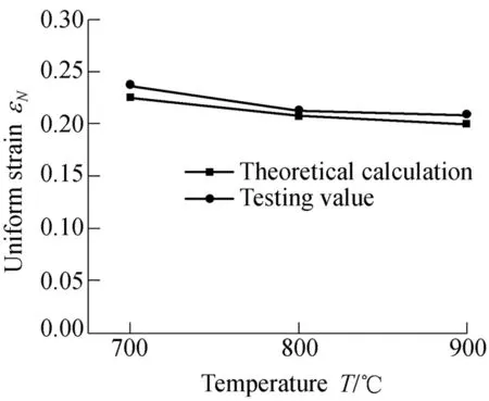
Fig. 5. Uniform strains of the theoretical calculations and measured values
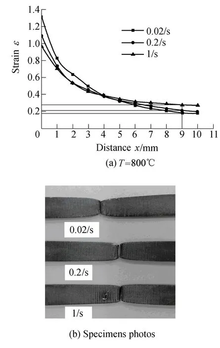
Fig. 6. Major strain distribution at different strain rates and specimen photos
Inserting the value n and m in Table 2 into Eq. (18), we can see that the values of the theoretically calculated uniform strain go well with the values measured from tests too (see Fig. 7).
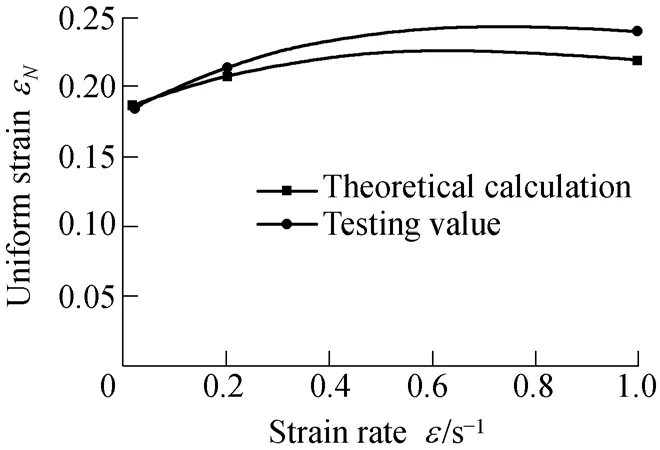
Fig. 7. Uniform strain of the theoretically calculations and measured values
It can be seen from Figs. 6 and 7, when the testing temperature is constant, the limit strain decreases with increasing of the strain rate, but the uniform strain increases,and we can see from specimen photos that the break is wide and thick. This is coincident with the results of the theoretical analysis in the section 2.2 too, because a greater strain rate is beneficial to the uniform deformation.According to Eq. (11), the diffuse necking rate will be greater and the necking region of the specimens becomes short and wide. The localized necking rate will be also greater in accordance with Eq. (15) and the break of the specimens, whose rate of section shrinkage is smaller, will be wide and thick.
5 Conclusions
(1) Based on Inoue Kachiro’s flow stress constitutive model at elevated temperature, combined with Swift’s diffuse instability rule and Hill’s localized instability rule,the relation is theoretically deduced between the diffuse necking rate along with the localized necking rate and the exponent of strain rate sensitivity m together with strain rateε˙of the USIBOR1500 steel sheets. It indicates that the diffuse and localized necking rates are in inverse relation to the exponent of strain rate sensitivity, but proportional to the strain rate;
(2) According to the time-temperature characteristics of hot stamping process, tensile tests of USIBOR1500 steel sheets were carried out on Gleeble3800, and the stress-strain curves were obtained in a strain rate range(0.2–1/s) and a temperature range (700–900 ℃). The values of the exponent of strain rate sensitivity and the hardening exponent in the corresponding test conditions were obtained through fitting the curves by least squares.
(3) The distribution laws of the major strain of the specimens and the uniform strains as well as the necking widths were also obtained, when the strain rate is 0.2/s but the temperature range is 700–900 ℃ and when the temperature is 800 ℃ while the range of ε˙ is 0.02–1/s.The theoretically calculated uniform strains go well with the values measured from tests.
(4) According to the two indexes describing the necking deformation raised by DU, et al, the limit strain and the necking width, as well as the characteristic of the break, the testing results indicate that, when the strain rate is constant,the limit strain and the necking width increase with the temperature, but the uniform strain decreases, and the rate of section shrinkage is greater; when the temperature is unchanged, the uniform strain increases with the strain rate,but the limit strain and the rate of section shrinkage reduce.
[1] WANG Xuebin, YANG Mei, PAN Yishan. Analysis of necking under condition of uniaxial tension of low-carbon steel specimen based on gradient-dependent plasticity[J]. Journal of Plasticity Engineering, 2002, 9(3): 55–57. (in Chinese)
[2] SUO Zhonglin. Mechanical analysis on necking diffusion in uper plastic tension deformation[J]. Journal of Changchun University of Science and Technology (National Science Edtion), 2006, 29(2):118–120. (in Chinese)
[3] LIANG Bingwen, CHEN Xiaodai, WANG Zhiheng. Forming properties of sheet metal[M]. Beijing: China Machine Press, 1996. (in Chinese)
[4] HART E W. Theory of the tensile test[J]. Acta Metallurgic, 1967, 15:351–355.
[5] HUANG Z Q, LEE L. Dynamic necking of an elastic-plastic cylinder under uniaxial stretching[J]. Inter. Journal of Solids and Structures, 1984, 20: 897–909.
[6] JOUVE D. Dynamic plastic necking instabilities for a biaxially puled plate[C]//Proceedings of the 8th International Conference on Mechanical and Physical Behaviour of Materials under Dynamic Loading, EURODYMAT 2006, Dijon, France, Sep. 11–14, 2006:251–256.
[7] HITOSHI M. Criterion and mode of the forming limit in sheet forming[J]. Journal of Material Processing Technology, 1992, 31(3):363–378.
[8] MERKLEIN M, LECHLER J, GEIGER M. Characterization of the flow properties of the quenchenable ultra high strength steel 22MnB5[J]. CIRP Annals-Manufacturing Technology, 2006, 55(1):229–232.
[9] NADERI M, BLECK W. An investigation into martensitic transformation in hot stamping process[J]. Computational Methods and Experiments in Materials Characterization III, WIT Transactions on Engineering Sciences, 2007, 57: 95–104.
[10] TURETTA A, BRUSCHI S, GHIOTTI A. Investigation of 22MnB5 formability in hot stamping operations[J]. Journal of Material Processing Technology, 2006, 177(1–3): 396–400.
[11] HU Shiguang, CHEN Hezheng. Engineering analytic of sheet metal forming[M]. Beijing: Beijing University of Aeronautics and Astronautics Press, 2004. (in Chinese)
[12] BERND-ARNO B, PHILLIPP O. Consideration of phase transformations in numerical simulation of press hardening[J]. Steel Research International, 2007, 78(10–11): 784–790.
[13] MERKLEIN M, LECHLER J, GODEl V, et al. Mechanical properties and plastic anisotropy of the quenchenable high strength steel 22MnB5 at elevated temperatures[C]//Proceedings of the 12th International Conference on Sheet Metal, Palermo, Italy, Apr. 1–4,2007: 79–86.
[14] SUOBEN, CUI Lingjiang, YU Lianzhong, et al. A study on the plastic instability in uniaxial tesion of sheet metal[J]. Forging &Stamping Technology, 1989, 1: 15–19. (in Chinese)
[15] DU Song, HU Shiguang. Construction of equilibrium equation and determination of uniaxial tensile strain distribution[J]. Forging &Stamping Technology, 1987, 4: 2–8. (in Chinese)
 Chinese Journal of Mechanical Engineering2010年1期
- Chinese Journal of Mechanical Engineering的其它文章
- Contents and Abstracts of Journal of Mechanical Engineering ISSN 0577-6686, CN 11-2187/TH*
- Measurement of Attenuation of Ultrasonic Propagating through the Thin Layer Media with Time Delay Spectrum
- Effect of Air Injector on the Performance of an Air-lift for Conveying River Sand
- Analysis and Optimization on Factors Affecting Forming Quality of Half Axle Gears Warm Precision Forging
- Innovation in the Computing System of Straightening Force
- Numerical Method Based on Compatible Manifold Element for Thin Plate Bending
