Numerical Method Based on Compatible Manifold Element for Thin Plate Bending
ZHANG Zhengrong *, ZHANG Xiangwei, and Lü Wenge
1 Faculty of Materials and Energy, Guangdong University of Technology, Guangzhou 510006, China
2 Faculty of Electromechanical Engineering, Guangdong University of Technology, Guangzhou 510006, China
1 Introduction
In thin plate bending FEM analysis based on Kirchhoff assumptions, the typical quadrangular and triangular elements are incompatible elements for discontinuous rotations on element boundary. These elements can pass the patch test, but the lower/upper bound of numerical solutions obtained from the elements can not be estimated for the nonmonotonic convergence, and it will affect computational accuracy and limit application range[1], so some methods have been proposed to construct compatible elements. FRAEIJS[2]presented a scheme to build conforming finite element for plate bending by increasing nodes on the boundaries or in element, and the degrees of freedom(DOFs) of internal nodes were eliminated through static condensation method to reduce the computational cost. MORLEY[3], et al, developed a conforming triangular element by the way of adhesive correction functions, which had cubically varying normal displacements along the sides and employed rational functions to supplement the ten term cubic description of the displaced surface. The mid-side connections were eliminated by means of extended interpolation and explicit ‘best’ linear approximations were derived for the final valuation of the element bending moments. NORMAN, et al[4], developed a complete conforming finite elements by the use of nodal variables of arbitrary polynomial order. PITACCO[5]proposed a compatible plate bending element by means of orthogonal polynomials expansion of the curvature field depending only on the element boundary traces. All the above fully conforming elements have very complicated calculation process and high computational cost, and the additional constraints imposed on the elements will make the structure too stiff, so it will affect computational accuracy and even probably cause worse results. Some generalized conforming finite elements, which can improve the computational accuracy, have been introduced on the basis of the discrete Kirchhoff assumptions or the weak conforming conditions[6–8], but these elements are not fully conforming finite elements, their convergence rate for displacement is not totally satisfactory. So it is very meaning for thin plate bending analysis to propose a numerical method based on fully compatible element without any additional constraints.
Numerical manifold method(NMM) is a more generalized numerical method than finite element method(FEM). The method performs numerical computation with finite element cover system, which is composed of two independent cover grids: mathematical cover grid and physical cover grid. Mathematical covers define the accuracy of approximate solution, and physical covers determine the solution domain[9–11]. Manifold method unifies finite element method with analysis method through finite cover system. By the use of high order cover functions and cover weight functions, it can construct high order continuous computational elements[12–14], and develop a high efficient and accurate numerical method for mathematical physics equations. The method has been successfully applied in some complicated engineering problems, such as numerical simulation of crack initiation and propagation, etc[15–17].
In this paper, the authors used NMM to solve thin plate bending problem, built a 16-cover high order conforming manifold element on standard rectangular cover system,derived manifold schemes for thin plate bending, and employed the analyses of square thin plate bending deformation to illustrate the adaptability and validity of the present manifold element.
2 Cover System of NMM for Thin Plate Bending
According to elastic theory, bending deformation of thin plate can be described only by the transverse displacement distribution on middle plane of the plate[18]. So, it is feasible just taking the transverse displacement as the basic parameter in NMM analysis.
Standard rectangular is introduced as mathematical mesh to form finite element cover system in manifold analysis of thin plate bending. In order to ensure compatibility, the transverse displacement on the boundaries and in element should be C1continuous. If 4-cover rectangular element as shown in Fig. 1(a) is employed to form finite element cover system in manifold method, it can not guarantee the continuity of rotations on the boundaries of element because element cover weight functions are polynomials not including full second order terms just like in FEM. So based on theory of manifold method, it is necessary for element compatibility to increase cover number of manifold element.
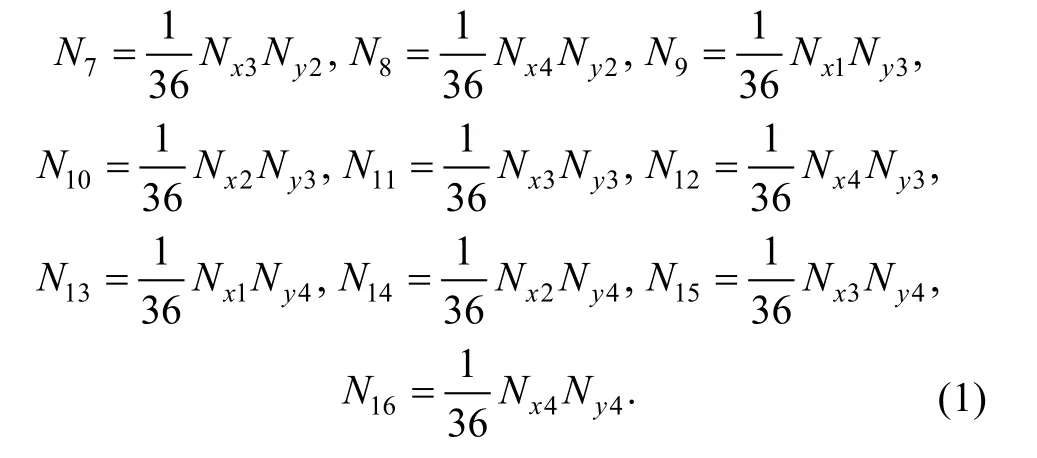
16-cover manifold element with the center coordinate(x0, y0) and the side length 2a×2b as shown in Fig. 1(b) is applied in this paper. Every manifold element consists of 16 covers around it. Element cover weight functions can be defined in the same way as B-spline surface construction[19],and expressed as follows:

Where
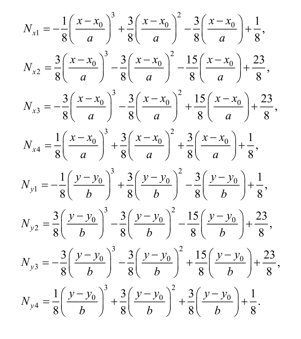
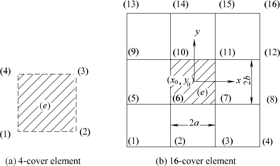
Fig. 1. Element for thin plate bending analysis
The transverse displacement cover function of every element cover can employ the form of polynomial, and stated as

which can be denoted for short as


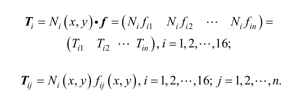
where
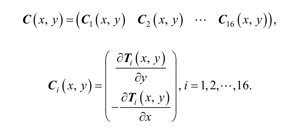
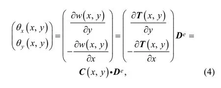
If the displacement function of every element cover is known, the displacement and rotations distribution in element can be obtained by Eq. (3) and Eq. (4).
3 Element Matrix
3.1 Matrixes of strain and stress
According to Kirchhoff assumptions of thin plate bending[18], the strain distribution in plate can be given by

where z is the distance to middle plane of the plate.are the curvatures of deflection surface along x and y direction.is the torsional rate. Substituting Eq. (3)into Eq. (5), we can yield
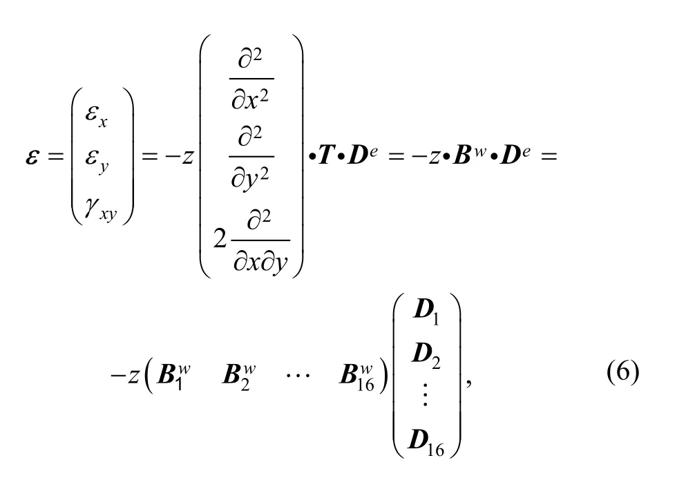
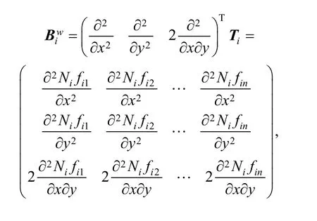
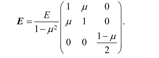
Stress can be calculated from strain by generalized Hooker’s law, i.e.,
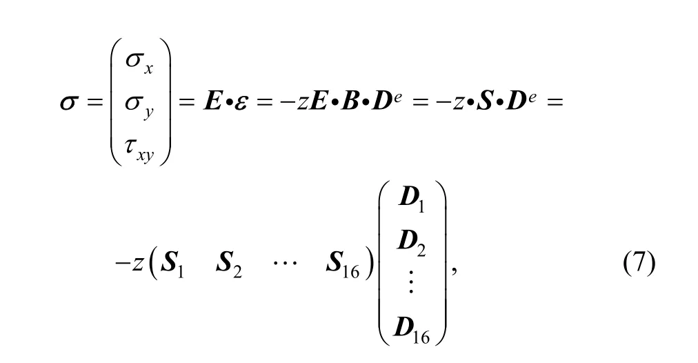
where S is the stress matrix, andis the stress submatrix; E is the elastic matrix which can be expressed as
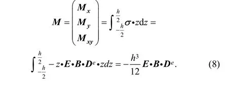
By the distribution of stress along thickness direction of plate, the bending moment M can be defined as
3.2 Finite element balanced equation based on manifold method
Balanced equation in manifold method can also be derived from minimum potential energy principle as in FEM[10–11,14]. On the assumption that there are M manifold elements and m physical covers in solved domain, and every cover has n unknown DOF variables, then the global potential energy Π generated from thin plate bending deformation can be expressed as
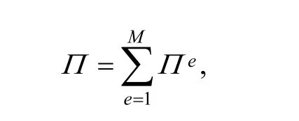

where the first term on the right side of Eq. (9) is the bending deformation potential energy, the second term Ceincludes potential energies generated from external forces,boundary constraints, and so on. Every term in Eq. (9) can be calculated in the same way as in FEM. Then from first order variation of element potential energy being equal to zero, element balanced equation can be derived as follows:

and ke·De=Fefor short. Where keis the element stiffness matrix; Feis the element load vector; Deis the element DOF variable vector. As every cover has n DOFs,submatrix ki,j(i, j=1, 2,···,16) in Eq. (10) is a matrix of size n×n, Di(i=1, 2, ···,16) and Fi(i=1, 2, ···,16) are submatrixes of size n×1. Diis the DOF variable vector of physical cover Ui. Fidenotes the load vector imposed on cover Ui.
Element potential energy includes elastic deformation potential energy and other potential energies. So element matrix and vectors in Eq. (10) consists of all parts of element matrixes and vectors derived from differential of relevant potential energies. Those are element stiffness matrix, load matrix, fix point matrix, and so on.
3.3 Element stiffness matrix
In manifold element (e), potential energy generated from elastic deformation of thin plate-bending is
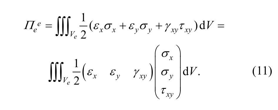
Substituting Eq. (6) and Eq. (7) into Eq. (11), we can yield
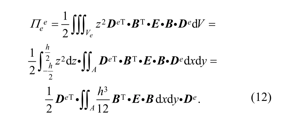
So, element stiffness matrix can be obtained from differential of potential energy Eq. (12) as follows:
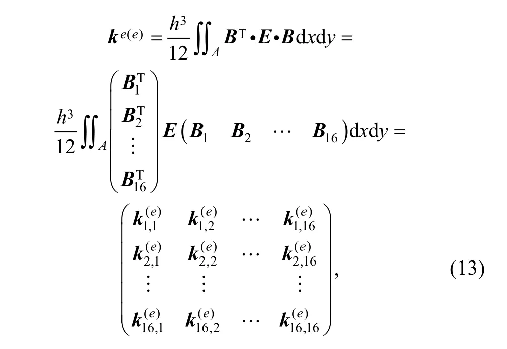
where stiffness submatrix can be expressed as

3.4 Load matrix
In thin plate-bending deformation, several kinds of loads can be imposed on the plate, which include transverse concentrated force, distributed transverse surface force,distributed transverse linear force and bending moment.According to finite element cover in manifold method,these loads should be transferred on to the DOF variables of every cover respectively.
3.4.1 Point load matrix
Supposing that transverse concentrated force Fzis loaded on the pointin element (e), and the transverse displacement of the point isPotential energy generated from the concentrated force can be defined as

3.4.2 Linear load matrix
Assuming that distributed transverse pressure pzis loaded on curve Γ in element (e), potential energy from the distributed load is

3.4.3 Surface load matrix
Presuming that distributed transverse surface pressure gzis loaded on element (e), and then potential energy from the distributed surface load can be expressed as

3.4.4 Bending load matrix
Granted that bending momentis loaded on curve Γ in element (e), and then potential energy from bending load is Substituting Eq. (4) into Eq. (17), we can obtain


So, load vector

can be defined as bending load vector.
3.5 Fixed boundary matrix
In FEM, the displacement boundary conditions can only be imposed on nodes and implemented by means of assigning large number, and so on. But in NMM, the displacement boundary conditions can be imposed on any point in element and the basic unknown variables is the cover DOF variables instead of physical variables on the nodes, so it should be implemented with other mathematical methods unlike in FEM, such as penalty function method. While penalty function method is applied in NMM, it assumes that there is a series of springs with high stiffness fixed on the boundary, known displacements are assigned to initial displacement of the springs, and boundary conditions can be implemented by variation of the spring deformation potential energy. There are two kinds of boundary conditions in thin plate bending deformation: known transverse displacement and known rotation. They need to be treated respectively.
3.5.1 Fix boundary matrix for transverse displacement
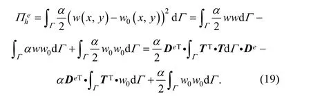
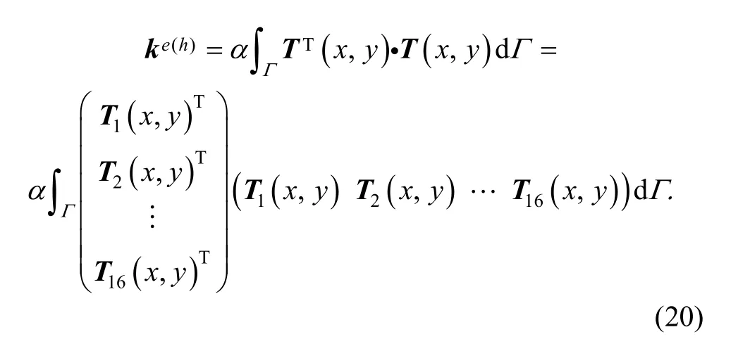
So, differentiating the deformation energy will get where ke(h)is a part of stiffness matrix, called fix boundary stiffness matrix for transverse displacement. The stiffness submatrix is

3.5.2 Fix boundary matrix for rotation displacement
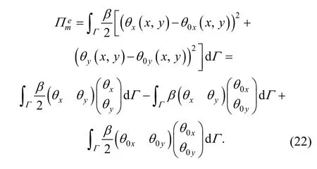
Substituting Eq. (4) into Eq. (22), we can yield

Differentiating the deformation energy, we will obtain

where ke(m)is a part of stiffness matrix, called fix boundary stiffness matrix for rotation displacement, and the stiffness submatrix is

and

is a part of load vector, called fix boundary load vector for rotation displacement.
3.6 Integration of element matrixes
Global balanced equation can be integrated by all the element balanced equations as follows:

where K is the global stiffness matrix; F is the global load vector; D is the global DOF variable vector.
Global stiffness matrix K and global load vector F are obtained by integrating element matrixes and vectors in the way as follows:

Element stiffness matrix can be obtained by
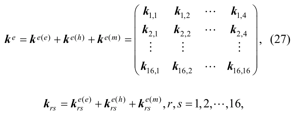
and element load vector is

Global balanced Eq. (26) can be solved as global matrix K and F are known, DOF variables and transverse displacement function of every cover can be obtained, and then all field variables distribution in whole region, such as transverse displacement, rotations, curvature, strain and stress can be acquired.
4 Analysis of Element Completeness and Compatibility
Through increasing cover number, high order continuous manifold elements can be constructed. 16-cover manifold element for thin plate-bending can ensure continuous transverse displacement and rotations inside element and on element boundaries, so it is a kind of compatible element meeting completeness requirements.
In 16-cover element (e) as showed in Fig. 1(b), the element cover weight functionis a complete cubic polynomial, while every displacement cover functionis a kind of continuous function with constant term, such as a polynomial, the global element displacement function

can express the deformation model of rigid displacement and constant strain. So it meets completeness requirements.
On the basis of thin plate bending deformation theory,when Ni(x , y ) is a complete cubic polynomial and wi(x, y )is a C1continuous function, it is obvious that transverse displacement w( x , y) and rotations θx, θyare continuous inside element. If it can be proved that transverse displacement and rotations are continuous on element boundaries, then we can draw a conclusion that the element meets compatibility requirements.
With regard to two adjacent elements as shown in Fig. 2,manifold element (e1) consists of cover (1)–(16), and element (e2) consists of cover (5)–(20), and edge (10) –(11)is the public boundary along y direction.
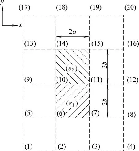
Fig. 2. Two adjacent elements
In element (e1), there existson edge(10)–(11), it can be deduced from the cover weight function Eq. (1) that

So the weight function of every cover in element (e1)should be as follows:
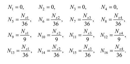
In element (e2), there exists, and then

So the weight function of every cover is as follows:
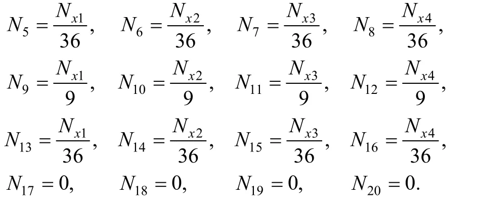
Coordinate x0of center point is the same value in both element (e1) and (e2), soand Nx4are also corresponding equal on public boundary. In both elements,the displacement cover function on public boundary is composed of the same covers, and the weight function of every cover is also coincident, so the global transverse displacement on public boundary should be also equal, that is
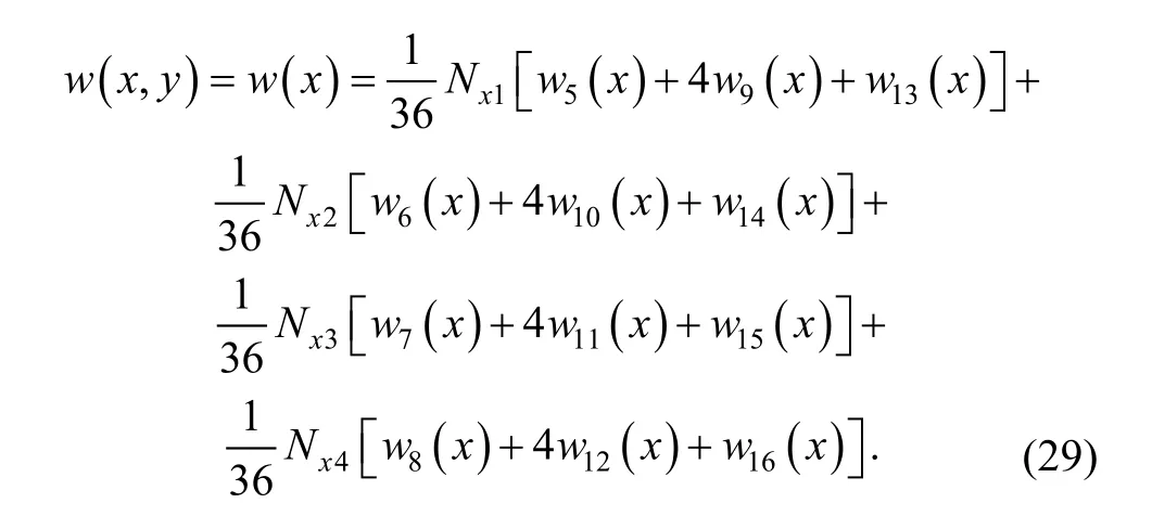
Eq. (29) means that the displacement is continuous on public boundary (10)–(11). It can be proved in the same way that the displacement is also continuous on other boundaries.
As to the rotation θyin manifold element, there exists


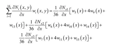

It can get the same result in element (e2). Sinceare the complete cubic polynomials andare continuous,is obviously continuous on public boundary (10)–(11). So it can be seen from above thatyθ is continuous on public boundary (10)–(11).
As regards to rotation θx, there exists


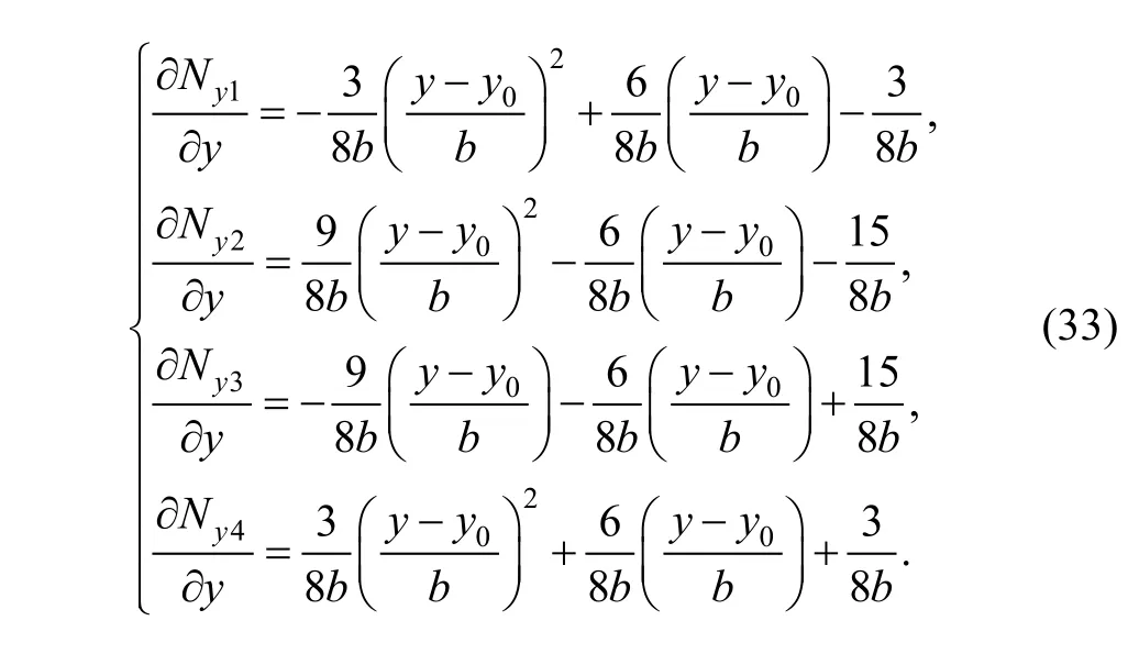
As to boundary (10)–(11) in element (e1), substitutinginto Eq. (33), we can obtain

and then the second term on the right side of Eq. (32) can be simplified as

In element (e2), there exists on boundary (10)–(11) that

We can draw a conclusion from the above analyses that 16-cover manifold element is a kind of fully compatible element, as the displacement w( x, y), rotations θxand θyall are continuous on the boundaries and inside the element. A deep study shows that not only θxand θyare continuous,but also w( x, y) is C2continuous, when the cover weight function adopt the form of Eq. (1) and the transverse displacement cover function of every coveris C1continuous, so the curvature of deflection surface is also continuous.
5 Application Examples
In this paper, some cases of thin plate bending deformation under different loads and boundary conditions are comparatively analyzed by NMM and FEM. The part for analyses is a square thin plate as shown in Fig. 3, with length L=20 mm and thickness t=1 mm. Material properties of the part are elastic modulus E=210 GPa and Poisson ratio μ=0.3. There are two kinds of loads: uniform load p=1 MPa on plate and concentrated load F=4 N on the center point of plate, and three sorts of boundary conditions: four clamped edges, four simply supported edges and four supported corner points. Considering symmetry, a shadow quarter of the plate is chosen as the analysis region.Numerical manifold analyses are implemented by programming in Matlab, finite element analyses are completed by adopting four-node shell element 63 inclusive only bending in program ANSYS.
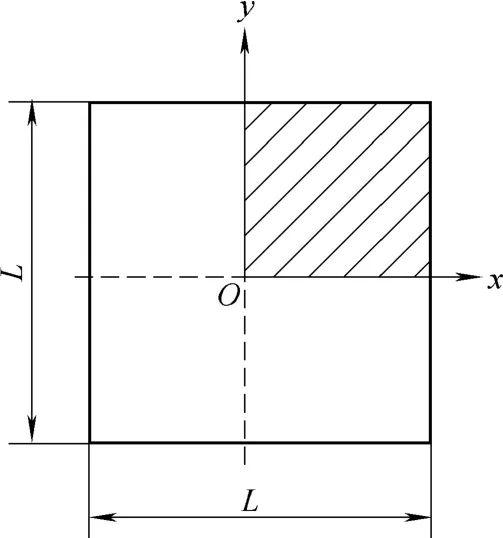
Fig. 3. Square thin plate
The maximum transverse displacements under different loads and boundary constraint conditions, which are the deflections at the center point of plate, are calculated out by NMM and FEM with different number and size of elements. The results are listed in Tables 1–3.

Table 1. Maximum deflections of the plate with four clamped edges

Table 2. Maximum deflections of the plate with four simply-supported edges
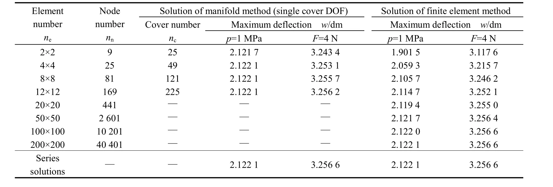
Table 3. Maximum deflections of the plate with four supported corner points
In NMM solutions, while adopting single DOF element cover (namely, the basic series f=(1)), the manifold element can satisfy completeness and compatibility requirements.High accurate solutions can be obtained by using 4×4 elements under all different conditions. The accuracy can be improved by taking 8×8 elements, and the results are approximately equal to these of series solutions. When adopting three DOF element cover (namely, the basic series f=(1 x–xiy–yi), where xi, yiare the center point coordinates of cover Ui), the element can also meet completeness and compatibility requirements. It can make further improvement on computational accuracy for increase of the displacement function order inside element,and the results from 4×4 elements are approximately equal
to these of series solutions. The same results can be obtained by FEM, but it needs to use about 100×100 or more elements in the calculation. It shows that NMM with compatible element, compared with FEM with four-node element, can improve accuracy and convergence greatly.
6 Conclusions
(1) In order to overcome the defects of incompatible four-node thin plate element in FEM, numerical manifold method was applied to analyze thin plate bending deformation based on Kirchhoff assumptions.
(2) 16-cover manifold element for thin plate bending was constructed on standard rectangular cover system, in which the weight functions of element covers were defined by the way like B-spline surface construction.
(3) All element matrixes for 16-cover element were derived on base of the minimum potential energy principle,and penalty function method was applied to implement displacement boundary conditions. The present numerical manifold schemes are much simpler than FEM schemes for employing only the deflection cover DOF as the basic unknown variables.
(4) 16-cover manifold element was proved to meet the requirements of completeness and compatibility, so it is a kind of fully conforming element.
(5) Bending deformation of square thin plate has been comparatively analyzed by manifold method with 16-cover manifold element and FEM with four-node plate element.The results illustrate that numerical manifold method can improve accuracy and convergence greatly.
[1] ROBERT D Cook, DAVID S Malkus, MICHAEL E Plesha, et al.Concepts and applications of finite element analysis[M]. 4th ed.New York: John Wiley & Sons, 2001.
[2] FRAEIJS de Veubeke B. A conforming finite element for plate bending[J]. Int. J. of Solids Struct., 1968, 4(1): 95–108.
[3] MORLEY L S D, MERRIFIELD B C. On the conforming cubic triangular element for plate bending[J]. Comput. Struct., 1972,2(5–6): 875–892.
[4] NORMAN Katz I, ALBERTO G Peano, MARK P Rossow. Nodal variables for complete conforming finite elements of arbitrary polynomial order[J]. Comput. Math. Appl., 1978, 4(2): 85–112.
[5] PITACCO I. A new plate bending element based on orthogonal polynomials expansion of the curvature field[J]. Int. J. Numer. Meth.Eng., 2007, 72(2): 156–179.
[6] SHI Zhongci, CHEN Qianyong. A rectangular plate element with high accuracy[J]. Science in China (Series A), 2000, 30(6): 504–515.(in Chinese)
[7] SOH A K, LONG Zhifei, CEN Song. Development of a new quadrilateral thin plate element using area coordinates[J]. Comput.Methods Appl. Mech. Engrg., 2000, 190(8–10): 979–987.
[8] RAZAQPUR A G, NOFAL M, VASILESCU A. An improved quadrilateral finite element for analysis of thin plates[J]. Finite Elem.Anal. Des., 2003, 40(1): 1–23.
[9] SHI Genhua. Manifold method[C]//Proc. of the First Int. Forum on Discon. Defor. Anal. & Simu. of Discon. Media, California USA,1996: 152–204.
[10] SHI G H. Numerical manifold method[C]//Proc. of the 2nd International Congress on Analysis of Discontinuous Deformation,New York, USA, 1997: 1–36.
[11] KENJIRO Terada, MAO Kurumatani. Performance assessment of generalized elements in the finite cover method[J]. Finite Elem. Anal.Des., 2004, 41(2): 111–132.
[12] CHEN G, OHNISHI Y, ITO T. Development of high-order manifold method[J]. Int. J. Num. Meth. Engrg., 1998, 43(4): 685–712.
[13] CAI Yongchang, LIAO Lincan, ZHANG Xiangwei. 4-node quadrilateral manifold element with high accuracy[J]. Chinese J. of Appl. Mech., 2001, 18(2): 75–80. (in Chinese)
[14] CAI Yongchang, ZHANG Xiangwei. Expansion to high-order cover function and improvement of the stress accuracy in numerical manifold method[J]. Chinese J. of Mech. Engrg., 2000, 36(9): 20–25.
[15] TERADA K, ASAI M, YAMAGISHI M. Finite cover method for linear and non-linear analyses of heterogeneous solids[J]. Int. J.Numer. Methods Eng., 2003, 58(9): 1 321–1 346.
[16] SUZUKI K, OHTSUBO H, HINO Kei. Analysis of fracture mechanism using adaptive finite cover method[J]. Nippon Kikai Gakkai Ronbunshu A., 2004, 70(3): 399–405.
[17] WEI Gaofeng, FENG Wei. An incompatible numerical manifold method for elasticity problem[J]. Chinese Journal of Theoretical and Applied Mechanics, 2006, 36(1): 79–88. (in Chinese)
[18] XU Zhilun. Theory of elasticity[M]. Beijing: People’s Education Press, 1982. (in Chinese)
[19] ZHU Xinxiong. Free form curve/surface modeling[M]. Beijing:Science Press, 2000. (in Chinese)
 Chinese Journal of Mechanical Engineering2010年1期
- Chinese Journal of Mechanical Engineering的其它文章
- Contents and Abstracts of Journal of Mechanical Engineering ISSN 0577-6686, CN 11-2187/TH*
- Measurement of Attenuation of Ultrasonic Propagating through the Thin Layer Media with Time Delay Spectrum
- Effect of Air Injector on the Performance of an Air-lift for Conveying River Sand
- Analysis and Optimization on Factors Affecting Forming Quality of Half Axle Gears Warm Precision Forging
- Innovation in the Computing System of Straightening Force
- Investigation on Uniaxial Tensile Instability of USIBOR1500 Steel Sheets at Elevated Temperature
