Comparative Experimental Study on Space Electrostatic Discharge Effect and Single Event Effect of 130 nm SOI D Flip-flop Chains
WANG Xuan, CHEN Rui,*, HAN Jianwei, YANG Han, YUAN Runjie, CHEN Qian, LIANG Yanan, CAI Ying, MA Yingqi, CAI Minghui
(1.National Space Science Center, Chinese Academy of Sciences, Beijing 100190, China; 2.University of Chinese Academy of Sciences, Beijing 100049, China)
Abstract: Space electrostatic discharge effect (SESD) and single event effect (SEE) are two significant causes of anomalies in satellite devices. However, there are difficulties in precisely distinguishing which effect causes the specific fault in space applications. In the present study work, D flip-flop chains fabricated with 130 nm SOI process technology were adopted as the device under test (DUT). By utilizing an ESD generator and a pulsed laser experimental facility, the similarities and differences of soft errors caused by SESD and SEE were explored, with experimental variables such as the radiation source energy, test mode, topological structure, and radiation-hardened structure of the device. The test results of the present study can provide an experimental basis for anomaly identification and protection design.
Key words:D flip-flop; single event effect; space electrostatic discharge effect; SOI
1 Introduction
Many aerospace practices have demonstrated that space electrostatic discharge effect (SESD) and single event effect (SEE) are two major phenomena causing satellite anomalies[1], which have long been regarded as relatively independent issues[2-4]. However, the two phenomena induce a large number of spacecraft anomalies, mostly manifested as “soft errors” in the satellite device circuits. To expand further, the macroscopic effects of said approaches on spacecraft seem to be somehow related, but the specific details of the effects and protection design are not simply the same, which has led to further confusion in academic circles. So far, the similarities and differences between SESD and SEE on satellites remain unclear, bringing challenges to satellite protection[5]under space radiation environmental effects.
The direct manifestation of SESD occurs through the production of electrostatic discharge pulses when the surface material of spacecraft is charged to a certain degree by low-energy plasma particles in space, and high-energy electrons charge the internal material. The common influence is that external SESD current pulses and electromagnetic field pulses act through propagation, coupling, and conducting to the interior of spacecraft devices and circuits to interfere and affect the operating conditions thereof. SEE occurs when high-energy heavy ions or protons in space directly hit sensitive internal parts of devices[6](protons can generate secondary heavy ions primarily through nuclear reactions with device material), and the ionization produces extra charge, thereby forming internal transient current pulse interference and affecting the normal working state of devices.
In the study of SESD, much research attention has shifted towards the coupling and action law of electrostatic discharge on typical devices and circuits. The selection of the SESD simulation source and SESD interference test method are essential issues to be considered in the ground simulation test. There are difficulties in truly replicating the space electrostatic discharge environment comprehensively on the ground, owing to the limited understanding of the characteristics of the SESD pulse generated by spacecraft in orbit and the complicated coupling process between SESD and the spacecraft systems. Meanwhile, a unified SESD interference test standard has yet to be formed neither at home nor abroad[7-8]. In the NASA-HDBK-4002A guidelines, NASA recommended various discharge simulation sources for SESD testing, including electrostatic discharge generators. Although the discharge pulse generated by the ESD generator has a single characteristic, the characteristics of a portion of the SESD pulse can be represented[9], with well repeatability and convenient adjustability of discharge voltage, which is conducive to the quantitative study of discharge coupling and interference experiments.
Heavy ions and pulsed lasers are two useful experimental methods for studying SEE. As a new method of imitating the phenomenon of SEE of semiconductor devices, pulsed laser can locate specific units[10-13]of the device sensitive to SEE and dynamically test the temporal response characteristics of the circuit system to SEE[14]. In this work, the SEE experiments were performed using pulsed laser irradiation-based and heavy ion-assisted verification.
2 Experimental setup
2.1 Device under test
The device under test (DUT) used in the present study was a full custom D flip-flop chain fabricated with 130 nm SOI process technology. D flip-flop was a common memory cell in logic circuits. Using this simple memory device to study the similarities and differences between SESD and SEE could reduce the impact of peripheral circuits and better reveal the essence of the two effects. The SOI process was selected because it did not have parasitic PNPN structure and the latch-up effect of bulk silicon CMOS at all. Therefore, the soft errors caused by single event upset could be studied solely. The structure includes a T-shaped gate MOS tube, a channel length of 130 nm/300 nm, two gate widths, and two different placement methods of the conventional structure and the dual interlocked storage cell (DICE) structure. A total of eight flip-flop chains were designed by different combinations, as shown in Table 1.

Table 1 Parameter information of eight D flip-flop chains

Fig.1 Circuit description
Every DFF chain contained 2000 levels, which were triggered by the rising edge of the clock. Each trigger in the 2000 level trigger chain was followed by 20 levels of inverters.Fig.1 depicts a part of the trigger. Two levels of inverters were connected between the CLK terminals of each level trigger for waveform shaping. Two levels of inverters were added between the C terminals of each 10-level trigger. To increase the delay, 20 levels of inverters were added after every 10 levels, 100 levels and 1000 levels. Additionally, four levels of inverters were added in front of the output terminal to output the signal.
2.2 Testing facilities
For the SESD test, the ESD generator SKS-0220G manufactured by SANKI company, was adopted, which fully meets the IEC61000-4-2 standard in performance. The adjustable voltage range of said generator was ±500 V-±20 kV. The energy storage capacitor was 150 pF, and the discharge resistance was 330 Ω, which was enough to cover the most severe level of electrostatic discharge voltage requirements in the standard. The current output waveform of the ESD generator is shown in Fig.2, which was in good agreement with the typical discharge current waveform.
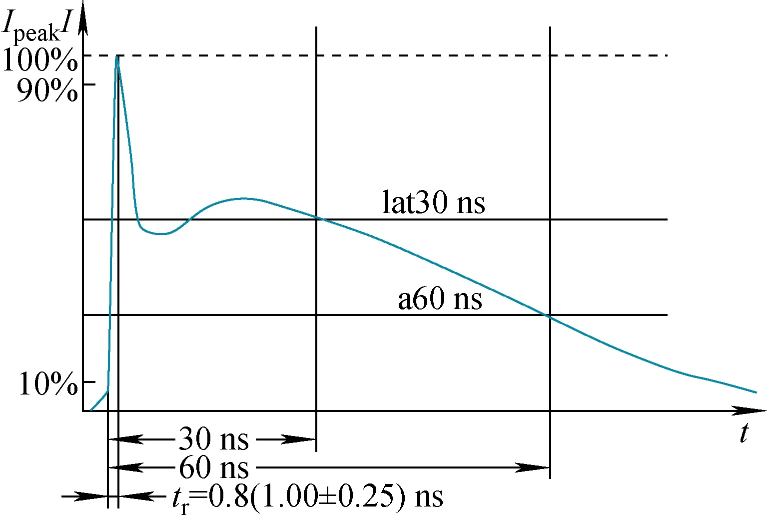
Fig.2 Current output waveform
The test setup is illustrated in Fig.3. The DUT was placed horizontally on an insulated tabletop, powered by a DC-regulated power supply (dual 1.2 V). Data were written and received through the serial port on the host computer software. During the test, the radiation field method recommended by NASA-HDBK-4002A was referred to reference [15]. A 10 cm×10 cm aluminum plate was discharged using an ESD generator, with one end of the plate grounded through a wire, and the ground wire was passed through a Rogowski coil connected to the oscilloscope[16].
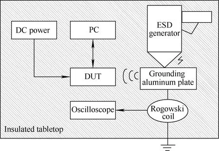
Fig.3 Schematic diagram of SESD test setup
The SEE simulation test equipment[17](as shown in Fig.4) in the National Space Science Center of the Chinese Academy of Sciences was utilized for the SEE test. The main technical parameters are listed in Table 2. To validate the laser test results, a heavy ion test was also conducted on a heavy ion accelerator of the Institute of Modern Physics of the Chinese Academy of Sciences.
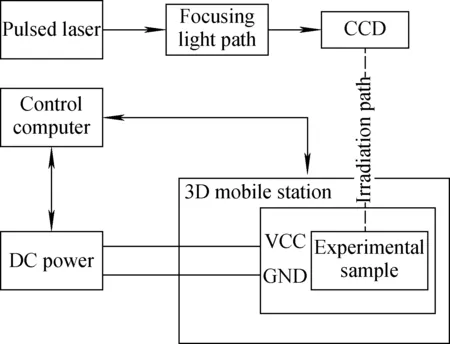
Fig.4 Schematic diagram of pulsed laser irradiation test equipment
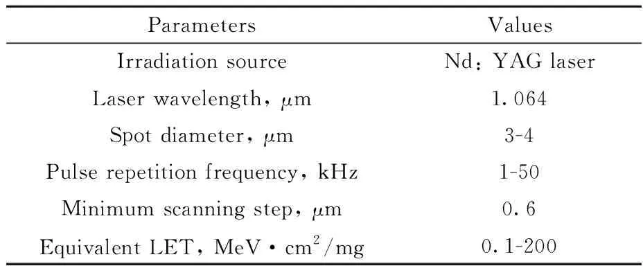
Table 2 Main technical parameters of pulsed laser SEE test equipment
3 Experimental results and discussion
In the present study, experiments were conducted in three aspects, namely, the characteristics of error numbers, the influences of different test modes (dynamic FF/static FF), and the influences of device structures, to investigate the similarities and differences in error numbers generated by flip-flop chains for SESD and SEE testing when the aforementioned test conditions were changed.
3.1 Characteristics of error numbers
A dynamic test mode was adopted, and FF data were written to study the differences and similarities of the overall characteristics of SESD and SESD with the change of discharge voltage and pulsed laser energy (heavy ion linear energy transfer (LET) value).Fig.5 illustrates the relationship between the number of soft errors on four trigger chains (Q3/Q5/Q6/Q8) and the discharge voltage of SESD. As shown in Fig.5, when the discharge voltage increased from 500 V to 14 kV, a test point was set every 1 kV. The soft errors were observed in the trigger chain at 6 kV, and the number of errors exhibited a trend of first increasing and then decreasing, and almost dropped to 0 at 14 kV. The maximum number of errors could reach 2000, and the number of errors would remain saturated within a discharge voltage range from 7 kV to 9 kV.
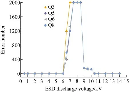
Fig.5 Relationship between number of soft errors and discharge voltage
Fig.6 illustrates the relationship between the number of soft errors of the four flip-flop chains and the pulsed laser energy/LET value of heavy ions. As the laser energy gradually increased from 704 pJ to 2960 pJ, the number of errors exhibited a gradual increase and no saturation state. The results of the heavy ion test under the same test conditions are shown in Fig.6, wherein when the LET value of heavy ion increased from 4.4 MeV·cm2/mg to 37.54 MeV·cm2/mg, the number of soft errors also exhibited a gradual increase and an unsaturated trend.
Based on the above analysis, under the same test conditions, the flip-flop chains exhibited different features of error numbers under the effects of SESD and SEE. As the ESD voltage increased, there was a saturation state, while during pulsed laser and heavy ion irradiation, the number of errors continuously increased with the increase of energy, but without a saturation state.
The main reason for these two different phenomena was the different ways in which the two effects produced errors. The SESD effect was mainly coupling on the power pin of the device, forming a transient voltage pulse between the power supply and the ground. And then the transient voltage pulse propagated to the power input end of the internal storage circuit. When the core power supply voltage dropped from the normal operating voltage to the negative minimum value, it was easy to cause the device power rail collapse effect, leading to soft errors of the memory cell.

Fig.6 Relationship between error number and pulsed laser energy/LET value of heavy ions
Because the two thousand-level flip-flops of this device shared the same power supply circuit, once the discharge pulse exceeded the threshold (6 kV for this device), it would cause multiple-bit upset (MBU) in the storage cell, and quickly propagated to the entire chain. By contrast, when pulsed lasers and heavy ions acted on the device, many electron-hole pairs were generated on the ion incident track and quickly collected by the transistor. These transient pulses generally produced single event upset (SEU) and would not propagate in the circuit. As the energy of incident particles increased, the probability of inducing errors rose. The experimental results of the present study were consistent with those of previous research[18]. In the pulsed laser experiment, the maximum pulsed laser energy reached 2960 pJ and the equivalent LET value was about 113 MeV·cm2/mg, which was far beyond the radiation resistance requirements of normal satellite devices. This indicated that devices fabricated with SOI process had better performance in radiation hardening of satellite to SEE, and it was according with previous simulation study[19-20]. An assumption was made that increasing the laser energy further would eventually lead to a saturation state or burning out, which would have been of no research significance and practical value.
3.2 Influences of different test modes
The similarities and differences of the effects of SESD and SEE on the trigger chain under the two modes of dynamic test and static test were investigated. The main difference between the two test modes was whether the data read-write clock signal continues working. Test conditions were set to dynamic FF and static FF, respectively. As shown in Fig.7, in the electrostatic discharge experiment, with the increase of discharge voltage, the number of soft errors of different trigger chains in the dynamic FF mode initially increased and then decreased. Meanwhile in the static FF mode, the number of errors would remain saturated after reaching 2000.
The reason for the different changes in the number of errors with the discharge voltage of the two test modes is that, in the static test mode, once data was written into the daughter board under test, the clock signal stopped, and the mother board and daughter board suspended data exchange and information transmission. Thus, the discharge pulse would not affect the reading and writing functions of the mother board in the SESD test. At the same time, in the dynamic test mode, the carrying capacity of the data serial port of the test circuit was limited. When the discharge voltage exceeded a certain value, the amount of error data induced on the daughter board by the discharge pulse was too large, which caused the reading and writing function of the serial port to be abnormal. In turn, a downward trend occurred in the number of errors after the saturation state. If Fig.7 is analyzed solely from the perspective of discharge voltage threshold, the threshold value of dynamic test was higher than that of the static test, which is related to the running state of the circuit and the refresh of the clock. In the dynamic test, the device was always in the charged state, which is not conducive to the injection of external signals. However, in the static test, the clock did not refresh and the ESD pulse had enough time to propagate in the trigger chain, thereby causing the threshold of the static test to be lower than that of the dynamic test.
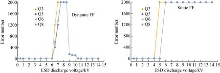
Fig.7 Relationship between number of errors of dynamic FF and static FF with discharge voltage
As shown in Fig.8, the number of soft errors of different trigger chains increased with the increase of laser energy in the laser simulated single event experiment. The growth trend of the number of errors in the two test modes was roughly the same, and there was no obvious difference in the order of magnitude. The essential difference between dynamic testing and static testing was whether the clock worked. The operating frequency of the read-write circuit of the flip-flop chain was 25 MHz, that is, in the dynamic test, the data was refreshed every 40 ns. But the transient pulse generated by the single event effect was only hundreds of picoseconds. As a result, the voltage drop rate was faster than the recovery rate, leading to the upset of stored information. This indicated that the test mode had little effect on SEE.
From the aforementioned analysis, the dynamic and static test modes affected the performance of the number of errors in the oversaturation state in the SESD test. However, in the SEE test, the different test modes had little effect on the overall trend of error number.
3.3 Influence of device structures
1) Topological structure
In consideration of the influence of different topologies in device design, an experiment was conducted according to the design information of the trigger chain in Table 1. When other conditions were consistent, Q2 was placed in a single row, while Q7 was placed in a double row.
Fig.9 shows that, in the SESD test, the topological structure of the flip-flop chain had basically no effect on the number of errors. However, in the SEE test, the number of errors generated by the double-row trigger chain Q7 was significantly higher than that in the single-row trigger chain Q2. To be specific, the topological structure of the flip-flop chain only affected the number of errors in SEE but had no significant effect in SESD. The reason for the above phenomenon is that the space ESD pulse passed through the power supply terminal-VCC and GND[21], and Q2 shared the same VCC with Q7. Thus, the change of placement mode would not affect the propagation of the discharge pulse on the power line. The principle of laser-induced SEE is that through the ionization of the laser and the device, additional electron hole pairs are generated to form the current pulse, resulting in soft errors of the device. It could be seen from the layout that the double-row structure (Q2) was arranged more compactly. Owing to the charge-sharing effect in scaled-down device[22], the double-row structure increased the probability of MBU and led to more errors.
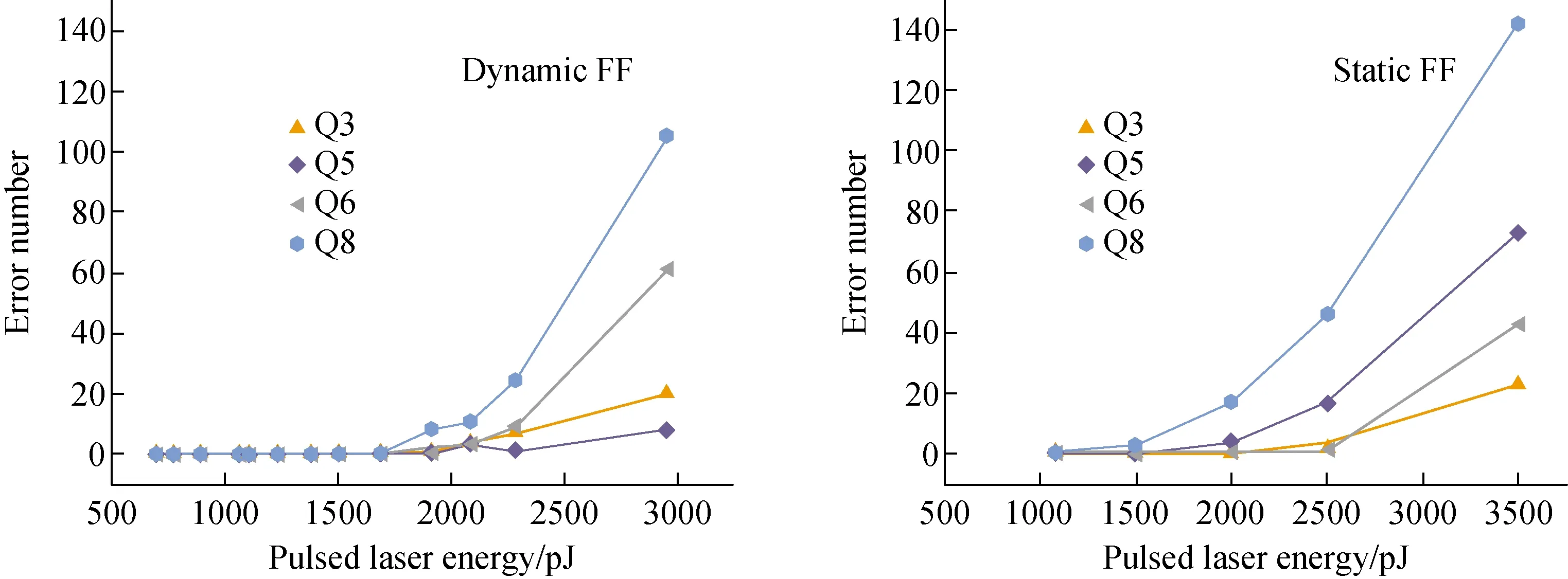
Fig.8 Number of errors of dynamic FF and static FF versus pulsed laser energy

Fig.9 Relationship between number of errors of Q2 double row/Q7 single row and SESD discharge voltage/pulsed laser energy
2) Radiation-hardened structure
According to part of the experimental data, the feature of the number of soft errors in different trigger chains was different under the same experimental conditions. Based on the design information of the trigger chain in Table 1, an experiment was designed to reveal the influence of a kind of radiation-hardened structure, DICE. Q4 was fabricated in DICE structure.
Fig.10 illustrates that in the SESD test, the threshold voltage and trend line of the flip-flop chain in the DICE structure had no difference with that in the structure of the ordinary two rows. Meanwhile, in the SEE test, the flip-flop chain in the DICE structure produced less errors. The experimental results demonstrate that the DICE structure exhibited a good radiation reinforcement effect against SEE, which is consistent with the simulation results in previous research[23-24]. The DICE structure adopted a novel four-node redundant latching structure. Its basic design idea was to use the redundant structure to back up the stored data. When a single node in the storage unit was flipped due to single particle bom-bardment, the backup data could recover the flipped data in a timely manner through feedback. However, since the internal power supply circuit of the DICE structure supplied power to each adjacent node, if the discharge pulse reached the threshold voltage, it was apt to cause errors in multiple storage bits at the same time. Thereby, the logically isolated dual interlocked storage structure became inoperative, and the redundancy measures failed in radiation-hardening for SESD.
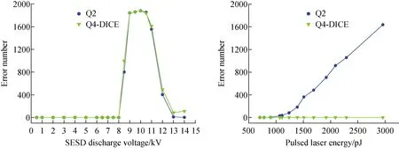
Fig.10 Relationship between number of errors of Q2/Q4-DICE and SESD discharge voltage/pulsed laser energy
4 Conclusion
In the present study, the space electrostatic discharge effect and single event effect of D flip-flop chains fabricated with 130 nm SOI process technology were studied using an ESD generator and a pulsed laser experimental facility. The results of the study reveal that: 1) The number of errors of the trigger chain was saturated in the SESD test, but increased constantly in the SEE test; 2) Different test modes would affect the oversaturation state and discharge voltage threshold of the number of errors in the SESD test, but would not affect the number of errors in the SEE test; 3) Different trigger chain arrangements would only affect SEE; 4) In the same process, the DICE structure would reduce the number of soft errors induced by SEE, but had no effect on SESD.
- 原子能科學(xué)技術(shù)的其它文章
- H-1NF仿星器標(biāo)準(zhǔn)磁場(chǎng)位形分析與高能量離子運(yùn)動(dòng)軌道模擬
- 鈾轉(zhuǎn)化生產(chǎn)線含氟廢水處理工藝設(shè)計(jì)
- 在線進(jìn)樣ICP-MS用于239Pu氣溶膠活度濃度連續(xù)監(jiān)測(cè)技術(shù)研究
- Degradation Characteristic of Proton Irradiated 8T CMOS Image Sensor
- Effects of Electron Irradiation at Different Energy and Fluences on Electrical Properties of InP HEMT Structure
- 模擬二回路環(huán)境下乙醇胺與3-甲氧基丙胺復(fù)合水工況對(duì)304L不銹鋼的緩蝕特性

