Effects of the critical breakdown path on the ignition performance in heaterless hollow cathodes
Bo YU (于博), Yanda LEE (李彥達), Xiaolu KANG (康小錄) and Qing ZHAO (趙青)
1 Center for Information Geoscience, School of Resources and Environment, University of Electronic Science and Technology of China, Chengdu 611731, People’s Republic of China
2 Shanghai Institute of Space Propulsion, Shanghai 201112, People’s Republic of China
Abstract The critical breakdown path(CBP)has a significant impact on the breakdown voltage curve and the ignition time of heaterless hollow cathodes(HHCs).To determine the pattern of the variation in the CBP position and its impact on ignition performance,a numerical model named the CBP evaluation (CBPE) was established in this paper to calculate the CBP of a HHC. The CBPE model can be used to screen various potential breakdown paths to identify those that are most likely to satisfy the Townsend breakdown conditions,which are denoted as CBPs.To verify the calculation accuracy of the CBPE model, 4.5 A-level HHC ignition tests were conducted on HHCs with three different structures.By comparing the test results and the calculated results of the breakdown voltage, the calculation errors of the CBPE under three HHC conditions ranged from 1.6%to 5.8%,and the trends of the calculated results were consistent with those of the test results.The ignition test also showed the characteristics of the breakdown voltage curve and the ignition time for the three HHCs.Based on the CBPE model,an in-depth analysis was conducted on the mechanism of the patterns revealed by the tests. The main conclusions are presented as follows: (1) the CBP always shifts from the long path to the short path in the HHCs with an increasing gas flow rate; and (2) the ignition time of the HHCs depends on the position of the CBP because different CBP positions can cause different mechanisms of heat transfer from the plasma to the emitter. This study can guide the optimization of the CBP position and the corresponding ignition times of HHCs.
Keywords: breakdown path, heaterless hollow cathode, breakdown voltage, ignition time,numerical calculation(Some figures may appear in colour only in the online journal)
1. Introduction
The heaterless hollow cathode (HHC) is an electron source device that is employed in electric propulsion systems. The HHC is often used as an ignition or neutralizer and is known for its fast-start characteristics [1–3]. Compared with conventional hollow cathodes, the HHC has the following advantages. First, HHCs use gas breakdown to heat the emitters,which makes the typical ignition time(defined as the time interval from breakdown voltage start to stable discharge) of HHCs less than 10 s, whereas the ignition of conventional hollow cathodes requires several minutes. Second, HHCs can avoid the risks caused by heater failure [4].Third, the HHC’s overall mass can decrease. Fourth, the circuit system of the heater can be removed.However,due to the lack of extensive HHC ignition tests,the cause of ignition failure,which is an important factor that affects the reliability of HHCs [5], remains unclear. Therefore, how to guarantee HHC ignition with a high success rate, low power and minimum damage in the desired location is currently the key problem in HHC performance research.
The HHC ignition process includes breakdown, heating,and keeping phases [6–8]. During the breakdown phase, the initial electrons accelerated by the high-intensity electric field between the cathode (specifically referred to as the cathode tube and the emitter)and the keeper could induce an electron avalanche, and the generated ions could produce a large number of secondary electrons after striking the cathode surfaces (defined in this paper as the surfaces of the cathode tube and the emitter exposed to the gap plasma). These secondary electrons can compensate for the electrons that enter the anode, which triggers a new electron avalanche. When a balance exists between the number of initial electrons and the number of the secondary emission electrons, the critical breakdown process is completed. After the completion of the breakdown process, the discharge between the cathode tube and the keeper can be converted to a glow discharge as a transition stage, which could then continue to increase the temperature of the cathode tube and emitter under the impact of ion bombardment until the emitter reaches the normal operating temperature. The heating process of the emitter is then completed.
In the HHC ignition process,under high voltage and high gap pressure, if the breakdown completes, the discharge will smoothly transition to the stable state. Hence, most research has focused on the breakdown phase. In a study by Michael
[9],the curve of the breakdown voltage of HHCs with the gas flow rate did not quantitatively agree with Paschen’s curve.However,Paschen’s law exhibits a high accuracy in predicting the(pd)minof HHCs.Second,Eichhorn[10]discovered that the breakdown voltage curves of HHCs on xenon (Xe) were always lower than the theoretically estimated curves and proposed the breakdown pendulum effect to explain this phenomenon, that is, because an HHC presents rotational symmetry in the structure, the spatial averaging of the Townsend ionization coefficients and the assumption of a forward scattering phenomenon could occur. However, the pendulum effect gradually disappeared after the gap pressure was higher than 20 Torr with a gap length of 1 cm. Arkhipov [11] conducted tests on 6 HHCs with different structures to determine the optimization direction of the ignition performance, determined that HHCs with a structure of an‘open-end emitter’had the best ignition performance, and revealed that the ignition time of a typical HHC ranged from 3 to 20 s, and the breakdown voltage ranged from 340 to 500 V for Xe. When the emitter reaches the operating temperature(usually greater than 1200 K, depending on the emitter material), the cathodic discharge could enter a stable self-sustaining arc discharge between the cathode and the anode. At this point, the cathode ignition process is completed. Daykin-Iliopoulos [5, 12] conducted experimental studies on how to reduce the breakdown voltage and suggested that reducing the keeper orifice diameter or using the keeper orifice with a reverse chamfer can reduce the breakdown voltage. Lev [13–17] investigated the thermal characteristics and lifetime influencing factors of the ignition process of 0.1–1.5 A level HHCs. By studying the heat distribution during the heating process of the emitter, some optimization strategies for the performance of HHCs were identified,low thermal conductivity refractory metals and high aspect ratio geometries were applied to maintain the required temperature for the heating phase.
In summary, in the research on the ignition performance of HHCs, researchers have elevated the ignition performance of HHCs to a level that satisfies preliminary engineering applications. However, some ignition problems remain:(1) methods are required to control the ignition time; and(2) HHCs with certain structures and in certain working conditions have the problem of a successful breakdown but do not maintain the generated plasma. These problems are related to the fast-start of HHCs and the reliability of HHC ignition, which restricts further engineering applications of HHCs. Moreover, few studies focus on these issues, and relevant theories to guide the optimization design are lacking.Therefore, this paper conducted an in-depth study of the previously mentioned issues.
The ignition time and failure to maintain ignition involve the related physical processes during the early stage of gas discharge. The HHC breakdown process is a discharge process between two nonparallel electrode plates. In existing theories, Paschen’s law cannot adequately describe the discharge process. Instead, the breakdown between the nonparallel electrodes begins from a critical region [18, 19], and this critical region position depends on the gap pressure and the gap structure. Once the critical region induces the breakdown, the breakdown process of the entire gap can be completed in an instant. Therefore, we believe that a critical region also exists in the HHC breakdown process and has a certain relationship with the HHC ignition performance.
Based on these statements, a breakdown determination model that is based on the Monte Carlo collision model(MCC model) is established in section 2. This model determines the critical breakdown path(CBP,defined as the initial breakdown path between two nonparallel electrodes) among the potential breakdown paths(PBPs,which are defined as the paths that can induce gap breakdown and can be considered candidates for CBPs). In section 3, ignition tests on three HHCs with different structures were used to verify the correctness of the model.Moreover,both the changes in the CBP and the correlation between the ignition time and the CBP position were obtained. Finally, in section 4, based on the underlying mechanisms revealed by the numerical model in section 3 (using the test results), a strategy for reducing the ignition time is proposed.
2. Simulation model
To observe the CBP in the HHC gap, a numerical model,namely, the CBP evaluation (CBPE), is presented in this section. The purpose of the model is to capture the path with the highest probability of achieving the Townsend breakdown in a large number of PBPs in the HHC gap. The CBPE employs a method of tracking particles along fixed paths to solve the problem of particle transportation and employs the Monte Carlo model to describe the collision process. Note that the CBPE tracks only the particles established in the computational process (including the initial electrons and the electrons and ions generated by the ionization events) and does not track all of the real particles.
In the breakdown process of a nonuniform electric field[18,19],a large number of positive ions can be generated due to the ionization collision triggered by some initial electrons.These positive ions move towards the cathode under the action of an electric potential difference and generate a substantial amount of secondary electrons on the cathode surface.If the secondary electrons compensate for the consumed initial electrons in one region, the region is considered as the critical region, and a critical breakdown could be induced locally. A local breakdown could spread to the entire gap in an instant.
Based on the physical basis, the main five steps of the CBPE model are listed as follows:
(1) To find the PBPs and generate the meshes in the HHC gap.
(2) To establish the initial electron number of each PBP in the cathode asne,initial.
(3) To set or update the voltage differenceU0between the cathode and the keeper. These initial electrons move along the PBP towards the keeper and trigger a large number of collisions among particles along the way.When all of the electrons move to the keeper, the number of all ionization collisions that are triggered along the path, and the number of generated ions are counted.
(4) Based on the number of ions in each PBP, the number of secondary electronsγncan be calculated, and the path with the most secondary electrons (γn,max) is selected as a temporary CBP.
(5) By comparingne,initialandγn,maxof the temporary CBP,whether the gap can achieve the critical breakdown of the current iteration cycle is determined. Ifγn,maxis considerably more or less thanne,initial,then adjustU0and return to step (3). Ifγn,maxandne,initialare close enough, it is believed that this temporary CBP can achieve the critical breakdown. The temporary CBP of the last iteration cycle is recorded as the final CBP,and the calculation converges.
The calculation details are described below.
2.1. PBP generation
The PBP is the path of electrons that move from the cathode surface to the keeper. Therefore, we need a method to determine the PBP. In published papers, Macheret [20]established a forward-back model for electron flow and believed that, in the low-pressure breakdown process, electrons are scattered under the binding force of an electric field.Therefore, this paper assumes that most of the electrons should move with the electric field,and the electric field lines are treated as PBPs.
The method for dividing the PBPs is shown in figure 1.First, at the cathode surface of the HHC (specifically, the surfaces of the cathode tube and emitter), several starting nodes of the electron motion are selected, and the local electric field lines are drawn from these nodes to the keeper.Note that excess starting nodes are not needed as long as the initial starting nodes can represent the critical breakdown positions. In the calculations and experiments in this paper,67?68 starting nodes of electron motion are established for the three HHCs that are used (LYJ-100 series). Second,because the pressure distribution in the HHC gap may not be uniform, the number of local background gas numbers needs to be re-acquired in every computation node. Here, we orthogonally divide the PBPs using several equipotential lines, where the potential difference between two adjacent equipotential lines isΔU. The intersection points are the computational nodes in the PBP, and the path between two adjacent computational nodes is the micropath of electron motion. For each node, the collision between the electrons and background gas is calculated.
The detailed configurations of the LYJ-100 series are presented in section 3.1. Note that the only difference between LYJ-100-B and LYJ-100-A is the keeper orifice diameter.Thus,the distribution of the PBPs for LYJ-100-B is also shown in figure 1(a),while the structural change in LYJ-100-C is relatively large, as shown in figure 1(b).
2.2. Collision probability
Assuming that some primary electrons will be presented inside the gas that is fed into the cathode, for each PBP, the initial electronsne,initialrepresent these primary electrons and depart from the cathode surface and move towards the anode.The voltage differenceU0between the cathode and the keeper drives the electrons towards the keeper and triggers a collision process with the background neutral gas (Xe) along the way.
According to section 2.1,when electrons move along any PBP, the electrons lose the same electric potential energy
(ΔU e,· e is the elementary charge of 1.6×10?19C) when they pass each micropath. The kinetic energy simultaneously increases by the sameΔU e.· An electron is able to collide with a neutral gas, and the collision type can be an elastic,excitation, or ionization event.
According to the MCC model [21], the collision probability of an electron in a neutral gas during an extremely short time (generally<10?8s)Δtis

wherefenis the collision frequency between electrons and atoms, andΔtis the time (s) required for an electron to pass through a micropath [21]. Thefencan be computed as

whereNnis the number density of neutral gases (m?3),venis the relative velocity between the electrons and atoms(m s?1),andσT(Ek,e) is the total collision2cross-section between the electrons and the neutral atom (m).
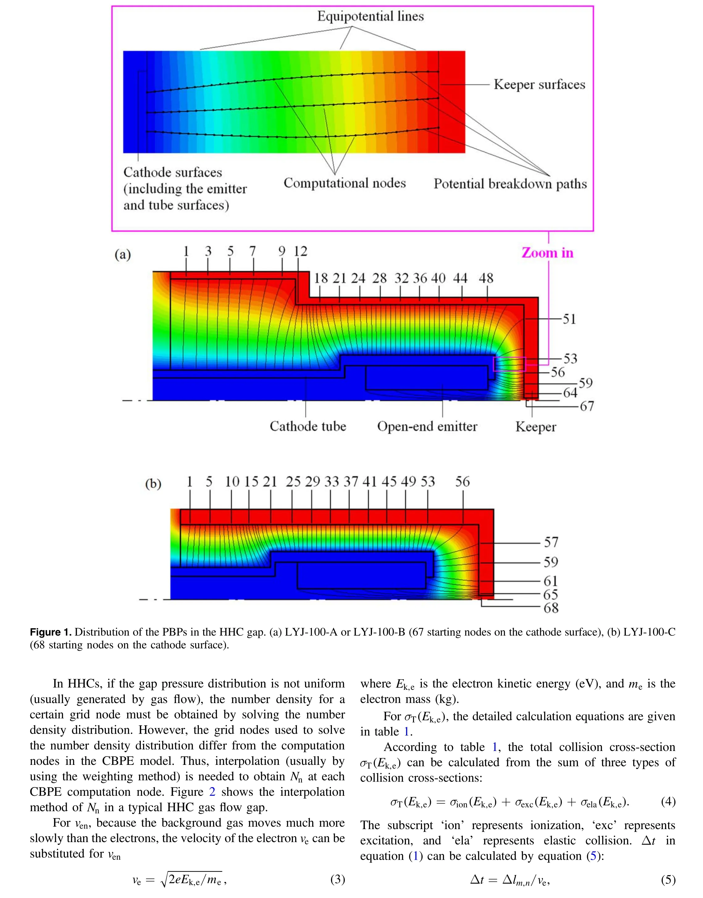
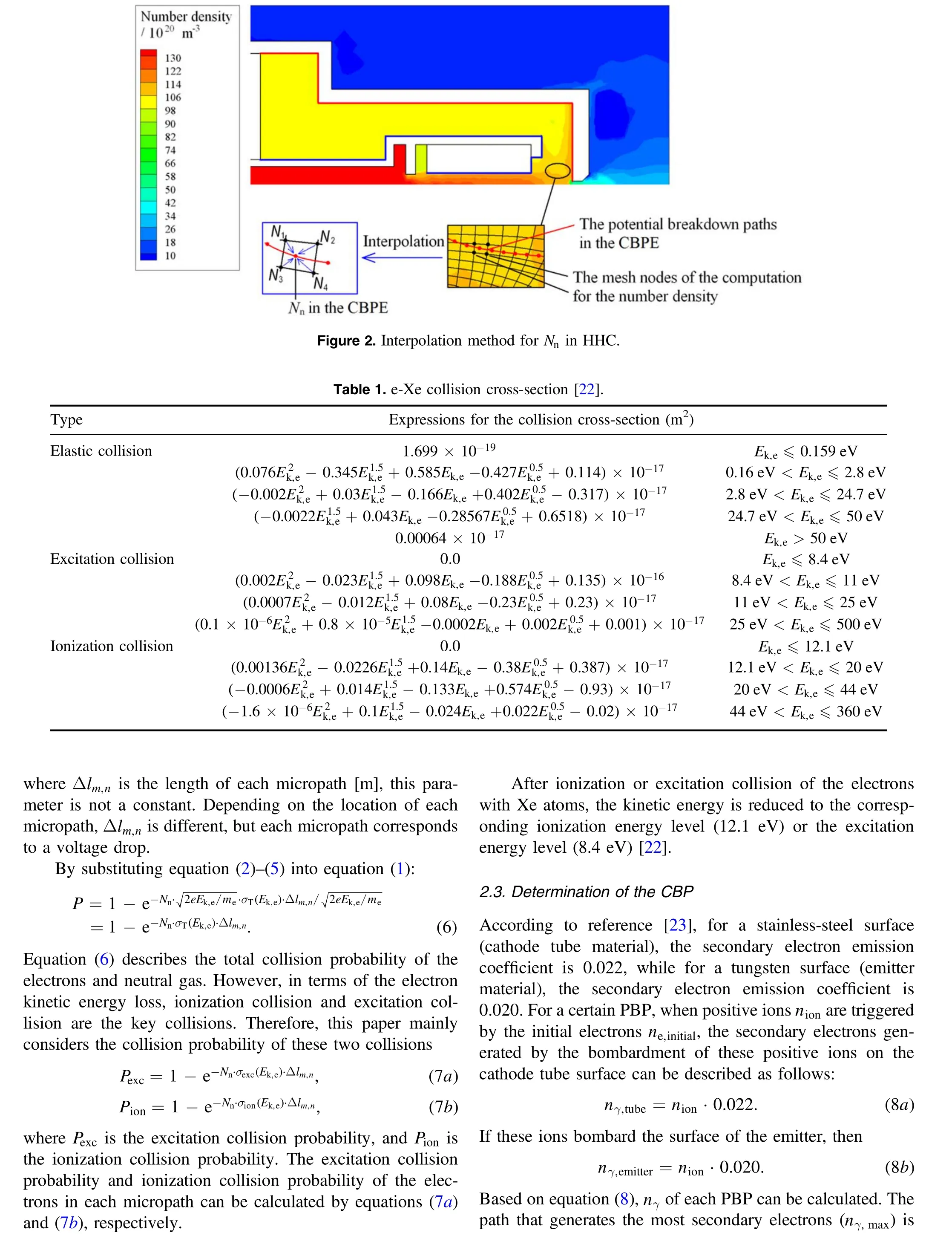
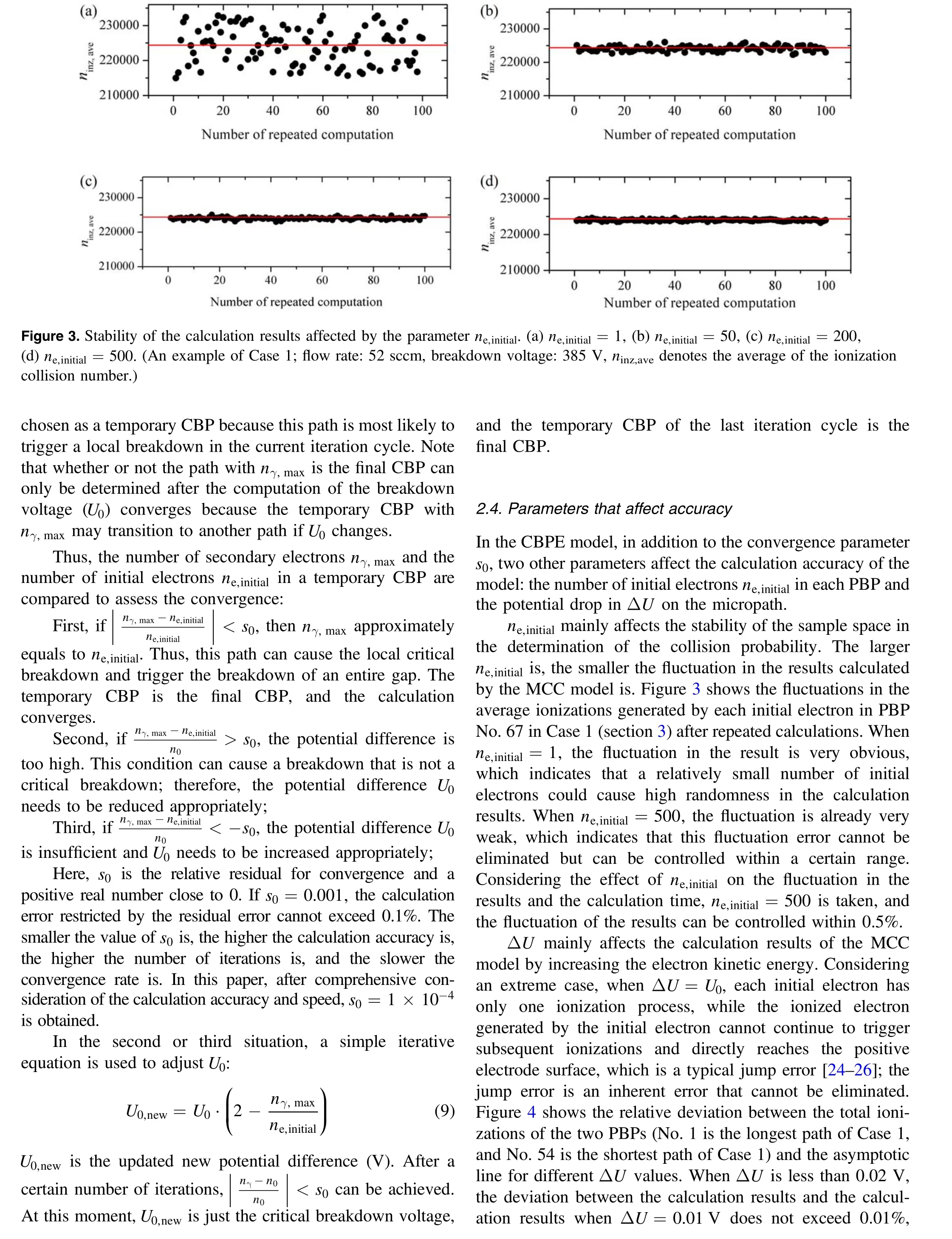


Figure 4.Total ionization number in two PBPs affected by the parameter ΔU.(a)Path No.1,(b)Path No.54.(An example of Case 1;flow rate: 52 sccm, breakdown voltage: 385 V, ninz,total denotes the total ionization collision number.)
3. Results
In this section, ignition tests for three HHCs with different structures were conducted to measure the breakdown voltages and ignition time. Due to the constraints of the experimental conditions, we cannot verify the calculation accuracy of the CBP in the most direct way. Therefore, the test value of the breakdown voltage was compared with the calculated value to verify the calculation accuracy of the CBP using the CBPE model. Subsequently, the tests also showed the regularity of the change in the breakdown paths of HHCs with different structures and the law of ignition time to introduce the discussion of the physical mechanism by which the CBP affects the ignition performance (section 4).
3.1. Experimental setup
A cathodic ignition test was carried out in a vacuum tank
(1 m×Φ0.6 m), as shown in figure 5. The pumping system mainly consists of a mechanical pump, a molecular pump,and a cryopump. During the normal operation of the hollow cathode, the pressure inside the tank can be kept below 8.0×10?4Pa (6.0×10?6Torr). The HHC has two power supply systems: one ignition source (3000 V, 10 A) that is located between the cathode (‘ignition ?’and‘discharge ?’)and the keeper (‘ignition +’) and one steady-state discharge power source (150 V, 30 A) that is located between the cathode and the anode (‘discharge +’).
In the ignition test, three HHCs with different structures were employed(LYJ-100-A,LYJ-100-B,and LYJ-100-C;the configurations are presented in figure 6). The only difference between LYJ-100-A and LYJ-100-B is the keeper orifice radius (dimension a), while LYJ-100-C has a very different structure compared with the other two cathodes.Note that the right side insulator has a sealing effect to block the gas flow,and a ladder structure of the keeper is lacking between the right side insulator and the keeper top in LYJ-100-C. Thus,the dimensions g and h do not have to be displayed for LYJ-100-C.
The HHCs of the LYJ-100 series(working fluid:Xe)are mainly used as the neutralizer cathode of 1.35 kW class Hall thrusters, whose rated discharge current is 4.5 A. Under normal working conditions, the gas flow rate is between 3.1 and 3.6 sccm.The working fluid of the LYJ-100 series HHCs is Xe. In the discharge process with the anode plate, the plume is blue-green.
As shown in figure 7,the breakdown voltage and ignition time (quantitatively defined as the time interval between the moment of starting the potential of the keeper and the moment of|Ia?4.5 A|/4.5 A<0.05 A and Ip–p=0.2 A,where Iais the discharge current measured by the electrical power system, 4.5 A is the rated current, and Ip–pis the peak-to-peak value of the discharge current) could be measured by the volt–ampere characteristic curve of the HHC ignition process.First, the potential of the cathode was set to 0 (ground potential),the potential of the anode was set to 100 V,and the potential of the keeper was set to 300 V.Second,the potential of the keeper was increased by 1 V every 10 s until the breakdown discharge between the cathode and the keeper was triggered. With an increasing keeper potential, the data acquisition system of the power source recorded the volt–ampere curve over time. The highest point in the ignition voltage curve (black solid line) is denoted as the breakdown voltage. Third, after discharge occurred between the cathode and the keeper, the discharge was simultaneously triggered between the cathode and the anode.Fourth,the anode current was gradually increased over time until it reached 2.7 A(60%of the rated discharge current), and the ignition power was turned off. Last, the cathode gradually transitioned to the stable working state until the steady-state operating point was reached.
Note that factors, such as the unstable gas flow rate and the vacuum pump vibration, may produce different breakdown voltages and ignition time in multiple ignition tests.Therefore, when measuring the breakdown voltage and the ignition time, we take the average of five measurements to determine the final result of these two physical parameters.
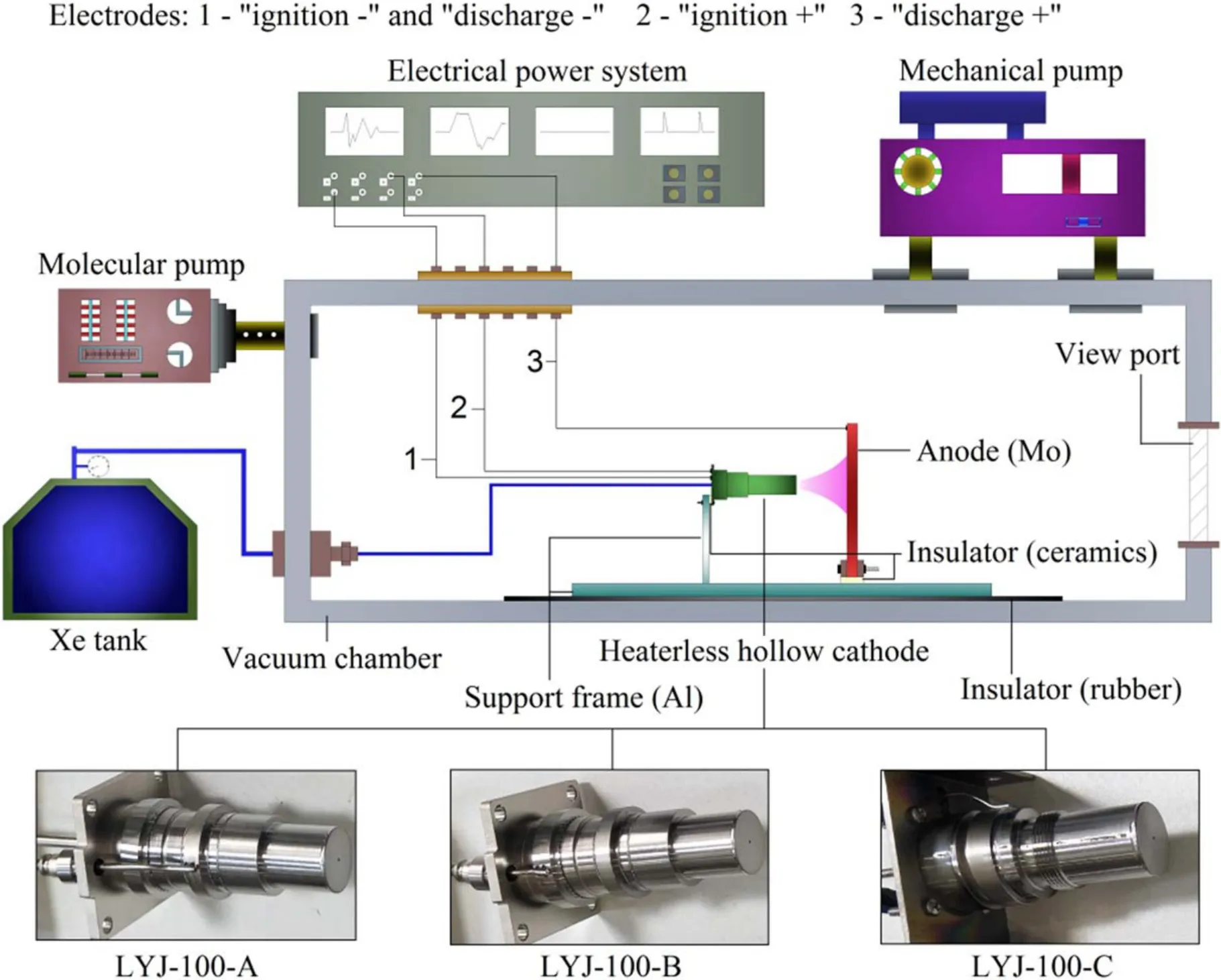
Figure 5.Schematic of the HHC ignition test.
3.2. Breakdown voltage curve
We have made some attempts to determine the experimental methods of the CBP. After the ignition test, the HHC was dissected to observe the traces on the surface of the cathode tube and the emitter.We hoped to use these traces to identify the CBP. However, the traces produced by one HHC breakdown were not obvious; therefore, multiple ignitions were utilized. However, after a large number of ignition tests, the HHC produced black sediments that cover every surface(composition analysis showed that the sediments are W and Mo), which means that this method completely failed.Therefore, we can only indirectly verify the calculation accuracy of the CBP based on the comparison of the breakdown voltage.
Figure 8 shows the comparison between the experimental breakdown voltage curves and the calculated breakdown voltage curves of three HHCs with different structures. Furthermore, the CBP variations (the CBP numbers in figure 8 are consistent with those of figure 1) predicted by the CBPE model are also indicated at the corresponding operating points. According to the comparison between the experimental results and the calculated results of the HHCs with three structures, the CBPE model had a calculation accuracy of 1.4%–5.8%in the breakdown voltage,and the trend of the calculated results was in good agreement with that of the experimental results.According to the experimental results of the breakdown voltage curve, the transition region is a straight line. The existence of the straight-line region makes the breakdown voltage curve quite different from the classic Paschen curve. We believe that the CBPE model is able to accurately capture the trend of the breakdown voltage curve because the CBPE model can accurately capture the CBPs.Note that the existence of the transition region has already been reported [5, 9]. In [5, 9], the breakdown voltage curve has a region that is close to a straight line, but the relevant mechanism has not been reported.
In addition, the characteristics of the breakdown voltage were closely related to the structural characteristics of the three HHCs. The orifice diameter in Case 2 was smaller than that in Case 1,which caused an increase in the gap pressure of Case 2. Thus, the breakdown in Case 2 was achieved at the minimum voltage with a smaller gas flow rate than that in Case 1, but the breakdown voltages in the rising region of Case 2 were higher than those of Case 1.The orifice diameter in Case 3 was equal to that in Case 2, but both cases had different d, e, f, and i values (the dimension description is presented in figure 6).In particular,the f value of Case 3 was shorter than the g value of Case 2, which caused a higher breakdown voltage for Case 3 at a gas flow rate of less than 10 sccm, while the numerical values in the transition and rising regions of Case 3 were similar to those of Case 2.
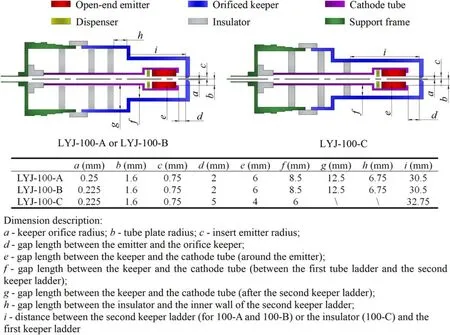
Figure 6.Configuration of HHCs employed by the ignition test.
The CBP transition order with respect to the gas flow rate in Case 1 is almost equivalent to that in Case 2,which can be expressed as Region 1–Region 2–Region 3–Region 4 (definition of‘Region’is presented in figure 9)with an increasing gas flow rate, while the transition order of Case 3 is Region 1–Region 3–Region 4–Region 2. From the overall trend, the CBP transitioned from the region with a longer path to the region with a shorter path,but the order of the CBP transition depended on the HHC configuration. With an increase in the gas flow rate, the CBP transition always started from the region of the longest path and ended in the region of the shortest path. The CBP transition mechanism will be further discussed in section 4.1.
3.3. Ignition time
Figure 10 shows the ignition time results of the LYJ-100 series HHCs. In some ignitions with low gas flow rates, a breakdown can occur,but the ignition cannot persist until the stable discharge stage. For this reason, these working conditions are indicated with fractions in the figure to show the ratio of successful ignitions to successful breakdowns.For the working conditions that are not marked, the default value is‘5/5’. Figure 10 also indicates the critical breakdown region that corresponds to each operating point, which reveals a certain regularity in the ignition time (originally, the ignition time had no obvious regularity). When the CBP was located in Region 1,the difficulty of ignition was the highest,and the ignition time for all three working conditions ranged from 15 to 40 s. Region 2 ranked second, and the ignition time ranged from 10 to 20 s. Region 3 and Region 4 had short ignition times, which ranged from 4 to 12 s. Note that the lowest ignition time was obtained from the operating conditions in Region 3.Because all 3 HHCs exhibited this pattern,we infer that the ignition time is related to the position of the CBP. The correlation between the ignition time and the CBP position will be further discussed in section 4.2
4. Discussion
The experimental results in section 3 show that:(1)the law of the CBP shifts at different gas flow rates, and (2) the law of the ignition time changes with different CBP regions. In this section, the CBPE model is employed to further discuss the two laws to prove the correctness of the laws and reveal the relevant underlying mechanism.
4.1. CBP transition

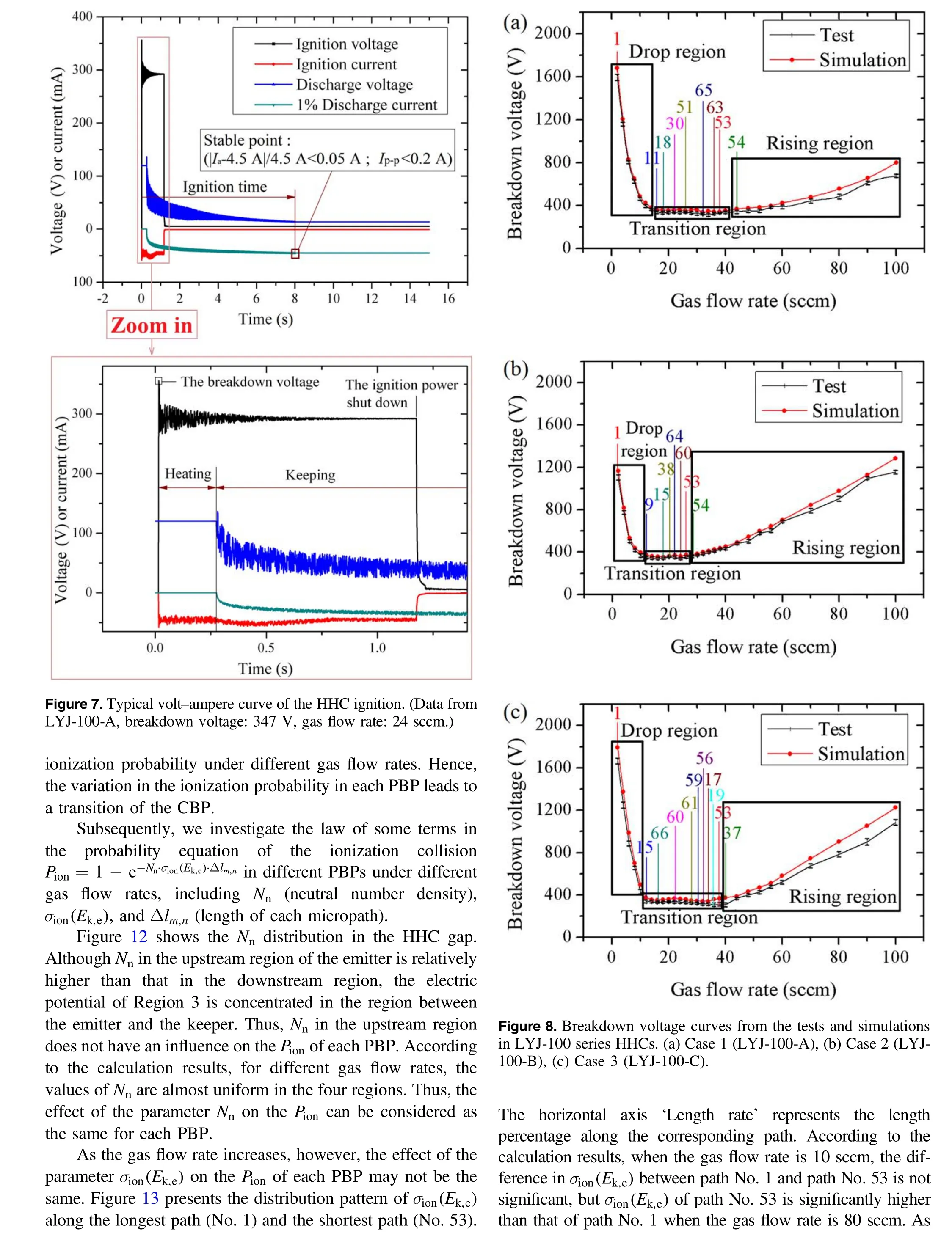

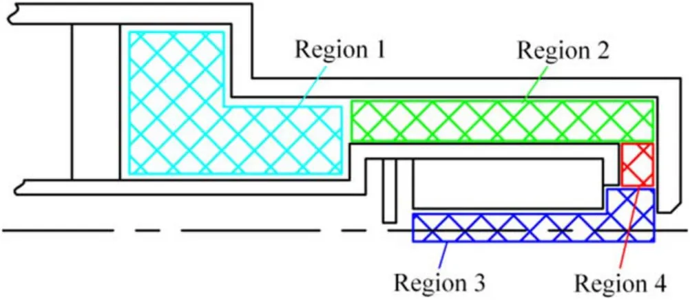
Figure 9. Region division for the CBPs.
A mechanistic analysis about the targetσion(Ek,e) was performed to investigate the patterns in variation. Sinceσion(Ek,e)is a function ofEk,e,figure 14 shows the distribution ofEk,ealong paths No. 1 and No. 53. According to the calculation results, the difference in the kinetic energy of electrons at a low flow rate(10 sccm)between path No.1 and path No. 53 is not significant; however, at a high flow rate(80 sccm), the electron kinetic energy of path No. 53 is significantly higher than that of path No.1,which directly causes changes inσion(Ek,e).
To reveal the underlying mechanism ofEk,e, figure 15 shows the contours of the number of electron-atom excitation events (defined as the ‘EXC number’) for all the computational nodes in the HHC gap (LYJ-100-A) under 10 sccm,30 sccm, 60 sccm, and 80 sccm. (In addition to ionization collision, excitation collision is also a main physical process that affects the kinetic energy of the electrons.) Because the computational mesh is only composed of electric field lines and equipotential lines, the shape of the computation domain differs from the regular HHC gap configuration. This calculation result reveals that there is no significant difference in the number of induced collisions for all the paths in the gap when the flow rate is 10 sccm.As the gas flow rate increases,the longer the path is, the higher the number of induced collisions is, which causes a decrease in the electron kinetic energy of the long path at the flow rate.
In summary,the CBP of HHCs varies with changes in the gas flow rate. These changes in the path are mainly affected by the path length and electron kinetic energy.In the case of a low flow rate, the difference in the electron kinetic energy in different paths is not significant; therefore, regions with long paths are more prone to breakdown.However,when the flow rate increases, the long-path excitation collision effect is significantly enhanced, so the loss of electron kinetic energy in the long path could be more serious than that in the short path, and the CBP could gradually transition to a short path.
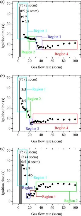
Figure 10.Test results of the ignition time in LYJ-100 HHCs.(a)Case 1(LYJ-100-A),(b)Case 2(LYJ-100-B),(c)Case 3(LYJ-100-C).(The numerator of the fraction denotes the number of successful ignitions,and the denominator of the fraction denotes the number of successful breakdowns.)
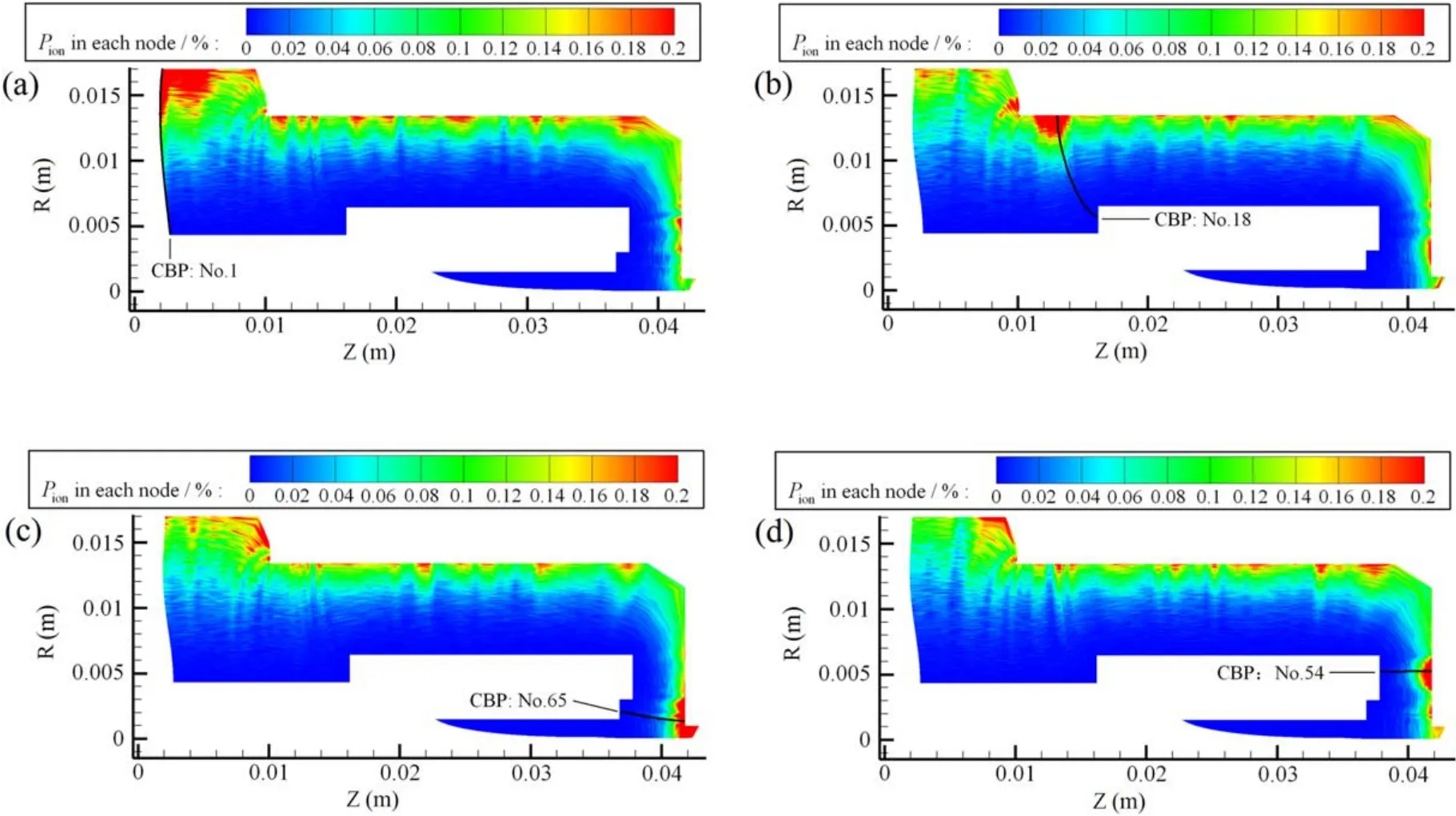
Figure 11.Distribution of the ionization probability in each node in the LYJ-100-A. (a) 10 sccm, (b) 20 sccm, (c) 32 sccm, (d) 50 sccm.
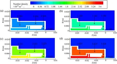
Figure 12.Number density distributions at different flow rates in the LYJ-100-A case. (a) 20 sccm, (b) 40 sccm, (c) 60 sccm, (d) 80 sccm.

Figure 13.Distribution ofσi on (E k,e) along the two PBPs. (a) 10 sccm, (b) 80 sccm.

Figure 14.Distribution of Ek,e along the two PBPs. (a) 10 sccm, (b) 80 sccm.
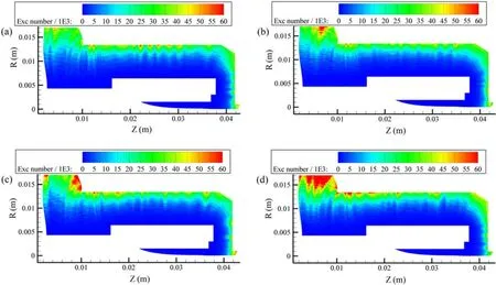
Figure 15.Contours of the excitation collision number in the HHC gap. (a) 10 sccm, (b) 30 sccm, (c) 60 sccm, (d) 80 sccm.
4.2. Ignition time
According to the ignition time results,for the three HHCs in this paper, when the CBP of the local breakdown is located in a specified region, the ignition time of the three HHCs is almost the same.We believe that this similarity is not a coincidence and that a certain intrinsic pattern exists.The discharge phase that is directly associated with the ignition time is the emitter heating,that is, the bombardment effect of the ions in the HHC gap discharge on the cathode surfaces.Furthermore,the distribution of the total potential energyEtotalp,i‐of newborn ions in each node in the heating phase was examined (parameterEtotalp,i‐is described in equation(10),and the electric potential energy of a newborn ion can be completely converted to kinetic energy when the ion reaches the cathode surfaces with 0 potential).Ep,iis the potential energy(eV)of every newborn ion in each node,andncis the number of newborn ions of each node.

However, the HHC heating process is an unstable discharge process, and the motion of the plasma in the gap changes over time. Meanwhile, the process from the breakdown phase to the heating phase is continuous, and the path with the maximumEtotalp,i‐in the breakdown phase should maintain this dominant state for some time.Hence,the differences in theEtotalp,i‐values between the breakdown phase and the heating phase paths are assumed to be the same, this assumption is the ‘difference feature assumption’.This is an important assumption,but no theory can directly demonstrate its correctness. However, this assumption can better explain the pattern of ignition time (a detailed explanation is provided below). Therefore, we believe that the assumption is reasonable.
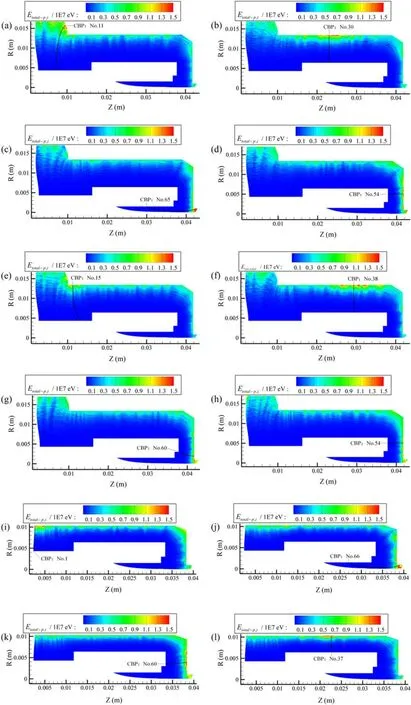
Figure 16.Distribution of theEion,total for different gas flow rates in three HHCs.(a)LYJ-100-A,16 sccm;(b)LYJ-100-A,22 sccm;(c)LYJ-100-A, 32 sccm; (d) LYJ-100-A, 44 sccm; (e) LYJ-100-B, 18 sccm, (f) LYJ-100-B, 20 sccm; (g) LYJ-100-B, 24 sccm;(h) LYJ-100-B, 28 sccm; (i) LYJ-100-C, 10 sccm; (j) LYJ-100-C, 16 sccm; (k) LYJ-100-C, 22 sccm; (l) LYJ-100-C, 40 sccm.
TheEtotalp,i‐distribution of the breakdown phase is presented in figure 16, which shows the heating phase based on the difference feature assumption. According to the calculation results shown in figure 16, the CBP is located in the region of the maximumEtotalp,i‐because the CBP must have the highestEtotalp,i‐among all the PBPs to induce the most secondary electrons in the breakdown phase. As a result, the CBP region can be considered the region with the largest heat flux from the ions to the cathode surfaces in the gap. Therefore, the CBP position has a significant effect on the mechanism of the heat transfer from the plasma ions to the cathode surfaces during the heating phase. (1) If the CBP region contains a cathode tube between the plasma and the emitter to block the heat transfer (for example, the CBP is in Region 1 or Region 2),then the heat transfer process from the plasma to the emitter in the CBP region could increase the thermal resistance of the cathode tube (this heat transfer process is defined as ‘a(chǎn)n indirect heat transfer to the emitter’), and therefore, heating the emitter is difficult, which could lower the ignition success rate or increase the ignition time. (2) If the CBP region does not contain a cathode tube between the plasma and the emitter(for example,the CBP is in Region 3),then the plasma in the CBP region could directly transfer heat to the emitter(this heat transfer process is defined as‘a(chǎn) direct heat transfer to the emitter’), and the emitter should have a relatively low resistance during heating (the heating process of the emitter is relatively easy), which could reduce the ignition time.
In summary, the mechanism based on the difference feature assumption can explain the change pattern of the ignition time well.Moreover,based on the change pattern,an optimization strategy for reducing the ignition time is proposed. By adjusting the gap structure, the shift in the CBP with an increase in the gas flow rate can be controlled to ensure that the CBP can be moved to Region 3 with a low gas flow rate to reduce the ignition time. This optimization strategy was applied to the design of the LYJ-100-C, and the ignition time at a low gas flow rate was reduced(flow rate:16 sccm, ignition time: 4.3 s).
5. Conclusion
In this paper, we established a numerical model named the CBPE to study the effect of the CBP on the ignition performance of the HHC. In addition, the calculation accuracy of the CBPE was verified with breakdown voltage data, and the calculation error ranged between 1.4% and 5.8%. Based on this finding,the impact of the CBP on the ignition process of HHCs and relevant mechanisms were investigated using test results and calculation results from the CBPE model:
(1) When the gas flow rate changes from low to high, the electron kinetic energy in the long path can continue to decrease due to the increasing excitation collision, and the ionization collision probability of the short path gradually increases. Thus, the CBP in the HHC always transitions from the long path to the short path.
(2) During the heating phase in the discharge, the CBP region can be approximated to the peak region of the heat flux to the cathode surfaces and has a significant effect on the physical mechanism of heat transfer in the heating phase, which yields a short ignition time with the direct heat transfer that occurs in the CBP region.The ignition time in the CBP region, where the heat is indirectly transferred to the emitter,is relatively long,or the maintaining ignition is not feasible.
Combining these two conclusions, the position of the CBP for different HHC structures and gas flow rates can be obtained, and thus, the ignition time and success rate of ignition can be controlled. Moreover, this study can help optimize the minimum ignition time of HHCs at low gas flow rates.
However,some of the conclusions of this paper are based on the theoretical inferences obtained by the simulation results, which are relatively similar to the experimental results. Therefore, in future studies, when the experimental conditions achieve a certain level, targeted verification tests should be carried out to more intuitively confirm the relevant laws and mechanisms of the CBP in HHCs.
 Plasma Science and Technology2020年6期
- Plasma Science and Technology的其它文章
- First-principles study on the mechanical properties and thermodynamic properties of Mo–Ta alloys
- Formation mechanism of Al2O3/MoS2 nanocomposite coating by plasma electrolytic oxidation (PEO)
- Estimation of the sheath power dissipation induced by ion cyclotron resonance heating
- Influence of toroidal rotation on the tearing mode in tokamak plasmas
- Conversion between Vickers hardness and nanohardness by correcting projected area with sink-in and pile-up effects
- In-port-plug transmission line design of the ITER plasma position reflectometer
