Properties of intermediate-frequency vacuum arc in sinusoidal curved contact and butt contact
Ziang TONG (佟子昂), Jianwen WU (武建文), Wei JIN (金巍) and Jun CHEN (陳均)
1 School of Automation Science and Electrical Engineering,Beihang University,Beijing 100191,People’s Republic of China
2 Guizhou Tianyi Electrical Co., Ltd., Zunyi 563002, People’s Republic of China
Abstract In this report, two new contact structures of a vacuum interrupter with a sinusoidal curved surface are proposed to improve the capability by increasing the surface area. The experimental investigation of vacuum arc at intermediate frequency (360-800 Hz) was conducted and the results were compared with a butt contact with the same contact diameter(41 mm)and the same material. By analyzing the arc behavior, arc voltage characteristics, arc energy, current interrupting capacity, ablation of the anode contact and condensation of the arc products at a 3 mm gap,the differences in their vacuum arc characteristics were determined. The correlations of their arc energy with the amplitude and the frequency of the current were also achieved.Analysis suggests that the ruled curved contact has strong application potentiality because of its low arc energy, low arc voltage noise and arc voltage peak, light ablation on the surface of the anode contact and high interrupting capacity.
Keywords:sinusoidal curved surface,intermediate frequency,voltage characteristics,arc energy,vacuum arc properties, arc behavior
1. Introduction
In an intermediate-frequency power supply system of 360-800 Hz, although the shortening of the current arc ignition cycle reduces the energy injected into the arc gap, the increase of the frequency leads to a significant increase of di/dt when the current crosses zero [1]. It is difficult for a traditional air switch to meet the demand in an aircraft intermediate-frequency power supply system with increasing capacity. A vacuum switch uses vacuum as the arc extinguishing intermediate with strong interrupting capacity,small size, light-weight, extremely high service life, reliability and safety. Given its excellent performance, it is highly suitable for application in an aviation power supply environment,which is extremely sensitive to air pressure and temperature.
One of the main objectives in the field of vacuum switches in recent years has been the improvement of the interrupting capacity of vacuum switches using artificially designed magnetic fields [2-5].Axial magnetic field contacts weak the magnetic constriction of vacuum arc by an axial magnetic field. The vacuum arc is evenly distributed on the surface of the contact so that the arc voltage and the ablation of the contact can be reduced[6-9].Transverse magnetic field contacts drive the vacuum arc to move rapidly on the surface of the contact by a transverse magnetic field,thereby avoiding the erosion of the arc on the contact surface for a long time[10-13].
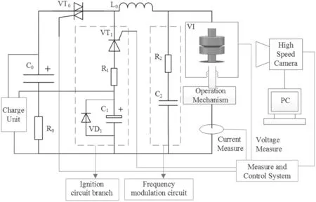
Figure 1.Schematic diagram of the intermediate-frequency experimental system.
In addition to magnetic field, the contact surface area is also an important factor that affects the performance of the vacuum switch [14]. It is believed that the increase of the effective contact area can improve the interrupting capacity of the vacuum switch [15]. It has been pointed out that the interrupting performance of the vacuum circuit breakers is proportional to the effective area and the diameter of the contact [16], and the effective area has a direct effect on the diffusion and absorption of plasma and the metal vapor in the arc-gap when the current crossed zero [17, 18]. Furthermore,the effects of contact diameter on the anode activities and interrupting capacity were researched for AMF vacuum interrupters with a cup type contact[19,20].In this work,two new types of contact with a sinusoidal curved contact surface are proposed. The characteristics of an intermediate-frequency vacuum arc were experimentally investigated,and the characteristics of the contact were compared to the butt contact in terms of the arc shape, arc voltage, arc energy,interrupting capacity and ablation of the contact.
2. Experimental setup
2.1. Experimental system
The single-frequency oscillation circuit shown in figure 1 is used to study the intermediate-frequency vacuum arc. C0,VT0, L0, VI constitute the main oscillation circuit. By adjusting C0and L0of the main circuit, the frequency of the current can be changed within the range of 360-800 Hz. R2and C2are used to adjust the rate of rise of recovery voltages(RRRV) parameters. In the experiment, the recovery voltage can be 325-550 V for similarity to a 230 V aircraft power supply system. The gap distance is set to 3 mm, and the opening speed of electrodes is about 0.4-0.5 m s?1. The contacts are separated at low current of about 90 A, and only at the full contact gap is the high current switched on. The current always starts at the low value, unlike in the actual circuit breaker (CB) that opens at random points on the current cycle.The experimental setup is different from that used in the actual CB, which easily compares the results at different currents and frequencies and reduces the uncertainty of the experiment. A digital oscilloscope can be used to record the arc voltage and the arc current measured by a Rogowski coil.A high speed camera was used to record arc images.This camera was able to capture images at a speed of 35 087 frames per second with a resolution of 320 × 240.
2.2. Sinusoidal curved contact
In order to increase the contact area at a certain diameter, the contacts were designed to have sinusoidal curved surfaces shown in figure 2, and it also can make the contact force continuity when the contacts are closed and make the electric field of the gap relatively uniform when the contacts are opened. Figure 2(a) shows the structure of the ruled curved contact and figure 2(b) shows the structure of the revolute curved contact. As a contrast, the parameters of the butt contact are consistent with those of the sinusoidal curved contacts. The electrode parameters are listed in table 1. Their contact resistance before and after the experiments is approximately 10-12 μΩ. In order to reflect the difference of the degree of vaporization and evaporation of the anode,CuW80 is used as the anode contact material and CuCr25 was used as the cathode contact material.
3. Arc appearance
When the current frequency is 800 Hz and the peak value of current is 12.5 kA,the arc image and arc voltage are shown in figure 3. At time t1, the butt contact reached the set position,and the starting arc current i1was about 90 A. From t1to t3,the arc column expanded all around from the starting position.After the moment of t3,the arc voltage started to exhibit highfrequency noise,and the cathode spots had a distinct tendency to move out of the contact gap. At time t4, the arc voltage reached a maximum value of 74.2 V. At t5and t6, it was evident that the cathode spots moved on the back of the contact. At t6-t8, as the amplitude of the arc current decreased, the arc was gradually extinguished. The vacuum arc was extinguished near the edge of the butt contact at t8,which was quite different from the starting position.
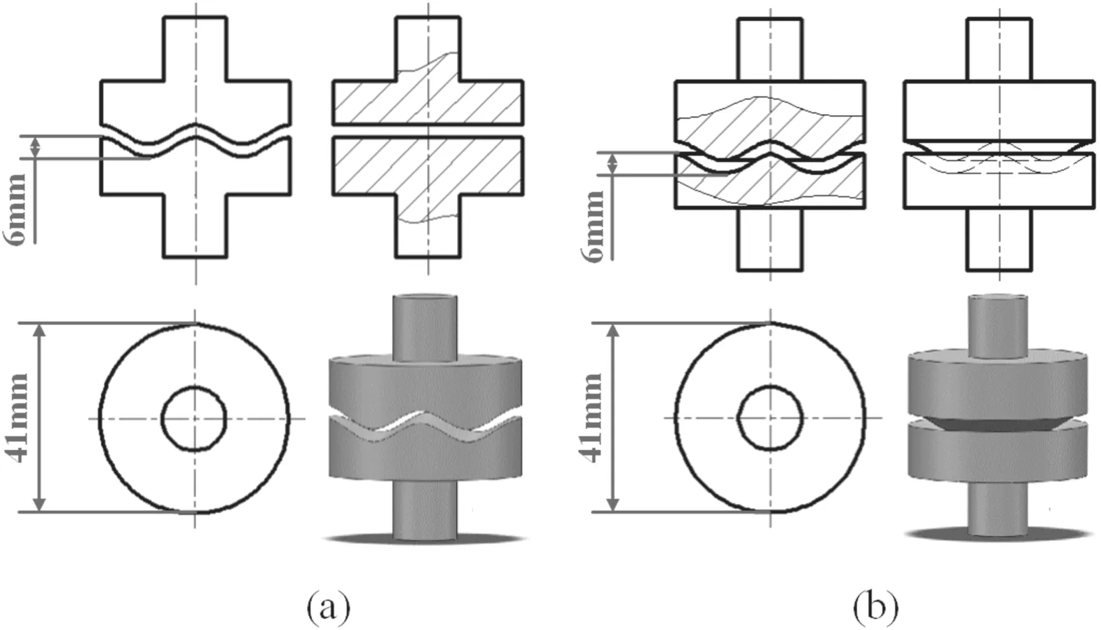
Figure 2.(a) Ruled curved contact, (b) revolute curved contact.

Table 1.Parameters of the contacts.
As shown in figure 3(a), the electrode structure of a sinusoidal curved surface effectively lightened the trend of the arc plasma moving towards the outside of the electrodes,compared with the butt contact.However,the ultimate effects were different between the ruled curved contact and the revolute curved contact.During the arcing period of these two types of sinusoidal curved contact, the main arc column area was almost between the electrodes,and there were not a large number of cathode spots on the side or back of the electrode.At time t1, the gap distance reached 3 mm, a large current flowed into the gap of the contacts. Between t2and t5, the vacuum arcs were in the expansion mode for the two contacts.During this stage, as the current amplitude increased, new cathode spots appeared in the arc root area and the arc column expanded all around from the starting point.However,the arc voltage of the revolute curved contact started to exhibit highfrequency noise at time t2and the arc voltage reached a peak value of 60.2 V.In comparison there was no obvious voltage noise for the ruled curved contact. At time t4, the arc voltage reached a peak value of 44.5 V.From t5to t8,the arcs were in the diffusion mode for these two types of contact as the cathode spots stopped expanding and the brightness of the arc column gradually weakened.As shown in figure 3(b),the arc voltage of the ruled curved contact is smoother during the current cycle than that of the butt contact or the revolute curved contact.
4. Characteristics of arc voltage
The arc voltages are shown in figure 4 at the peak current values of 7.5 and 12.5 kA from 360 to 800 Hz. It is evident that most of the arc voltages of the ruled curved contact are lower than those of the butt contact and the revolute curved contact during the current cycle.In addition,compared to the butt contact and the revolute curved contact, the arc voltages of the ruled curved contact were smoother at high frequency and large current.
When a current of 12.5 kA was interrupted at 585, 660 and 800 Hz,high-frequency voltage noise appeared in the arc voltage of the butt contact and the revolute curved contacts,while the arc voltages of the ruled curved contact were always smooth, without high-frequency noise.
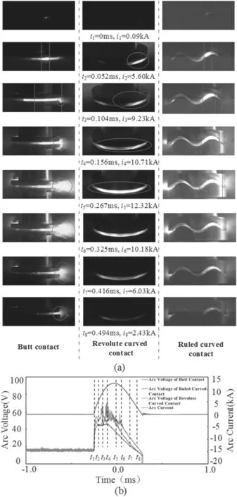
Figure 3.(a)The vacuum arc appearance and(b)voltage and current waveforms of arc for the sinusoidal curved contacts and the butt contact at 800 Hz, 12.5 kA peak current.
As shown in figure 5, the peak arc voltages of the ruled curved contact are lower than those of the butt contact and the revolute curved contact when peak currents of 5-15 kA are interrupted at 360-800 Hz. Owing to the dispersion and uncertainty of the voltage noise at a higher current amplitude and frequency, the arc voltage peak of the butt contact and the revolute curved contact appeared as an obvious increase as the peak value and frequency of the interrupting current increased.However, the arc voltage peak of the ruled curved contact exhibited a linear growth as the frequency and the current increased, which was consistent with a previous report [12].

Figure 4.Arc voltages of sinusoidal curved contacts and butt contact when peak currents of 7.5 and 12.5 kA are interrupted at 360-800 Hz.
5. Condensation and composition of arc products
During the arcing time, the plasma, metal vapor and liquid droplets generated by the electrodes deposited on the inner wall of the insulating shell of the vacuum arc extinguishing chamber. At 360-800 Hz and current of 5-15 kA, the same current interrupting tests were conducted for the three types of contacts, and each contact was tested for 125 times.
The shielding covers of the vacuum arc extinguishing chamber were removed so that the arc products could be directly deposited onto the inner wall of the glass cover.Microscopic images of the inner wall of the glass cover are shown in figure 6.These images indicate that there are a large number of condensed metal droplets on the inner wall of the butt contact, and the maximum diameter of the droplets observed is approximately 9 μm. In contrast, there are fewer metal droplets on the inner wall for the revolute curved contacts and the ruled curved contact, and the maximum diameter of droplets is smaller than 2 μm. These results are consistent with the behavior of the vacuum arc for these three contacts in figure 3(a).
The results of the composition analysis of the condensed metal droplets on the glass inner wall are shown in figure 7,and the proportion of W indicates that the anode vaporization of the ruled curved contact is lower than that of the butt contact and the revolute curved contacts. The surface of the revolute curved contacts had a significant influence on the diffusion of plasma, and it did not take full advantage of the contact surface, which led to heavier vaporization and ablation for the anode.
6. Arc energy, anode ablation and interrupting capacity
The energy that flows into the gap in arcing time has a significant influence on the interrupting capacity, the degree of ablation of the contact surface and the service life of the switch. This energy of the vacuum arc during the half-circle can be expressed as follows:

where Ehalfrepresents the arc ignition energy in the vacuum arc for half-cycle period, U(t) represents the arc voltage, I(t)represents the arc current and T represents the current cycle.Equation(1)is used to obtain the half-cycle arc energy of the three types of contact at 360-800 Hz and a current of 5-15 kA, and the results are shown in figure 8.
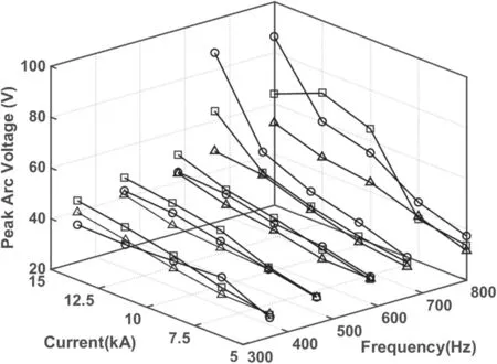
Figure 5.Peak arc voltages for sinusoidal curved contacts and butt contact when peak currents of 5-15 kA are interrupted at 360-800 Hz.

Figure 6.Glass inner wall of the sinusoidal curved contacts and the butt contact after large current interrupting experiment.
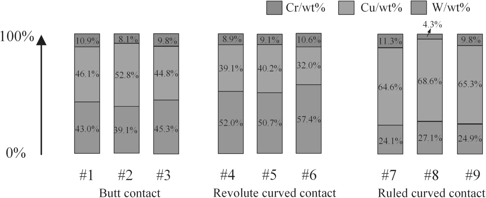
Figure 7.Composition analysis of the metal droplets on the glass cover inner wall (Anode: CuW80, Cathode: CuCr25).
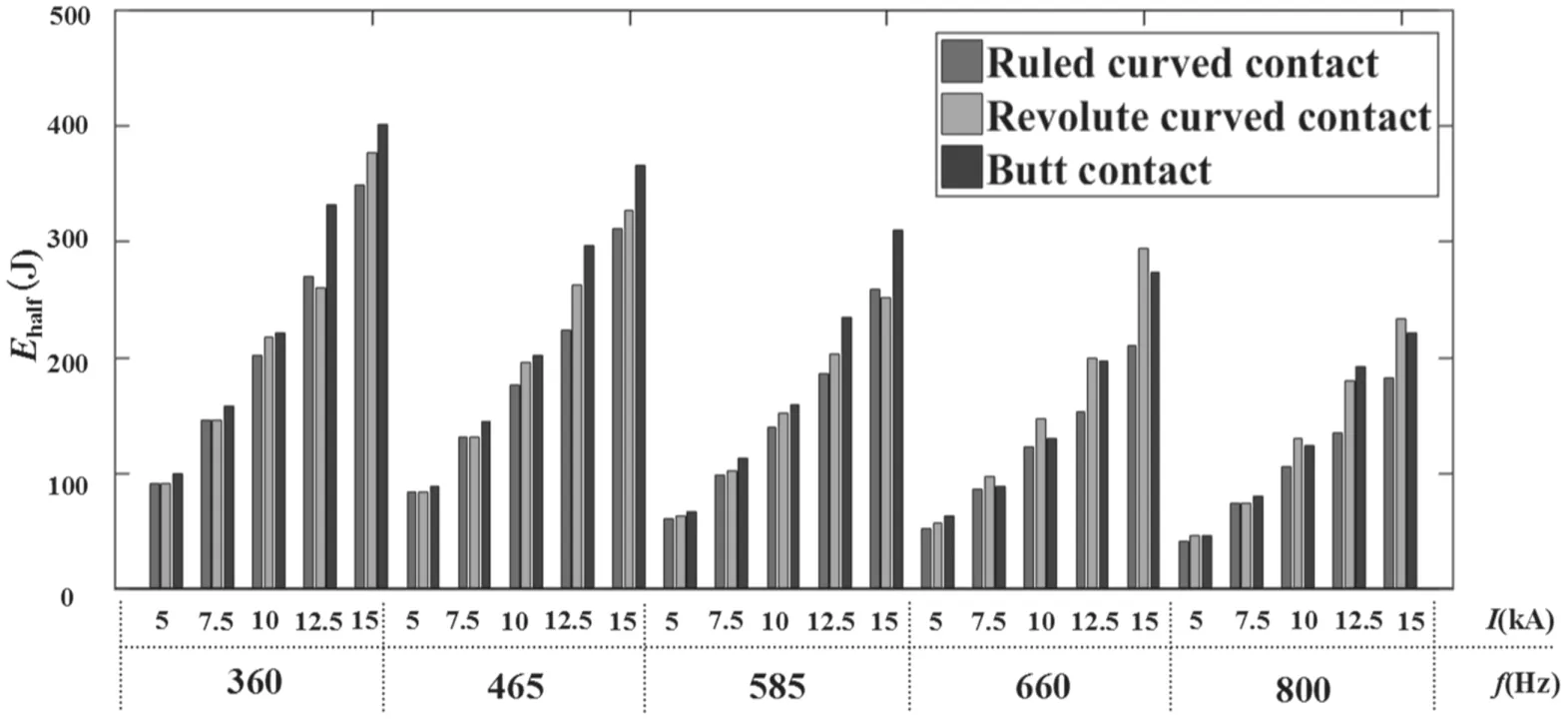
Figure 8.Arc energy for the sinusoidal curved contacts and the butt contact when peak currents of 5-15 kA are interrupted at 360-800 Hz.
As shown in figure 6, the value of the ruled curved contact was mostly lower than that of the butt contact and the revolute curved contact when the same current was interrupted.These phenomena became significant as the amplitude and frequency of the currents increased.
Based on curve fitting, the relationship between the arc energy of the three types of contacts used in this investigation,and the amplitude and frequency of interrupting current is obtained as follows:

where Ehalf*is the half-cycle arc energy,unit J;Ipis the peak value of the interrupting current,unit kA;f is the interrupting current frequency, unit Hz; A is 1.389, B is 0.7685, and K is an undetermined coefficient which is influenced by the contact distance, the structure and material of the electrode and other factors. For ruled curved contact, Kruledcurvedis 756.6 and the correlation coefficient R2for curve fitting is 0.979.For the revolute curved contact, Krevolutecurvedis 807.5, and the correlation coefficient R2for curve fitting is 0.973.For the butt contact, Kbuttis 910.4 and the correlation coefficient R2for curve fitting is 0.984.The results show that the arc energy is positively correlated with the current amplitude and is negatively correlated with the current frequency. In addition,the value of K of the ruled curved contact is smaller than that of the revolute curved contact and the butt contact.
Figure 9 demonstrates the surface ablation of anode for the sinusoidal curved contacts and the butt contact after interrupting the same large current.The ablation of anode for the butt contact and the revolute curved contact is relatively significant. There are pits and bulges on the edge of the butt contacts. Moreover, there are obvious pits and bulges on the edge and the center of the revolute curved contact. By contrast, the ablation area of the ruled curved contact is welldistributed, and its surface is smoother without obvious pits and bulges. The degree of anode ablation fits in with the arc energy of these three types of contacts shown in figure 9.
The limit interrupting currents of the three types of contacts at 360-800 Hz are shown in figure 10. The results show that the ruled curved contact has a greater interrupting capacity than the butt contact and the revolute curved contact at the same experimental setup.
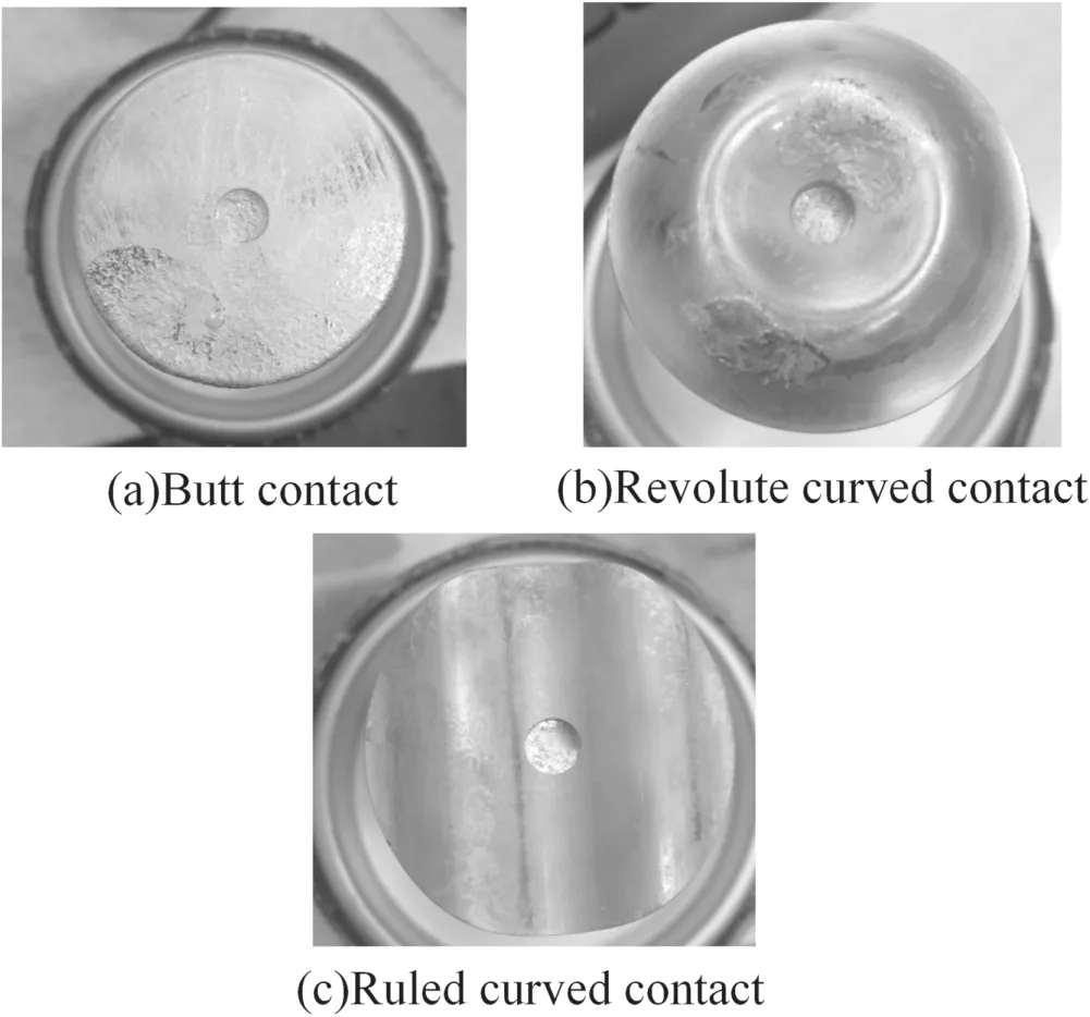
Figure 9.Anode contact of sinusoidal curved contacts and butt contact after high current interrupting experiment.
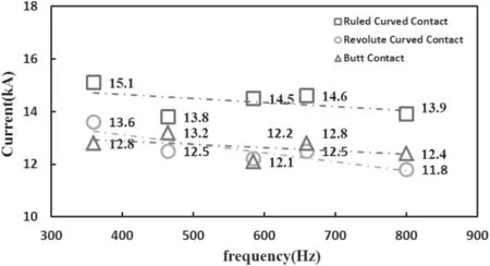
Figure 10.Limit interrupting current of sinusoidal curved contacts and butt contact.
7. Discussion
7.1. Reasons for the occurrence of arc voltage noise for the butt contact and the revolute curved contact
For the butt contact, it can be seen that the cathode spots on the butt contact tended to move towards the edge of the contact or even on the back of the contact as the arc column increased at large current in figure 3. A large number of cathode spots on the edge and back of the contact constantly produced, extinguished and split, which caused irregular motion paths for the plasma and huge changes in the arc resistance, so that the arc voltage became noisy during the current cycle. For the revolute curved contact, although the curved structure severely handicapped the observation of the arc, the extensive molten pools on the anode surface in figure 7 and the high proportion of W of the metal droplets on the glass cover inner wall in figure 10 implied the strong appearance of anode jets. Some workers found that when an anode jet struck the cathode and met a cathode jet through the gap, the arc voltage increased and became noisy [21, 22]. At the gap length of 3 mm, the shortest distance between the anode and the cathode will be even smaller than 3 mm as a result of the revolute curved structure, and the anode jet can easily have an effect on the arc voltage as the current increased.
The maintenance of arc voltage noise is caused by large nonstabilities and nonuniformities of the plasma in the contact space. As the current frequency increases, the discharge development at large di/dt needs a fast radial expansion of cathode spots, which will probably cause the unstable phenomena in the vacuum arc discharge [23]. It is one of the reasons why the voltage noise of the butt contact and revolute curved contact became more significant as the frequency of current increased.
7.2. Reasons for the difference in interrupting capacity among the three types of contacts
For the butt contact,as the cathode spots moved to the edge or back of the contact,the gap plasma diffused to the outside of the gap as shown in figure 3(a), which caused a plasma loss and a strong instability of the vacuum arc,and the plasma loss led to high arc energy to maintain the arc discharge. Moreover, the high arc energy and the instability of the arc discharge caused serious erosion at the edge of anode as shown in figure 9(a), which would highly possibly give rise to arc restriking [14]. For the revolute curved contact, the curved surface lightened the movement of cathode spots towards the edge and reduced the plasma loss towards the gap.However,excessive restriction of plasma diffusion led to local high plasma density and strong anode vaporization as shown in figure 9(b), which also led to instability of plasma state and serious ablation with high arc voltage and arc energy.Moreover, this restriction effect may also prevent the postzero residual arc column plasma from diffusing which was not conducive to the post-arc dielectric recovery.For the ruled curved contact, as the restriction of its curved surface was appropriately beneficial,the cathode spots were able to finish the expansion on the surface of contact. The ablation by the arc was distributed evenly on the surface as shown in figure 9(c),and the post-zero residual metal vapor and plasma can be easily absorbed by the increased surface.
Thus the experimental evidence seems to indicate that simply increasing the surface area by curving the surface of contact does not necessarily improve its interrupting capacity.Only when the curved structure properly is harmonious with the movement of cathode spots and the diffusion of plasma,it will not cause the opposite effect, especially at short gap distance. The most likely reason for the difference effects between the two types of curved contact is that the surface of the revolute curved contact is curved from center to all sides,resulting in the difficulty in expanding for cathode spots in arcing time, while the ruled curved contact is flat in one direction, which provides a favorable condition for the expansion of cathode spots and the diffusion of plasma.
8. Conclusions
In this paper, properties of vacuum arc on the new two types of sinusoidal curved contact proposed and the butt contact at different currents (5-15 kA) and frequencies (360-800 Hz)have been studied. The following conclusions can be drawn:
(1) The ruled curved contact has a huge application potentiality for the aircraft intermediate-frequency power supply system because of its low arc energy,low arc voltage, light ablation on the surface of the anode contact and high interrupting capacity.
(2) The cathode spots moving on the edge and back of the contact are the main cause of the arc voltage noise for the butt contact. The sinusoidal curved contact structures designed in this investigation restrict the movement for cathode spots towards the edge of the contact,and the strong anode vaporization caused by an excessive restriction on the revolute ruled contact is the main reason for the arc voltage noise.
(3) The correlation of the arc energy with the amplitude and the frequency of the current is achieved for the three types of contacts. Due to the plasma loss on the butt contact or the strong anode vaporization,the arc energy of the butt contact or revolute curved contact is higher than that of the ruled curved contact.
(4) Analysis suggests that simply increasing the surface area by curving the surface of contact at a certain diameter does not necessarily improve its interrupting capacity. A proper degree of the restriction on the cathode spots should be considered for the design of the curved contact structure.
Acknowledgments
This work is supported by National Natural Science Foundation of China(Nos.51677002 and 51937004),Civil Aircraft Special Research and Technology Research Project (MJ-2017-S-46),State Key Laboratory of Reliability and Intelligence of Electrical Equipment(No.EERIKF004),Hebei University of Technology and selected from the 1st International Symposium on Insulation and Discharge Computation for Power Equipment.
 Plasma Science and Technology2020年2期
- Plasma Science and Technology的其它文章
- Analysis of the characteristics of the plasma of an RF driven ion source for a neutral beam injector
- Synthesis of vertical graphene nanowalls by cracking n-dodecane using RF inductivelycoupled plasma-enhanced chemical vapor deposition
- Application of persulfate in low-temperature atmospheric-pressure plasma jet for enhanced treatment of onychomycosis
- Magnetic field enhanced radio frequency ion source and its application for Siincorporation diamond-like carbon film preparation
- Microwave frequency downshift in the timevarying collision plasma
- Comparison of Reynolds average Navier-Stokes turbulence models in numerical simulations of the DC arc plasma torch
