Characteristics of the propagation of partial discharge ultrasonic signals on a transformer wall based on Sagnac interference
Jun JIANG (江軍), Kai WANG (王凱), Xuerui WU (吳雪瑞), Guoming MA(馬國明) and Chaohai ZHANG (張潮海)
1 Jiangsu Key Laboratory of New Energy Generation and Power Conversion, Nanjing University of Aeronautics and Astronautics, Nanjing 211106, People’s Republic of China
2 Department of Electrical&Electronic Engineering,School of Engineering,The University of Manchester,Manchester M13 9PL, United Kingdom
3 State Key Laboratory of Alternate Electrical Power System with Renewable Energy Sources,North China Electric Power University, Beijing 102206, People’s Republic of China
Abstract The acoustic emission (AE) method has been widely recognized for the detection of incipient insulation fault phenomenon (partial discharge, PD) in power transformers, nevertheless, the installation and placement of AE sensors should be taken into full consideration. In this manuscript,a three-dimensional multiphysics model was established and simulated to research the characteristics of the propagation in the transformer wall. Furthermore, a piezoelectric transducer was used to detect PD ultrasonic signals and verify the simulation results in the laboratory. To ensure the accuracy of the detection, an optical fiber sensor based on the Sagnac interference principle was designed and adopted. The variation of the amplitude of the ultrasonic signal with distance reveals the characteristics of the ultrasonic signal propagating in the transformer wall.The distribution of sound pressure on the upper and lower surfaces of the simulation model proved that ultrasonic waves propagate in the form of symmetrical Lamb waves in the transformer wall.Moreover, the amplitude of the AE attenuates due to absorption and refraction loss, and local fluctuations on account of acoustic interference. Thus, a stable signal detected by an AE sensor does not represent the absence of PD in a transformer.To improve the reliability of AE detection,it is proposed in this manuscript that repeated movement of the AE sensor is necessary to obtain a suitable measurement position.Similarly,it is necessary to adjust the position of the AE sensor in order to locate the PD source well. In addition, this study is expected to provide a theoretical analysis and a fiber sensor to address the problem of sensor placement in AE detection.
Keywords: partial discharge, power transformer, ultrasonic detection, optical fiber, Sagnac interference
1. Introduction
Power transformers are one of the core parts of the power grid and their operational reliability is directly related to the safety and stability of the power system. Partial discharge(PD) detection is an important indicator for the healthy evaluation of power transformers [1]. To reduce and avoid severe failures from the insulation components in time, various on-line PD monitoring systems are widely developed to support corrective maintenance for power transformers, especially with the trend of condition-based maintenance [2].
Several techniques have been generally utilized to detect PD, such as high frequency current (HFCT) [3], ultra high frequency (UHF), etc [4]. HFCT (frequency ranges from hundreds of kHz to dozens of MHz) and UHF (frequency ranges from 300-3000 MHz) based on the law of electromagnetic induction have relatively high sensitivity and easy installation for on-line monitoring of PD[5-7].However,the electrical sensor is vulnerable to the complex electromagnetic interference(EMI)in the wide band of frequency onsite.With regard to the detection of insulation faults in power transformers, the acoustic emission (AE) method has been widely recognized and applied due to its advantages of anti-electromagnetic interference and ability of locating the position of the PD. Therefore, it is widely recognized in the field of detection of PD and is combined with other electrical sensors to improve the accuracy and reliability of measurement[2, 8, 9]. However, due to high attenuation of the AE signals while traveling from the PD source to the AE sensor, the sensitivity and locating accuracy of using AE sensors for PD detection cannot be guaranteed [10, 11].
AE sensors are usually installed on the transformer wall.Thus the transformer wall is an important medium for PD ultrasonic detection, but it is often overlooked. In order to eliminate the influence of signal attenuation on detection results,placement of the AE sensor inside the transformer has been carried out as well. Some researchers have obtained a sensor based on a a new concept of combining an AE sensor with other detection methods. It is implemented with the AE sensor inside the transformer tank [12, 13]. However, most substations still rely on a traditional AE sensor installed outside to detect PD ultrasonic. Thus, it is necessary to improve the sensitivity of PD detection with an alternative approach. Various de-noised techniques and artificial neural networks/artificial intelligence algorithms have been put forward to enhance the effectiveness [14, 15]. However, it is more important to investigate the characteristics of the ultrasonic propagation of the PD to reduce errors in the process of detection. It includes the characteristics of the ultrasonic propagation in insulation oil,influence of internal components of transformers on ultrasonic signals,and the law of propagation of ultrasonic inside transformers [16-19]. The literature [20] has proposed a mathematical model to show that a PD ultrasonic signal propagates in the form of a spherical wave in insulation oil. According to the work by Akumu et al [21], there are multiple transmission paths of a PD in a transformer due to iron cores and other devices.In this way,the path affects the arrival time of the PD peak with the consideration of both the internal components and transformer oil. Moreover, the attenuation and refraction of ultrasonic waves in the transformer easily cause aliasing wave phenomenon and inaccurate position localization.Xie et al [22] carried out research on and an analysis of the influence of attenuation and refraction of ultrasonic waves.However, the current study focuses on the ultrasonic characteristics of the PD that are just located inside of the transformer.The influence of the transformer wall is always ignored and it will lead to probable detection failure. It is necessary to illuminate the characteristics of the propagation in the transformer wall since AE sensors are always installed on it.It is worth mentioning that the post-processing part of the PT sensor is not fully immune to EMI,and optical sensing technology has better anti-electromagnetic interference performance compared to PT[23-26].Thus,it is a good way to study the the characteristics of the propagation of PD ultrasound by fiber optic sensing.
To improve the accuracy of the PD ultrasonic location and sensitivity of detection, this paper focuses on the characteristics of the propagation in the transformer wall. By setting different probes to investigate the relationship between the amplitude and distance of the ultrasonic signal inside the transformer shell, the ultrasonic propagation mode of the transformer wall is verified. In addition, PT and Sagnac interference are adopted in the laboratory and the research process is the same as that of the simulation step. The characteristics of the spreading obtained by various ways are compared and analyzed afterwards.
2. Ultrasonic simulation model of PD
On the one hand, it is assumed that the medium is ideal,continuous, uniform, and has no energy loss. On the other hand,the velocity field of sound has no eddy current and loss inside the system was assumed. The momentum theorem demonstrates thatΔ × =v 0 and the wave equation can be obtained when the sound source size is smaller than space scale:

where P is the effective value of the acoustic pressure in pascal (Pa), c is the speed of sound (m s?1). The wave equation has been simplified as a part that only contains time variables and spatial variables. After separating the equation and variables,a Helmholtz equation can be obtained,and k is assumed to be a constant:

The solution of the acoustic wave equation is transformed into a Helmholtz equation according to above analysis.
A simulation model is constructed in this work to analyze the characteristics of the ultrasound using COMSOL Multiphysics software. There are three kinds of common domain boundaries at an acoustic module, including a sound hard boundary, a particle normal velocity boundary, and an impedance boundary. These boundary conditions are expressed as follows: n is defined as the outward oriented normal vector andρ0is the fluid/solid density.
Sound hard boundary:

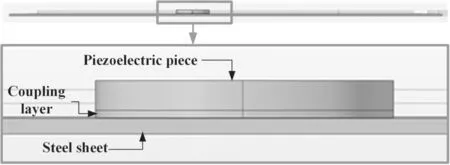
Figure 1.Composition of the model and the setting of the materials.
Particle normal boundary:

Impedance boundary:

Because normal acceleration on an outer wall is assumed to be zero, sound hard boundaries are often used to simulate walls, enclosures, etc, and the sound hard boundary is set as the transformer wall in this manuscript. The impedance boundary can be equivalent to simple resistance-inductancecapacitance(RLC)circuit models and the simulated boundary conditions of the piezo.
The electromagnetic oscillation process, mechanical action, and sound propagation have similarities in mathematical expression. Therefore, the amplitudes of the PD electrical pulse signal and mechanical vibration can be mutually equivalent. The amplitude of the ultrasound generated by the PD is proportional to the amount of discharge when the oscillation of the PD is ignored. The vibration displacement caused by PD ultrasonic signals appears as an underdamped movement,which can be represented as the attenuation pulse signal of exponential oscillation. The function expression is

The vibration amplitude A (μm) is caused by PD electrical pulse,f is frequency of PD oscillation (Hz),andτ is the time constant.
For studying the characteristics of the propagation of the PD ultrasonic signal inside the transformer wall, a simplified geometric model is built to establish an experimental platform conveniently.Firstly,a 3D sheet of 50×50 × 0.2 cm3and a simplified piezoelectric piece model with a radius of 2 cm and a height of 0.4 cm are established. When thinking about the actual experiment, a coupling layer is provided at the contact portion between the piezoelectric piece and the sheet. The coupling layer is represented by a cylinder with a radius of 2 cm and a height of 0.1 cm, and is shown in figure 1.
The sheet is defined as steel material. It is in accordance with the material properties of the transformer wall, which is conducive to subsequent experimental analysis and research.The coupling layer is made of Vaseline to improve the transmission efficiency of the acoustic energy between the piezoelectric piece and the steel sheet. Moreover, Vaseline also prevents the surface of the steel sheet from being damaged by the piezoelectric sheet in practice. The piezoelectric piece is made of lead zirconate titanate(PZT-4)in the COMSOL material library. The material parameters of steel,Vaseline, and PZT-4 are shown in table 1. Among them,sound speed is the composite speed of the ultrasound signal propagating through the dielectric material under standard conditions.
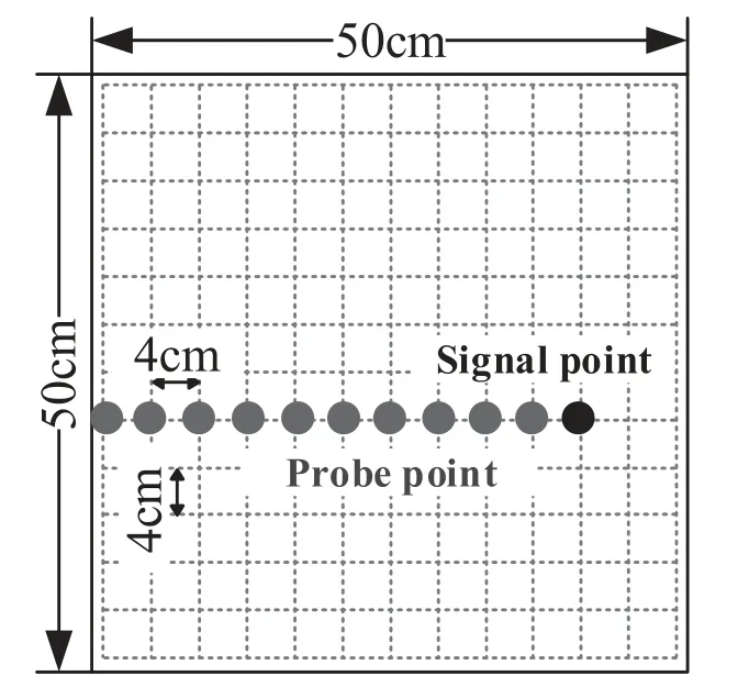
Figure 2.Illustration of the layout of the signal point and probe points.
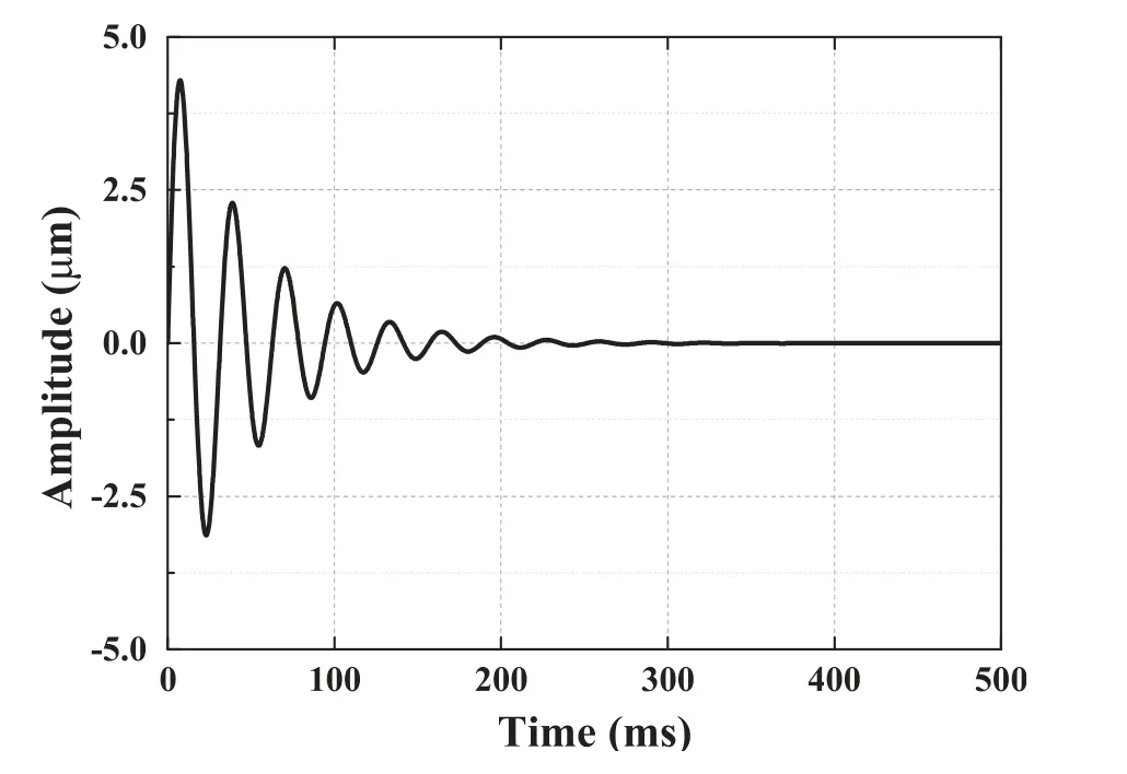
Figure 3.PD excitation signal of an exponential decay pulse waveform.

Table 1.Material parameters of different components of the model.
In order to study the variation of the amplitude of the ultrasonic signals at different distances while considering the convenience of the specific experimental arrangement and the size of steel sheet, 11 probe points were placed in the experiment. Each of the two-probe points are separated by 4 cm and different probe points detect simulated PD ultrasonic signals simultaneously. The probe expressed as a black point is located below the piezoelectric piece to detect the original signal waveform. The arrangement positions of the probe point and PD signal source are shown in figure 2.
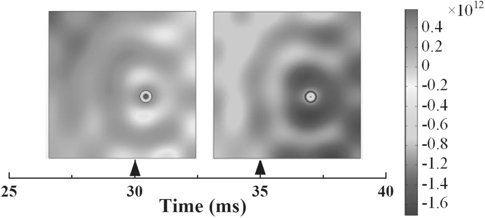
Figure 4.Distribution of the sound pressure on the surface of the steel sheet at different times.
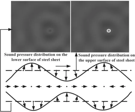
Figure 5.Distribution of the the sound pressure on the surface of the steel sheet and the verification of the propagation mode.
For simulating the actual characteristics of the propagation of the PD ultrasonic signal, equation (6) is set in the opposite direction of the z-axis on a piezoelectric piece surface. Amplitude A is 5 μm and frequency f is 20 kHz. The excitation signal waveform is shown in figure 3.
The piezoelectric acoustic transient module is used to research the characteristics of the propagation of the simulated PD ultrasonic signals in a steel sheet. The frequency is changed from 20-100 kHz because the PD ultrasonic signal frequency in the transformer is usually in the range of 20-100 kHz. To ensure reliability, the experiments were repeated five times under different conditions.
3. Analysis of the simulation results
In view of the actual detection experiment, the attenuation pulse signal of exponential oscillation is replaced by a sinusoidal signal, which makes it easier to observe experimental phenomenon and reveals the characteristics of the propagation of an ultrasonic wave inside a steel sheet. Figure 4 shows the distribution of the sound pressure on the surface of the steel.
The red part indicates that the particle moves in the positive direction of the direction of the propagation. The deeper the red is, the larger the vibration amplitude of the particle in the positive direction is. In the blue part, it is demonstrated that the particle moves in the opposite direction of the direction of the propagation,and the deeper the blue is,the stronger the vibration amplitude of the particle in the opposite direction is.
The surface wave propagates in the form of Lamb wave,which is usually propagated in a thin plate and is generated by the superposition of a transverse wave and a longitudinal wave.The propagation modes of Lamb waves mainly include the symmetric mode and anti-symmetric mode. According to the sound pressure diagram of the upper surface and lower surfaces of the steel sheet,when the excitation signal is a sine wave, the ultrasonic wave propagates in the form of a symmetric mode Lamb wave inside the steel sheet, and is shown in figure 5.
To reflect the variation in amplitude with distance,waveforms of a simulated ultrasonic signal received by different probe points are shown in figure 6.The sound pressure amplitude of the ultrasonic signal has a discrepancy at different distances, and the overall trend of the amplitude is inversely proportional to distance. The reason is that the cumulative energy per unit area gradually decreases with distance.At the same time,refraction and absorption occur on the surface of the sheet and result in a partial energy loss.Therefore, the farther the propagation distance is, the smaller the amplitude of the received ultrasonic signal is.
In order to reflect the variation of the amplitude with distance more accurately, the characteristics of the amplitude and distance can be obtained by changing the frequency and conducting multiple experiments, as shown in figure 7.
The amplitude of the ultrasonic signal at different frequencies tends to decrease, which is similar to the characteristics of the variation of the amplitude at the attenuation pulse signal of exponential oscillation. However, due to the interference of ultrasonic propagation on the surface of the steel sheet in the process of decline, the sound pressure amplitude has some rising process. The sound pressure reaches the maximum value when two ultrasonic vibrations with the same direction, frequency, and phase superimpose;when ultrasonic vibrations have the same direction and frequency, but the phase is opposite, sound waves are counteracted and then the sound pressure appears at minimum points.
4. Experimental establishment and verification
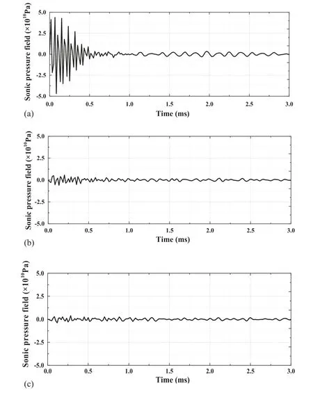
Figure 6.PD waveforms detected at different locations. (a) PD source, (b) 8 cm from the PD source, (c) 16 cm from the PD source.
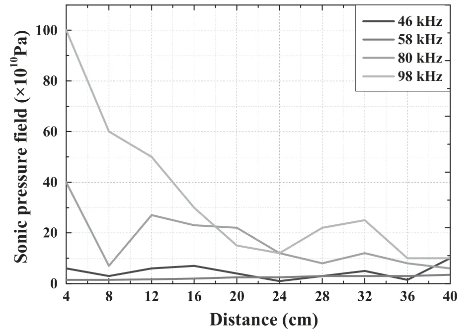
Figure 7.Simulation of the characteristics of the amplitude and distance at different frequencies.
Since the optical interference method is based on the Sagnac interference principle it can detect the weak vibration caused by the PD and is consistent with the principle of the detection of an AE sensor.To ensure the reliability of the experiment,a Sagnac optical sensor and AE sensor were simultaneously used to detect the ultrasonic signals caused by the PD. The basic principle of a Sagnac optical detection system is shown in figure 8.Light from the light source is split into two beams by a coupler, which are respectively transmitted in the forward and anticlockwise directions of the fiber coil.After two beams of light have been transmitted in the coil,they return to the coupler and interference phenomenon occurs. The main part of the Sagnac system is a closed fiber coil. If there is no external disturbance, two beams have the same phase; when there is an angular velocity along the normal direction of the coil, two beams produce a Sagnac phase difference with a change in the intensity of the corresponding interference signal. By detecting the intensity of the light of the interference signal,the magnitude of the external angular velocity can be known, thereby the external vibration intensity and frequency are explored.
To verify the effectiveness of the AE sensor and a fiber sensing probe, a PD model is built as shown in figure 9. The needle-plate PD model is chosen on account of its universality and typicality. The distance between the needle and the plate is 1 cm,and the interval is filled with air.A needle electrode is connected to a high voltage input, and the plate electrode is grounded.The high voltage amplifier and signal generator are composed of a high voltage signal input with an adjustable voltage level.The output voltage of the high voltage amplifier is 6.3 kV and the apparent charge of the PD is 500 pC.
The results of the PD detection using an AE sensor and optical fiber structure are shown in figure 10.It is shown that the AE sensor and optical fiber not only are effective in actual PD detection, but can also be used for research on the characteristics of the ultrasonic propagation of the PD.
However, the PD signal often appears intermittently in actual detection. At the same time,for the sake of facilitating the statistics of the amplitude of ultrasound, a standard sinusoidal signal was used to replace the PD signal for detection. In this manuscript, R15α and R3α (Physical Acoustics Corporation, USA) are used as the ultrasonic signal-transmitting terminal and signal-receiving terminal,respectively. Since the frequency response range of R3α is narrower than that of R15α, and to improve the accuracy of the detection result, R3α was used as signal-receiving terminal. A C-band broadband light source was selected as the optical signal source to reduce detection noise. Trek’s oscilloscope,model MDO3034,has a sampling rate of 2.5 GS s?1,and it meets the experimental requirements.In order to protect the AE sensor,Vaseline was chosen as couplant material,and aa 50× 50× 0.2 cm3steel sheet was customized as a propagation medium.For allowing the ultrasonic signal be more clear, the steel sheet was suspended by brackets. The signal generator generates a sinusoidal signal which excites the AE sensor. Meanwhile its frequency is consistent with the simulation frequency. The following ultrasonic wave is transmitted to the steel sheet through a coupling agent layer.Multiple refractions and reflections were generated in the steel sheet medium. Finally, the receiving probe receives the ultrasonic signal and connects with the oscilloscope for displaying, recording, and processing experimental data. The experimental scheme is shown in figure 11.
The AE probe R3α and sensing optical fiber probe were placed at simulated probe point position.AE probe R15α was placed at signal source. Since simultaneous multi-point ultrasonic signal detection is difficult to realize in actual detection,a grid was drawn on the surface of the teel plate and the sensing probes were moved.
After the experimental platform is built,the output signal from the signal generator is constant with the changed positions of the ultrasonic probe.Further this research changes the frequency of the output signal to study whether the attenuation of the ultrasonic signal inside the steel plate at different frequencies is consistent,and the result is shown in figure 12.
It can be seen from figure 12 that the variation of the amplitude of the AE sensor and optical fiber sensor are basically the same as the simulations in the actual experiment.During the incidence of sound waves, a part of the energy is transmitted to the steel plate through a couplant layer and continues to propagate with incident direction. Because of absorption attenuation and scattering attenuation of energy,the overall variation trend decreases with the increase in the amplitude of the sound pressure.Another part of the energy is reflected by the surface of the steel sheet into the air medium.In addition, a small amount of energy spreads along the steel plate. According to interference phenomenon, a plurality of maximum and minimum values appear in the characteristics of the ultrasonic amplitude of the steel sheet.Figure 12 shows that there is a little difference between the actual experiment and the simulated measurement results at 36 and 40 cm. That is because the coupling agent was supplemented to protect to surface of the PT, which resulted in the thickness of the coupling agent layer not meeting the requirements of a control variable. The greater the thickness of the couplant layer, the farther the ultrasonic wave propagation distance is in this part,and the greater the absorption attenuation and scattering attenuation are. It further leads to the worsening of the coupling effect and the smaller amplitude of the ultrasonic signal received, which will cause some details to differ, but the overall trend remains the same.
5. Conclusion
Since the transformer wall is an important medium for internal PD and external detection,it is necessary to study the characteristics of the propagation of the ultrasonic signal generated by the PD in the transformer wall. On the basis of researching the amplitude of the waveform which was received from PT and Sagnac interference at different positions and comparing it with the simulation,the following conclusions can be obtained:
(1) The optical detection system based on the Sagnac interference principle is consistent with the stated parameters detected by traditional AE probes, and both of them are effective in PD detection.
(2) By comparing the distribution of sound pressure on the upper surface and lower surface of the simplified model simultaneously, the propagation mode of the ultrasonic wave inside the transformer wall is a symmetric(S-type) Lamb wave.
(3) As the distance increases, the cumulative energy per unit area of the wall gradually decreases, and the phenomenon of a large amount of energy refraction and absorption appears on the surface of the wall, which resuls in a partial energy loss.
(4) Due to interference phenomenon in the process of sound wave propagation, when two ultrasonic vibrations have the same directions,frequencies,and phases,sound waves are superimposed so that pressure of the sound generates a maximum value point. Similarly, a plurality of minimum value points exist in sound waves.Thus, the characteristics of the AE amplitude fluctuate and decrease with the increased distance.

Figure 8.Sagnac interference structure to detect PD ultrasonic signals.

Figure 9.Experimental platform for ultrasonic detection of the real PD.
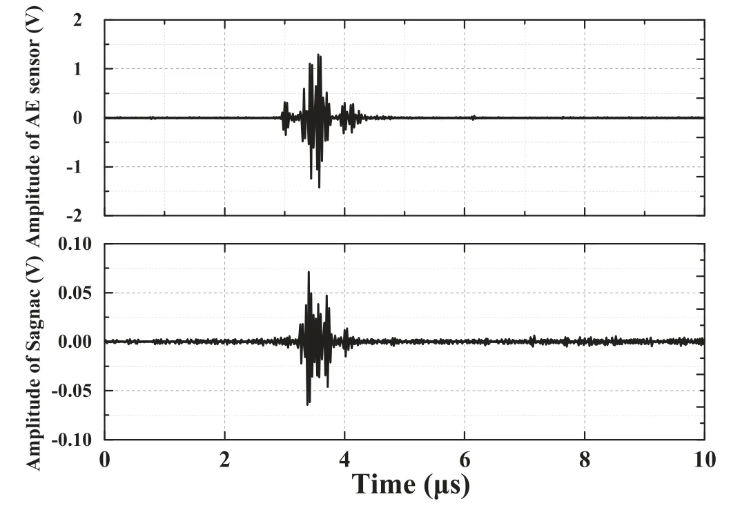
Figure 10.The actual PD signals received by an optical fiber sensing probe and a acoustic emission probe.
Acknowledgments

Figure 11.The experimental platform for the detection of PD ultrasound.
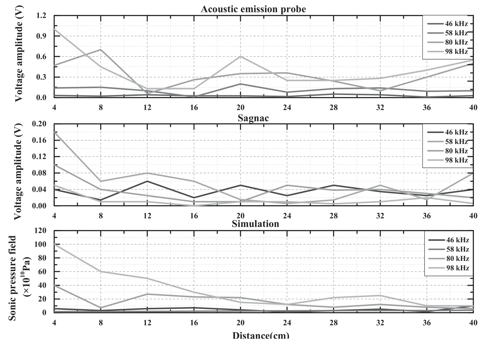
Figure 12.Actual characteristics of the detection and simulation amplitude.
This work is supported by National Natural Science Foundation of China (No. 51807088), the Natural Science Foundation of Jiangsu Province(No.BK20170786),the State Key Laboratory of Alternate Electrical Power System with Renewable Energy Sources (No. LAPS19010), Project funded by China Postdoctoral Science Foundation, the Fundamental Research Funds for the Central Universities (Nos.NS2018027,kfjj20190304),and the Jiangsu Planned Projects for Postdoctoral Research Funds. The authors gratefully acknowledge financial support from the China Scholarship Council (No. 201906835029).
 Plasma Science and Technology2020年2期
- Plasma Science and Technology的其它文章
- Analysis of the characteristics of the plasma of an RF driven ion source for a neutral beam injector
- Synthesis of vertical graphene nanowalls by cracking n-dodecane using RF inductivelycoupled plasma-enhanced chemical vapor deposition
- Application of persulfate in low-temperature atmospheric-pressure plasma jet for enhanced treatment of onychomycosis
- Magnetic field enhanced radio frequency ion source and its application for Siincorporation diamond-like carbon film preparation
- Microwave frequency downshift in the timevarying collision plasma
- Comparison of Reynolds average Navier-Stokes turbulence models in numerical simulations of the DC arc plasma torch
