Cooperative Relay Based on Exploiting Hybrid ARQ
Mingxuan Li,Jie Lin,Liang Zhong,,Mengting Wang,Wei Lv
1 China University of Geosciences School of Mechanical Engineering and Electronic Information,Department of Electronics and Information Engineering,Wuhan 430074,China
2 Air Force Early Warning Academy,Wuhan 430010,China
Abstract: In order to compensate the primary performance degradation,which is caused by the co-existing secondary communications or the heavy fading of primary link,a cooperative relay scheme is proposed in cognitive radio systems by taking advantage of the opportunities that are arisen by the primary ARQ(Automatic Repeat-reQuest) retransmission.With the help of this scheme,nontrivial relay assistances for the primary retransmission are achieved without initialization phase.The cooperation among secondary users provides additional spatial diversity to facilitate the primary transmission.This can be accomplished with an oblivious primary system and without assuming any non-causal information about the primary data.The scheme are further extended to the scenarios where multiple cognitive pairs exist.Performance analyses of the schemes are devised and the effectiveness is verified via simulations.
Keywords: cognitive radio; cooperative relay;ARQ; coexistence; outage probability
I.INTRODUCTION
Femtocell with cognitive functionality provides intelligent spectrum sharing and efficient spectrum utilization,which is promised to solve the spectrum shortage.With the notion of minimizing interference,the femtocell users (secondary users,SU) communicate simultaneously in the same spectrum,which is originally allocated to the existing marcocell users (primary users,PU).However,the primary transmission is malignly influenced by the co-existing secondary communications.Specifically,when the femtocell is deployed at the marcocell edge,it may introduce dead zone to the cell edge primary users in practical scenarios [1].
Ordinarily,primary compensation [2]and imposing strict constraints on the interference caused by SUs [3]are used to overcome the above problems in traditional Cognitive Radio(CR) networks.In overlay cognitive networks,where the secondary users are promised to have the knowledge of primary users’ codebooks and its messages,researches focus on performing encoding techniques to facilitate the primary transmission,such as: superposition encoding scheme [4],rate-splitting encoding technique [5],Dirty-Paper Coding (DPC)[6],etc.Additionally,when the Automatic Repeat-reQuest (ARQ) message of PU is available,an interference mitigation protocol has been proposed for SUs to increase the rate of the cognitive system and to reduce the interference during the primary retransmission by decoding the message of PU [7].However,the non-casual requirement of the PU’s codebooks and its signals for SUs may be problematic when implementing these techniques in practice.
On the other hand,in underlay cognitive networks,SUs need to restrict their average transmit power to concurrently transmit with PU,which limits secondary coverage area and potential secondary transmission rate [3][8].Many schemes have been proposed to use dedicated relay nodes for SUs to enhance the secondary communication [9].However,these relays cause additional deployment and maintenance costs to vendors of these networks.In conclusion,SU pairs work in a very conservative manner with the limitations on their maximum transmission power and secondary coverage.To ease these restrictions,an Interference Neutralization Relay (INR) scheme is proposed in this paper,which provides diversity gains to the PU’s retransmission without noncausal requirement of PU’s message.
Unlike the conventional relay schemes [13][14],the proposed scheme does not need the initialization phase to obtain or to decode the data of marcocell user.Conversely,the gains are reaped from the cooperation interference neutralization among femtocell users in the proposed scheme.As a result,the marcocell user’s diversity gains can be trade-off for a larger femtocell transmission power,which means that the femtocell user could have a better capacity potential and coverage performance under some pre-defined interference constraints.
As is well-known,each SU decodes its own desired signal and discards the rest of its received packet.It is worth noting that the discard part of the received packet,which is considered as “interference” to SUs,contains a noised copy of primary message (and some useless terms from other SUs if the number of SUs is bigger than one).In this paper,the proposed INR scheme reuses the noised copy of primary message to provide diversity gains to the PU’s retransmission without decoding primary message.In multiple SUs scenario,interference neutralization is introduced to neutralize the useless terms caused by other SUs in the “interference”.Interference neutralization is newly proposed by researchers to improve the capacity of multi-hop networks with coordinated precoder design [10][11][12].
The closed-form expressions of primary outage probability and the optimal relay power are derived.Then,numerical experiments are given to verify our claims.The simulation results indicate that the proposed relay scheme can decrease the primary outage probability significantly with both perfect channel state information (CSI) and partial primary CSI.
II.SYSTEM MODEL
We consider a retransmission-based two-tier network with entity pairs communicating concurrently with mutual interference.Figure 1 depicts the system model under consideration.The application in figure 1 will be detailed in section 4.The communication nodes,which include one primary transmitter-receiver pair with the stop-and-wait (SAW) ARQ and M secondary transmitter-receiver pairs,are all equipped with a single antenna.This ensures that INR can be easily implemented in both uplink and downlink transmission of femtocell users.
Rayleigh fading models are used in this paper as previous work [15][16],and channels are assumed to be static during one time block.dij,gijandhijare the distance,the amplitude of fading channel coefficient and the effective channel gain between transmitterjand receiveri.with path loss coefficient α andwhere theCN(0,1) means standard normal distribution.The subscriptpis reserved for PU,and other subscripts belong to SUs.
In addition,due to the fact that SUs are within the same network,SUs are assumed to have the knowledge of the instantaneous channel gains of secondary links with a possibly dedicated feedback channel.However,in a typical cognitive network,secondary network is not coordinated with the primary network and no dedicated feedback channel is deployed for SUs to obtain the instantaneous channel gains of the primary link.Fortunately,we will detail later that INR needs no instantaneous channel gains of PU to achieve the relay functionality with combining techniques,such as MRC employed at primary receiver.
Suppose that primary node PT transmits signalxp,where,with a fixed powerPpand primary data rateRpin transmission phase.Meantime,STjtransmit their signalswhere simultaneously with a fixed powerPs.
Therefore,the received signal at receiveriis given by:

whereniis the Additive White Gaussian Noise(AWGN) at receiveriwith the correlation matrix
Throughout this paper,we use outage probability performance to quantify the primary Quality of Service (QoS).The outage probability of PU is formulated as the following event (in an information-theoretic sense) [17]:

whereP{·} is the probability of an event.Notice that random variables (RVs)andfollow the exponential distributions.
Without loss of generality,it is assumed that the PU outage happens at time block b.The SU node (maybe ST or SR) ,which transmits the relaying signals,is called as the relaying node (R-node).The SU nodes that neutralize the interference,are called as neutralizing nodes (N-nodes).We de fine precodersvRandvNjfor R-node and jth N-node in INR,respectively.The subscripts ‘R’ and ‘N’ denote the R-node and N-node.
In this paper,INR scheme with one secondary pair is discussed first,then it is extended to the multiple secondary pair scenario.Additionally,since whether the SU can correctly decode its own message may affect the performance of our scheme,we have analyzed the performance for both perfectly decoded case and the imperfectly decoded case.
III.INTERFERENCE NEUTRALIZATION RELAY
In this section,we detail a cooperative relay scheme to facilitate the primary (marcocell)retransmission in terms of outage probability for the retransmission-based two-tier networks.Firstly,we discuss the scenario with one secondary pair and one primary pair.After that,the scheme with multiple secondary pair and one primary pair is discussed.
3.1 Single secondary pair
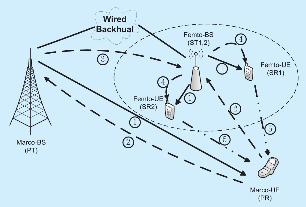
Fig.1.The system model under consideration and application.

Fig.2.Procedure of the cooperative relay scheme with 1 SU.
In this case,only one femtocell user is adja-cent to the marcocell user.If the secondary user has decoded the desired signal successfully,the relay scheme can be easily implemented by choosing SR as R-node,because no interference needs to be neutralized.
Here,we use “transmission phase” and“retransmission phase” to simplify the explanation of the corresponding SUs’ operations in different primary transmission states.In fact,INR is operated in “retransmission phase”only,and does not need additional phase as traditional two-phase relay schemes [13][14].We assume that the secondary transmitter has no non-causal knowledge of primary codebooks or signals except overhearing the ACK(Acknowledge) or NAK (Negative Acknowledge) signal transmitted by the primary receiver at the end of the transmission phase.
The scheme is detailed as following:
1) In time blockb,primary and secondary pairs communicate simultaneously.If the primary receiver PR successfully decodes,it emits an ACK.Upon hearing the ACK,SRs will decode the desired signals and discard the rest of the received packet.Then,all transmitters get ready to send a new message packet;
2) If the primary receiver is not able to decode,it will emit a NAK.This will be heard by the secondary receiver SR,who has decoded its own desired signal and stored the rest of the received packet (“interference”) in its buffer in time blockb.If successful,SR will send a “Clear to Relay” (CTR) signal to ST;
3) In blockb+1,the primary PT retransmits its packet.If furthermore a secondary CTR has been generated,SR transmits the “interference” as its relay signals simultaneously.The primary receiver combines the received codebooks from SR and PT.
The procedure is demonstrated in figure 2.The SUs’ state transitions depend on the hearted primary ARQ signals.When the primary outage happens,the PU emits a NAK.Upon overhearing the NAK,SUs will suspend their own communication and apply the proposed relay scheme in the next time blocks until an ACK is received.
The key features of this scheme are:
1) Primary and secondary transmissions are coexisting in transmission period;
2) Secondary pairs use INR in order to relay the primary signals during ARQ rounds of the primary without non-casual knowledge of the PU’s codebooks or messages;
3) Secondary pair reuses the “interference”,which contains a noised copy of primary message.Because that the primary user often works at high transmission power level,the power of primary message terms is much higher than the noise power contained in “interference”;
4) In case where secondary users failed to decode its own desired signals,the secondary pair will keep silent during ARQ rounds of primary.This is motivated by the idea that the operation of the secondary pair has costs(transmission power cost),therefore the secondary link should only be active when it can provide benefits to the primary retransmission,otherwise it should stay silent.
3.2 Multiple secondary pairs
In the above subsection,we detailed the proposed relay scheme which is used when the PU is embedded by one secondary pair.This scheme can be extended to theMSUs case with interference neutralization and relay selection criterion,whereM≥2.The main difference is that the interference neutralization is used to “neutralize” the useless terms,which comes from other STs in the relay signal.
In the retransmission phase,the primary source resends its signal again,one of the secondary destinations,which is chosen to be the R-node,sends the “interference” vector received in the transmission phase,and the other secondary nodes send their useful received signals to neutralize the resultant interference in the “interference” vector.By this way,the primary signal will be conveyed twice (by the primary source and one of the secondary destinations),which provides additional diversity gain to the primary retransmission.
Hereafter,we will give a detailed description of how INR works inMsecondary pairs’scenario.In the transmission phase,all SRs at-tempt to decode their own desired signals.The SU,whose receiver decode successfully,then joints the decoding set D,and the corresponding SRs becomes potential R-nodes.
It is worth noting that ifDis empty,i.e.,all SUs fail to decode their desired signals,the received signal of each SR is an affine combination of all transmit signals.Therefore,the secondary pairs will keep silent during ARQ rounds of primary.Otherwise,whenDis not empty,a relay selection criterion should be used to pick the most ef ficient relay node.
3.2.1 R-node selection
In general,the SR,which can provide the highest received signal power to PR,is viewed as the best R-node.However,without the instantaneous channel gains of primary links in retransmission phase,the received SINR at PR can not be obtained by SUs.More speci fically,the knowledge of received SINR at PR is noncausal to SRs in transmission phase.Here,we de fineγias the ef ficient parameter of SU i,which is the ratio of the useful relay power to the resultant interference power.
As mentioned in one SU scenario,theSUi(i∈Cm),which is chosen to be R-node,will send the “interference” signal ?i,which is received bySRiin transmission phase (time blockb).SRs,which can decode the respective STs’ signals successfully,belong to the potential relay setCm.The interference signal ?i,which is received bySRiat time blockb:

IfSRiis chosen to be the relay node,which is called R-node and use subscript ‘R’ to indicate,?iis reused by R-node at the retransmission period as relaying signals.Notice that the transmitted signalsxRandxNj,which belong to R-node andjth N-node respectively,can be expressed as:

Figure 3 illustrates the INR process in retransmission phase whenM=2.When ?iis resent by R-node in retransmission phase(time blockb+1),towards neutralizing the interference termxNin the received relay signals of PR,xN,which is assumed to be perfectly decoded by the N-node at transmission phase(time blockb),is reused at the retransmission phase (time blockb+1).Consequently,the effective channel gainshrof the relay link can be easily obtained as following:

Suppose that the relay transmission power isPr,the resultant interferenceIrwithin the relay signal is:

Therefore,given the candidate R-nodeSRiis selected,the corresponding ef ficient parameter by combining (5) and (6) as:

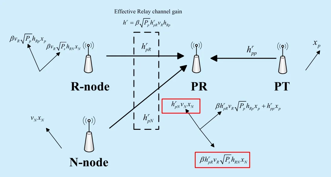
Fig.3.INR process in retransmission phase when M=2.
The more the resultant interferenceis,the more power cost the neutralization needs; the more the effective channel gainhris,the less power cost the relay signals need to guarantee a pre-defined primary outage threshold.Consequently,in order to implement INR,the best R-node,which has the maximumγi,should be selected to forward the message.Therefore,the best R-node selection criterion is given as:

where subscriptcdenotes the index of the best SU to be R-node.
It is worth pointing out that the efficient parameter is dependent on the channel gains and transmit power of the previous time block,thus each SU can calculate its own efficient parameter in current time block independently.When primary NAK signal is received,each SU can obtain its efficient parameter immediately.Hence,it is available to further develop best R-node selection algorithms in both centralized and distributed approaches.
3.2.2 Neutralization Precoder Design
The neutralization setNconsists of two sets: The setTmconsists of the transmitterswhose receivers failed to decode their desired signalsxTm,will retransmit thexTmin the ARQ round; and the other set iswhich is defined as the potential set except theSRc,will transmit their desired signals as neutralization terms.
To neutralize the resultant interferenceterms in the relay signal,the neutralization precodersneed to satisfy:

The neutralization precoders can be easily obtained:

3.2.3 Relay Precoder Design
After PR received the resent messages from both PT and SR,it combines two copies of the primary signal to improve its retransmission performance.It is observed that these two copies propagate over independent wireless channels,which implies that INR can provide not only the accessorial relay but also additional diversity gains to the primary retransmission when the outage occurs.
Generally speaking,PR can employ the maximum ratio combining (MRC) method and use the maximum likelihood (ML) decision to get an estimation of the desired signal without any dedicated relay precodervR.More specif ically,if PR employs combining techniques,vRcan be designed randomly to obtain the diversity gains.In this case,the INR operations,including relay & neutralization precoder design and the best R-node selection,only depend on the channel gains ofThese instantaneous channel gains are available for SRs with the reciprocal relationship of wireless links.Meanwhile,the proposed relay scheme does not need any information about primary signals,which is different from the relay protocol proposed in [7].
PR does not employ any combining techniques.The phase shift must be introduced invRto allow coherent addition of the signals at PR:

The precoder design needs R-node to obtain the primary CSI,which may be inaccurate in practice.Therefore,in the next section,the primary outage analysis will be given not only with full primary CSI but also in the present of only partial primary CSI at R-node.
3.2.4 Relay Scheme Description and Application
The relay selection criterion and interference neutralization are operated in the scheme.The scheme works as follows:
1) In time blockb,if the primary receiver PR successfully decodes,it emits an ACK.Upon hearing the ACK,SRs will decode the desired signals and discard the rest of the received packet.Then,all transmitters get ready to send a new message packet;
2) If the primary receiver is not able to decode,it will emit a NAK.When NAK is heard,SRs,who has decoded its own desired signal,will store the rest of the received packet (“interference”) in its buffer and joint the potential R-node setCm;
3) SRs inCmwill calculate its own efficient parameter.If successful,every SR inCmwill broadcast a “Clear to Relay” (CTR) signal,which contains its unique index and its efficient parameter; Each SR will maintain a CTR table,and update it when a new CTR packet is received;
4) Assume that CTR and precoder vectors convey via a secondary dedicate signaling channel.After all CTR is received,every SR gets its own role in INR by comparing the efficient parameter with the corresponding items in its CTR table.This makes the secondary nodes arrangement available with a distributed manner.The precoder vectors will then be derived as we mentioned in previous subsections;
5) In retransmission phase,the primary PT retransmits its packet.R-node transmits the ?Ras its relay signals simultaneously,and operates the INR scheme.The primary receiver combines the received codewords from R-node and PT.
In this scenario,although there may be several SUs that have decoded their desired signal respectively,INR is implemented with only one R-node.The reasons are summarized as follows:
1) A centralized control node needs to be employed to arrange the secondary nodes if there are multiple R-nodes.The selection of R-nodes cannot be made by distributed manners,this will make INR difficult to use in practical;
2) The relay selection criterion will choose the most efficient node to be R-node,which will reduce the relay power and neutralization power cost.
As shown in Figure 1,we illustrate a feasible application on two-tier wireless networks to complement weak primary signals when the primary link suffers outage event,which is caused by a heavy channel fading above a certain threshold (cutoff fade depth).In this application,macro-BS and macro-UE act as PT and PR,while femto-BS and femto-UE act as ST and SR.During the transmission period,both macro-UE and femto-UE communicate simultaneously (see (1)).By overhearing the ARQ signaling,femto-BS can obtain the NAK signaling of macro-UE (see (2)),and rescheduling information from macro-BS (see (3)),and then notifies femto-UEs when and how to perform relaying (see (4)).During the primary retransmission,the femto-UEs relay the primary data using the proposed relay scheme(see (5)).The CSI can be obtained by femto-BS though the wired backhaul.
IV.PRIMARY OUTAGE PROBABILITY ANALYSIS
In cognitive femtocell environment,when PU is working in high signal-to-noise ratio (SNR)regime and relays (SUs) are in a region near the source (PU) [18],the introduced noise termis negligible.
4.1 Outage probability with perfect primary CSI
For both secondary signals perfectly decoded case and the imperfectly decoded case,the primary outage probability with the proposed relay scheme at retransmission period is given by:

Based on the Moschopoulos theorem [19][20],we can obtain the closed-form expression ofεtandεsr:

With the relay scheme,the primary traffic status can be modeled as a two-state ergodic Markov chain with irreducible state-space,which is shown in figure 2.Thus,the stationary distribution of overall primary outage probabilityεrcan be expressed as:
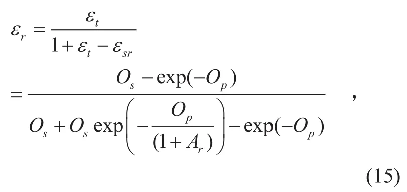
Let’s consider the selection of the optimal relay transmission powerPr.The relay scheme is proposed to compensate the primary performance degradation.Choosing largePrwill improve the outage performance of the primary link but cause higher power cost of the cognitive users.Therefore,Pris selected as low as possible while avoiding primary outage increment,which can be described as:

Obviously,with perfect primary CSI,functionεris a monotonic decreasing function ofPr.Thus,we can recast the optimization problem as following:


we derive the optimal relay transmission power as (18) shown in the bottom at this apge.
4.2 Outage probability with partial primary CSI
If PR employs no combining techniques,the relay precodervRprovides phase shift to allow coherent addition of the signals at PR,and the neutralization precodervNcan still be designed without primary CSI.When the channels are assumed to be reciprocal,the channel gains,which are required to designvN,can be estimated by SUs.However,the relay precodervR,which is needed when PR does not have combining techniques,is quite sensitive to channel phase mismatch of primary link.In this section,we consider that the estimation of primary channel is imperfect at SUs.This scenario is practically meaningful since the channel statements of this link are conveyed to SUs by feedback signals.
Here,the imperfect CSI is modeled through a Gauss-Markov uncertainty of the form [21]:

where parameterηis used to characterize the partial CSI.η=1 corresponds to no CSI knowledge.eppis the estimation error,which is assumed to be complex Gaussian variablesCN(0,1); andis the estimate amplitude of fading channel coefficient of the primary link.AssumingvRis designed ignoring the CSI imperfection,then
Due to the channel uncertainty,the retransmission of PU experience additional outage,whose probability is given by:
Eq.(20) corroborates the intuition that increasing the parameterηleads to decrement of the efficacy.Hence,we defineηathat ref l ects the INR’s ability of tolerating the channel estimation error to make the received SINR equal to the interference-free situation in the retransmission round,which means the assistance provided by the relay is offset by the interference caused by channel uncertainty.Therefore,ηasatisfies the following equationwhereis the interference-free primary transmission SINR.Finally,is a random variable that is dependent on the distribution of the estimation error,it means without combining techniques,the proposed scheme can only provide diversity gains to the primary retransmission when the uncertainty of the primary CSI satisfiesηη<a.
For completely characterizing the performance of the proposed scheme with partial primary CSI,we derive the primary outage probability in the retransmission period with a givenη:

Note that forη=0,the perfect primary CSI is known by the SUs,(21) reduces to (14).Definingwe derive the primary outage probability with partial primary CSI:

It is obvious that,with a fix relay powerPr,the primary outage probability is a monotonic increasing function ofη,which is verified by simulation as shown in Figure 6.However,if the parameterηis equal to 1,which means the estimation CSI is totally error,the relay will no longer provide assistance to the primary retransmission,but impinging interference to it.Hence,different from perfect CSI case,the primary outage probability may not be a monotonic decreasing function ofPrwith certain values ofη.
Defineηbas the bound of the uncertainty parameter,with which INR can achieve the relay assistance objectiveIt is different fromηa,becauseηbmeets the objectiveThenηbsatisfies the following equation (See Appendix):

Consequently,when PR employs no combining techniques,the effect of partial primary CSI is summarized:
1) Whenηη∈[0,b],INR can provide relay assistance to make the primary outage probability equal to the interference-free transmission
2) Whenη∈[ηb,ηa],the primary performance decrement caused by coexistence secondary communication can not be offset by the relay assistance from INR,but INR can still provide assistance to the primary retransmission;
3) Whenη∈[ηa,1],INR can not provide assistance to the primary retransmission,and SUs should stay silence in the primary ARQ round.
V.SIMULATION RESULTS
In order to guarantee the terminal users’ QoS with relatively small transmission power,which ensures that the dense deployment of femtocell is available [22],typical femtocells have less than four users in practical environment [1].Here,an explicit two-SU instantiation is used as the testbed to simulate the proposed INR scheme (except for figure 4(b)).In this section,the numerical results of the proposed relay scheme are presented.The following parameters have been used:

Fig.4.The primary outage performance comparison of different schemes.
1) The spatial positional relationship of all the communication nodes is fixed during the simulation.The distances of the aimed communication links are fixed to 10,while the distances between the interference links are fixed to 6.
2) The primary transmission power is fixed to beand its rate isRp=0.8 bits per channel use (bpcu).
Figure 4(a) is generated by Monte Carlo simulation technique which averages over 105channel realizations and it illustrates the relationship between the secondary transmission powerPs/N0and the primary outage probability with perfect CSI in different scenarios(no relay; the proposed relay scheme withthe interference-free scenario).This figure verifies that the improvement of the primary outage performance is impressive relatively to the traditional underlay CR (No relay).As thePsincreases,the outage probability with the proposed relay scheme does not increase as much as the traditional underlay paradigm.With the optimal relay power,the primary transmission degradation due to the secondary communication can be exactly compensated by the assistance from the SUs’ relaying.Noting that when the secondary transmit power is less than 8dB,the requiredis less than 10dB,and the proposed relay scheme withcan compensate the primary performance degradation that is caused not only by the secondary transmission but also by the fading of primary link.
Figure 4(b) gives the outage probabilities of primary users versus secondary transmission power with different number of secondary users at different scenarios (the interference-free,no relay and the INR with optimal relay power).We can see that the outage probability of PU increases with larger number of secondary users with no relay,while it remains the same with optimal relay power,although they are deployed with different number of SUs.This is because the INR method can perfectly cancel the interference from the SUs,thus the outage probability is the same as the interference-free scenario.
Figure 5 presents the primary outage probability versus the partial parameterηin partial primary CSI case when the SU transmission power is 20dBandPr=10dB,whereεt=0.9577 andεn=0.5234.This numerical experiment is used to verify the accuracy of(20) and (22).The dashed line is the polynomial curve (degree 2) of the numerical data.The solid line is the theoretical curve according to (22).As shown in figure 5,the primary outage probability increases with the rising partial parameter.However,even when the primary CSI is unknown to the SUs (η=1),the primary outage probability is less than the ones in the no relay case (εt) due to the suspension of secondary transmission during the primary retransmission period.The interference caused by relay could be considered as a coexisting secondary pair.However,in the no relay case,two secondary pairs are communicating simultaneously.
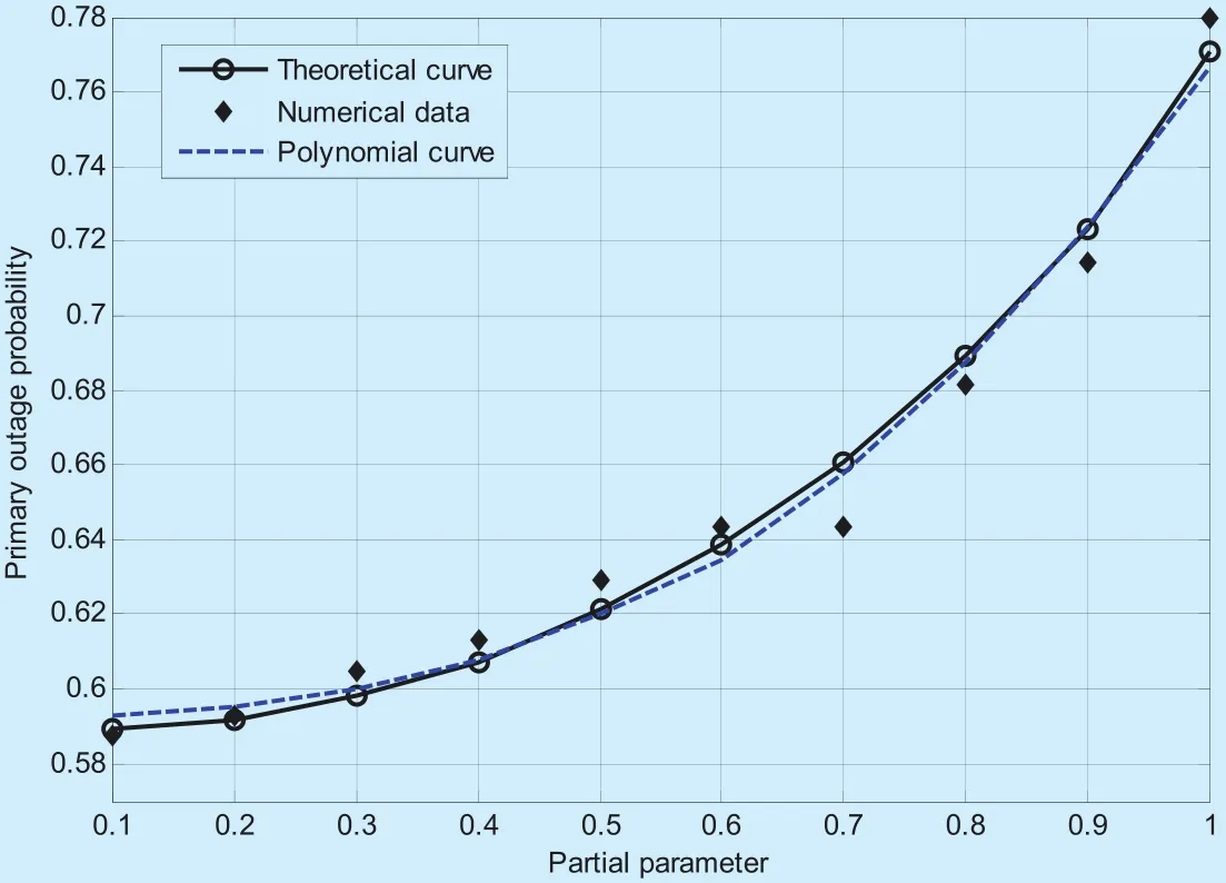
Fig.5.The primary outage performance with partial primary CSI.

Fig.6.The curved surfaces of primary outage performance.
Figure 6(a) shows the outage probabilities of primary user with different parameterηand different secondary transmission powerPs/N0in different scenarios (the interference-free; no relay; the INR with relay power 10dB).At a certainPs/N0,the outage probability increases with the parameterη,which illustrates the intuition that the partial information of CSI will strength the interference caused by the coexisting secondary communication.Apart from that,the surfaces of interference-free scenario and the INR one intersect at a curve,whose points correspond toηbwith a fixed relay power and a secondary transmission power.It’s obvious thatηbdecreases with the increasement ofPs/N0,which illustrates the fact that systems with smaller secondary transmission power can tolerate larger channel estimation error.Besides,the intersecting line of the INR surface and the no-relay one corresponds toηa,and the SUs should keep silence when it’s in the left part of the intersecting line.Corresponding to figure 6(a),figure 6(b)illustrates the effectiveness of INR with different parameterηand different relay powerPrwhen the secondary transmission powerPs/N0is fixed to 10dB.As we can see,whenηis relatively small,that is,ηis close to 0,INR can provide more relay assistance compared to the interference with a proper relay power Pr.Asηincreases,the interference also becomes stronger and a larger relay power is needed.However,ifηis close to 1,INR cannot provide assistance to the primary retransmission any more no matter how large the relay power is.Combining figure 6(a) and figure 6(b),we can get the idea that the INR outstands the no-relay scenario when the estimation error of primary channel is tolerable.
VI.CONCLUSION
This work proposes cooperative relay schemes for the coexistence of primary and secondary pairs of wireless nodes in cognitive femtocell networks under fading conditions.The structure of primary ARQ transmissions is exploited to provide nontrivial relay assistance for the primary retransmission without any prior information of primary data and the initialization phase.The proposed schemes make use of interference neutralization,relaying selection and multi-user diversity.The schemes are analyzed and their performance is numerically verified.The proposed schemes produce attractive results without imposing any overly restrictive assumptions on the system.Simulation results show that,with the optimal relaying power,the decrement of primary transmission efficiency due to the secondary communication can be exactly compensated by the assistance from the proposed relay.They have the further practical advantage of using well-known and well understood system components.
Appendix
As we mentioned in the perfect CSI case,the optimal power problem in the primary partial CSI case can be expressed as:

If optimalPrexists,the feasible region of this problem cannot be empty.In other words,there must have candidate solutions that meets the constraintThus,ηbmust satisfy the inequality:

Defining

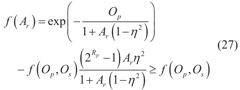
and
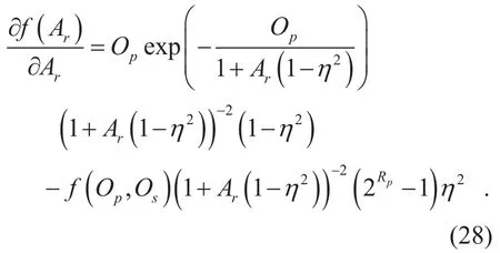
Obviously,Aris a monotonic increasing function ofPr,andf(Op,Os) is independent to the relay power,thus the maximum off(Ar)must be bigger thanf(Op,Os).Ifthe constraint must be satisfied whenPris enough large.Therefore,ηbcan be derived by solving the equationB=0ηb:

ACKNOWLEDGEMENT
This work is partly supported by the National Natural Science Foundation of China(No.61601334,61601509).
- China Communications的其它文章
- Convolutional Neural Networks Based Indoor Wi-fiLocalization with a Novel Kind of CSI Images
- A Study on Service-Oriented Smart Medical Systems Combined with Key Algorithms in the IoT Environment
- Research on Multicloud Access Control Policy Integration Framework
- Towards the Design of Ethics Aware Systems for the Internet of Things
- LLR Processing of Polar Codes in Concatenation Systems
- Initialization for NMF-Based Audio Source Separation Using Priors on Encoding Vectors

