An advanced computational approach for layered structure modeling
PAN Er-nian, ZHOU Jiang-cun,LIN Chih-ping, ZHANG Zhi-qing
(1.Civil Engineering and Disaster Prevention &Water Environment Research Center,Yang Ming Chiao Tung University,Hsinchu 300,China;2.State Key Laboratory of Geodesy and Earth’s Dynamics,Innovation Academy for Precision Measurement Science and Technology,Chinese Academy of Sciences,Wuhan 430077,China;3.College of Architecture and Energy Engineering,Wenzhou University of Technology,Zhejiang 325035,China)
Abstract: In this paper,we present an advanced computational approach for modeling layered structures.The structures can be horizontally layered plates or layered half-spaces.The materials can be multi-field coupled,i.e.,thermoelastic,poroelastic,and magnetoelectroelastic coupled,but require that they are transversely isotropic (TI) with material symmetry axis along the layering direction.This advanced approach is based on the recently constructed Fourier-Bessel series (FBS) system of vector functions and the dual-variable and position (DVP) method.While the DVP is for propagating the layer matrix from one layer to the next with unconditional stability,the FBS vector system is to 1) represent the general deformations/waves with distinguished deformation/wave types,and 2) pre-calculate the expansion coefficients as Love numbers and then use them later for massive simulation of the involved problem.Three typical examples are presented to demonstrate the accuracy and efficiency,as compared with the existing approaches.These are: faulting (or dislocation) in a layered earth,soil-structure interaction,and transient wave propagation in a near-surface earth profile.
Key words: layered media;transverse isotropy;Fourier-Bessel series system;dual-variable and position method;multi-field coupling;Love number
1 Introduction
In nature,many systems present themselves in layered structures:Our global Earth is approximately a spherical and layered body.In its regional scale,we have a horizontally layered half-space.Civil engineers are also often faced with layered half-spaces in their daily research and design.Learned from nature,manmade layered structures are reported from time to time,with excellent physical properties.
When solving the boundary-value problems in the layered structures,the domain-discretization method,boundary-discretization method,and the related hybrid method were proposed[1,2].If the layers are horizontal with material properties in each layer being uniform,analytical solutions can be derived[3].The common approach is to apply either the two-dimensional (2D) Fourier-transform (for general deformation/wave) or Hankel transform (for axis-symmetric geometry,as in Ref.[4-7]) to suppress the horizontal dependences in the governing equations.
Instead of the scalar 2D Fourier transform or one-dimensional (1D) Hankel transform,both Cartesian system and cylindrical system of vector functions can be applied[8-10].The advantages of applying these systems of vector functions are:the dilatational and torsional deformations are clearly decoupled.For wave motion,this means that the P-SV/Rayleigh waves and SH/Love waves are decoupled.Therefore,in terms of these vector functions,not only the governing equations are decoupled but also these decoupled equations are directly physically connected.In other words,once the loading or source type is given,then the corresponding decoupled governing equations can be applied to find the solution.
For the axis-symmetric case,once the solutions are obtained in the Hankel transformed domain,we need to apply the inverse transform to find the corresponding physical-domain solution.This is usually carried out by the numerical quadrature with perhaps the most accurate and fast one being the MATLAB code[11]developed based on the mathematical formulations presented by Lucas and his coauthor[12,13].However,it is still very computationally intensive in most applications.
Another approach is to replace the Hankel integral transform by the Fourier-Bessel series(FBS)expansion[14],as inspired from the spectral element method[15].Compared to the Hankel integral transform,this series approach is computationally more efficient for a given accuracy[16,17].This is due to the fact that,the FBS method requires only simple summation over discrete zero points of the Bessel functions,whilst the inverse Hankel integral transform has to be numerically carried out over each interval between these zero points.Another important advantage which should be particularly emphasized is that the expansion coefficients in terms of the FBS are discrete,and as such,they can be called Love numbers similar to those in the layered spherical Earth[18].Since these Love numbers are discrete,they can be pre-calculated and saved for later use as have been frequently applied in geophysics[19],substantially reducing the computational cost.While the FBS expansion is very efficient and accurate,it was limited to the simple symmetric vertical loading case only.Recently,Pan et al.[20]constructed a complete vector system from the FBS,called FBS system of vector functions.Based on this vector system,any vector as well as scalar function can be expanded so that the very general boundary-value problem in layered structures can be solved.
In the transformed domain,we will have a system of ordinary differential equations (with respect to the thicknesszvariable).This system of equations can be solved in each layer and then various matrix methods can be applied to propagate the solutions from one layer to the next[3].The common ones are the traditional propagation matrix method,also called the Thomson—Haskell method[21,22],the reflection and transmission matrix method[23],the stiffness matrix method[24].Recently,a very powerful method,called the dual-variable and position (DVP) method[25,26]was proposed rooted from the precision integration method[27].We point out that a similar formulation,called compliance-stiffness matrix method,was proposed with applications in electric engineering[28].
In this paper,we briefly review the novel approach we recently developed for handling layered structures:The FBS system of vector functions combined with the DVP method.Its accuracy and efficiency will be illustrated via three typical engineering/science examples:Faulting (or dislocation)in a layered earth,soil-structure interactions,and transient waves in near-surface earth profiles.
2 Boundary-value problem and basic solutions
We use purely elastic materials to illustrate the algorithm.We assume that there is aq-layered transversely isotropic (TI) elastic structure where the last layer could be a rigid base or a homogeneous TI half-space.We place thez=0 plane on the surface of the layered structures with positivezpointing down to the medium.The layers are ordered from top down,with layerlbeing bonded on its upper interface atz=zl-1and its lower interface atz=zl,with a thicknesshl=zl-zl-1.As such,the upper interface of the first layer is at the surface of the layered structure atz=z0=0,and the last interface is atz=zq.The concentrated source can be either a force or a dislocation (fault for earthquake simulation),applied,e.g.,atz=zsin layerj.The special case is the source on the surface withzs=z0=0.Due to the applied force or dislocation,the displacements and tractions (atz=zs) will become discontinuous.Except for this source level,we assume that the displacements and tractions are continuous on all the interfaces.Notice that imperfect interface conditions can be considered if needed[25,26].
In order to solve the problem,the following steps can be applied.
Step 1to get rid of the time-dependence.For the transient (time-harmonic as an example) case,we first apply the Fourier transform to suppress the time-derivative so that only the space-variation is involved.The governing equations are well known,as listed below[25,26]
(1)
σrr=c11εrr+c12εθθ+c13εzz
σθθ=c12εrr+c11εθθ+c13εzz
σzz=c13εrr+c13εθθ+c33εzz
σrθ=2c66εrθ,σθz=2c44εθz,σrz=2c44εrz
(2)
(3)
Step 2to get rid of the horizontal variables in the governing equations (1~3) above.For either axis-symmetric or general 3D deformation/wave (with the angular dependence in terms of different orders of triangular functions),traditionally we apply the Hankel transform of different orders.For instance,following Lin et al.[5]for the general loading case,one can expand the displacements as
(4)
where the involved expansion coefficients on the right-hand sides will be only functions ofrandz(along with frequency-dependence).After that,the Hankel transform is applied to get rid of ther-dependence,by applying
(5)
Instead of Eqs.(4,5),the following cylindrical system of vector functions(CSVF) can be applied[8,9]
L(r,θ;λ,m)=ezS(r,θ;λ,m)
(6)
(7)
whereer,eθ,ezare the unit vectors along the coordinate axesr,θ,z,respectively;Jm(λr) denotes the Bessel function of orderm;andλis the transform variable.Notice that the CSVF is an extension of the scalar Hankel transform to the vector form,and it further processes certain merits to be discussed below.
Since the vector system defined in Eq.(6) is orthonormal,the displacement vectoruand the traction vectort(atz=constant),can be expanded as
UM(z)M(r,θ;λ,m)+UN(z)N(r,θ;λ,m)]λdλ
(8)
t(r,θ,z)≡σrzer+σθzeθ+σzzez=
TM(z)M(r,θ;λ,m)+TN(z)N(r,θ;λ,m)]λdλ
(9)
whereUiandTi(i=L,M,N) are the expansion coefficients of the displacement and traction vectors,respectively;Notice that the body force and any given tractions can be also expanded.This CSVF has been used for many near-surface geophysics,soil-structure interaction,and earthquake engineering problems.The beauty and physics connections are the decomposition of different types of deformations or waves.
The advantages of applying these systems of vector functions are[8-10]:The dilatational and torsional deformations are clearly decoupled.For the wave case,it means that the P-SV/Rayleigh waves and SH/Love waves are decoupled.Therefore,in terms of these vector functions,not only the governing equations are decoupled but also these decoupled equations are directly physically connected.
Very recently,a computationally very efficient vector system,i.e.,the FBS vector functions,was proposed,as defined below[20]
L(r,θ;m,k)=ezS(r,θ;m,k)
(10)
(11)
whereλmkis thekthzero of the Bessel function of orderm,Jm,scaled by a large value ofR,i.e.,Jm(λmkR)=0.Hence,the displacement and traction vectors can be expanded as
u(r,θ,z)=uzez+urer+uθeθ=
UM(λmk,z)M(r,θ;m,k)+UN(λmk,z)N(r,θ;m,k)]
(12)
t(r,θ,z)=σzzez+σzrer+σzθeθ=
TM(λmk,z)M(r,θ;m,k)+TN(λmk,z)N(r,θ;m,k)]
(13)
Then,in terms of the FBS vector functions,the governing equations (1~3)can be reduced to the following linear systems of ordinary differential equations in each material layer,as listed below[20].
For theN-type
(14)
For theLM-type
(15)
We define the following two vectors
U(z)=[UL(z)λmkUM(z)]t
T(z)=[TL(z)/λmkTM(z)]t
(16)
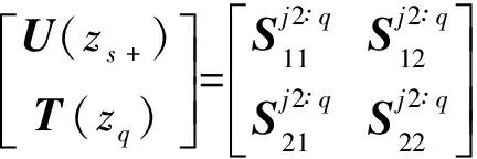
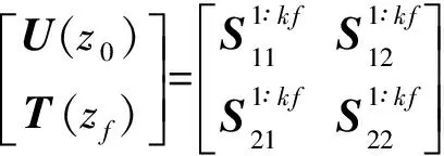
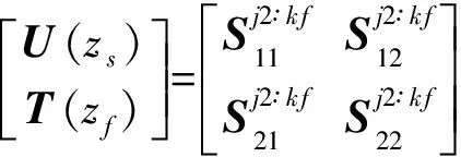
Now,for the given problem with the source in layerj(traction free on the surfacez=z0),we subdivide the source layer into two sublayers asj1 andj2,with their thickness beinghs1=zs-zj-1andhs2=zj-zs.We then propagate from the surface to the upper side of the sourcezs-,and from the lower side of the sourcezs+to the last interface to arrive at Ref.[29,30]

(17)

(18)

(19)
(20)
Thus,for the given discontinuities (or the source functions) at the source levelz=zs,Eqs.(18~20) can be arranged for solving the expansion coefficients.Taking the case where only forces are applied atz=zsand the surface is traction-free (i.e.,Ref.[29,30]),we have,
(21)
(22)
where the scalar functions and submatrices with superscriptq+1 denote the eigenvectors in the last homogeneous half-space[25,26].Notice that here the discontinuity is for the traction only;the corresponding dislocation source can be equally studied,as in Ref.[18].After that,depending on the relative locations of the field points,we can solve for the field quantities at any depth.
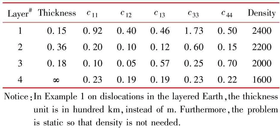
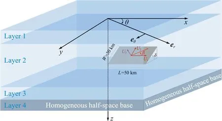
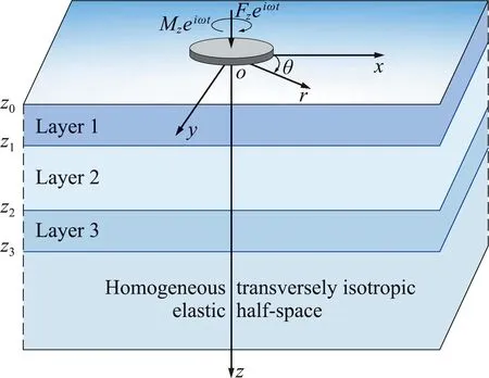
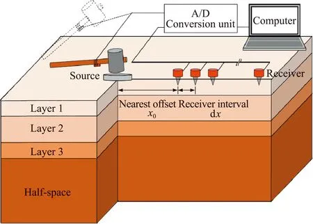
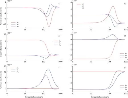
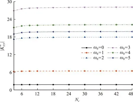
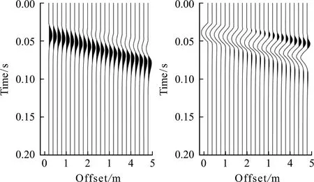
Ifzf (23) (24) (25) (26) Hence the solutions of the expansion coefficients at the field level,along with other quantities,can be expressed as (27) (28) Ifzf>zs:We propagate the layer matrix from the lower side of the sourcezstozfand then fromzftozq,to have (29) (30) (31) (32) The solutions for the unknowns,including other coefficients,can be expressed as, (33) (34) Notice that the traction coefficients on the lower side of the source levelzs+can be expressed by those on the upper side and the given discontinuity source.We also mark that the following more complicated problems can be also solved based on the DVP and FBS system of vector functions:(1)the mixed boundary-value problem in soil-structure interaction[5],(2)the layered structures with imperfect interface[25,26],(3)general dislocations in layered flat Earth[18],(4)poroelastic deformation in layered half-spaces[31],and (5)layered smart structures[32]. For general anisotropy,one could just apply the 2D Fourier integral transform or 2D Fourier series approach.Then,the mathematically elegant and computationally powerful Stroh formalism can be used to derive the first-order differential system of equations[33,34].The Stroh formalism is formed by using both the displacements and tractions expansion coefficients as the unknown functions in each layer,just as we are using the displacement and traction coefficientsUL,UM,UN,andTL,TM,TNhere. For the FBS-based method,we can further apply Kummer transformation to substantially reduce the computational cost.As studied in Ref.[18],for example,for a given accuracy,the direct summation may need more than 100000 terms(or 100000 individual Love numbers);with Kummer transformation where the exact asymptotic solution is utilized,one needs only about 1000 or less terms. To illustrate the advantages of the proposed approach,we carry out three examples with applications.These are faulting (or dislocation) in a layered earth,soil-structure interactions,and transient waves in near-surface earth profiles.In these examples,we assume the following 4-layer TI elastic half-space as listed in Tab.1.However,the source/loading and responses are different,with further the thickness being in hundred kilometers in Example 1,as defined in Fig.1.In Example 2 and Example 3 below for the time-harmonic cases,a small damping factorβ=0.02 is used so that the original elastic stiffnesscijis replaced bycij(1+iβ) where i is the symbol for the imaginary part of a complex variable. Tab.1 Thickness in meter,stiffness cij in GPa, density in kg/m3 In this Example 1,we simulate the co-seismic (i.e.,static) deformation,i.e.3D displacement,on the surface due to a rectangular fault which is located in layer 2 as shown in Fig.1(a).The parameters of the Earth model are listed in Table 1 with the thickness being in hundred kilometers instead of meters.The parameters of the fault are as follows:the left-lower corner is on thez-axis with depth at 50 km,the strike angle is 90° (i.e.alongx-axis),dip angle (denoted byδ) is 50° and rake angle (denoted byβ) is 10°,the length and width are,respectively,50 km and 30 km. It is known that,in a TI medium,an arbitrary fault (dislocation) is a linear combination of four independent ones:vertical strike slip,vertical dip slip,horizontally tensile fracture and vertically tensile fracture[31].Fig.2 shows the Green’s functions (GFs) of these four types (denoted by 12,32,22,33 respectively for the dilatational deformation,and by 12tand 32tfor the toroidal deformation) for the source depth at 50 km.In computing GFs,we setR=5000 km which is sufficiently large.Beyond the circle with radius being 5000 km,the deformation is safely assumed zero.To assure the convergence of the GFs,we sum up about 1000 zeros (i.e.,the series is truncated at about 1000).Notice that since we can pre-calculate the discrete expansion coefficients or the Love numbers,the calculation time is thousands of times faster than the traditional Hankel transform method if 1000 field points are required to draw the curves in Fig.2. (a) A general finite fault in a four-layer Earth with distance in kilometers.The parameters of the fault are as follows:the left-lower corner of the fault is on the z-axis with depth at 50 km,the strike angle is 90° (i.e.,along x-axis),dip angle (denoted by δ) is 50° and rake angle (denoted by β) is 10°,the length and width are,respectively,50 km and 30 km (b) A generally loaded rigid disc on the 4-layer TI elastic half-space (c) Surface waves survey with 24 geophones and earth profile inverse in the 4-layer TI elastic half-space Fig.1 Three typical numerical examples Fig.2 Green’s functions (in meters) of four independent types of dislocation with source depth at 50 km In computing displacements by using the Green’s functions,we need to first approximate the fault by patches.For instance,we use 375 patches where each patch has a size of 2 km×2 km with a uniform slip of 1 m.This means that this fault causes an earthquake with magnitude being about Mw=5.5.Then,we sum up the deformation due to all the patches to obtain the final results.If we use a total of 7200 field points within the 100 km×100 km square to calculate the 3D displacement contours,the present method is then at least 7200 times faster than the traditional numerical integral approach. This Example 2 is to illustrate the application of the proposed method in dynamic soil-structure interaction in the four-layer TI elastic half-space,as shown in Fig.1(b).To understand the soil-structure interaction,one needs the fundamental compliance or stiffness matrix when a generally loaded rigid disc is applied on the surface of or within the layered half-space (e.g.,Ref.[5]).Under the general load as shown in Fig.1(b),the following equation defines the soil-structure interaction stiffness matrix [K][5,30] (37) where the left-hand side is the applied load (forceFiand momentMi) on the disc,and the column matrix on the right-hand side are the displacements (displacementsuiand rotationsθi) below the disc induced by the applied load. The soil-structure interaction is mathematically a complicated mixed boundary-value problem.Taking the vertical loadingFzas an example in whichFzis applied on the rigid disc of radiusr=aon the surface.For this case,the boundary condition on the surfacez=0 of the layered half-space (for frictionless contact and independent of coordinateθ) is (38a) whereuz0in Eq.(38a) is unknown which needs to be determined by the vertical force balance between the appliedFzand the vertical tractionσzzunder the disc,given by (38b) To solve this complicated mixed boundary-value problem,we propose to find the Green’s functions due to the uniform vertical load within the ring area on the surface where the uniform load density is unknown,to be determined by the force balance relation Eq.(38b).Then,an integral least-square approach is applied to finduz0in Eq.(38a)[30].Finally,the relationship Eq.(38b) between the appliedFzand the displacement under the disc can be found,which solves one of the required soil-structure interaction stiffness elements. Fig.3 Convergence of the normalized vertical stiffness with different ring number Nr(M=100000,R/a=650), for different normalized frequencies In this Example 3,surface waves in the four-layer half-space are analyzed.Waveforms on the surface of the layered half-space are particularly useful in the inversion of shear velocity profile[17,35].For instance,in the multichannel analysis of surface waves (MASW)[36],time-domain vertical and horizontal displacements can be recorded and converted to the dispersion curves to compare with the modeling results.Such comparison would help refine or invert the true velocity profiles in the layered half-space.As such,calculations of full waveforms,dispersion curves and the corresponding modal shapes are all important in the forward modeling. Shown in Fig.4 are the vertical and horizontal displacement waveforms on the surface of the four-layer TI elastic half-space induced by a uniform vertical surface load.Here,24 channels on the surface (with nearest offsetx0=0.2 m and spacing dx=0.2 m) are used.The source is applied within a circle of diameter 2a=0.1 m,and in terms of times,as a half-sine pulse with durationTp=0.025 s,expressed as sin(πt/Tp).In the simulation,the parameterR=500 m was used,along with truncation terms atM=10000.When presenting the time-domain surface displacements,we fixed dt=0.0005 s,T=0.25 s (number of time-domain data=500,df=4 Hz,Nyquist frequency=10000 Hz). Since,for a given frequency,the calculation has to be carried out for the 24 channels (or 24 field points) on the surface,the FBS-based method is at least 24 times faster than the Hankel transform-based numerical quadrature.Then,in the time-domain,the computational efficiency would be 24 times the number of frequencies used for inverse Fourier transform.This number is 250 in Example 3.As such,the FBS-based method is more advanced than the existing numerical quadrature methods. Fig..4 Vertical uz(r,t) and horizontal ur(r,t) waveforms obtained from 24 channels induced by a half-sine pulse,where the nearest offset is fixed at x0=0.2 m with fixed space dx=0.2 m,where 250(=500/2) frequencies are used to obtain the time-domain results We have presented an advanced computational approach for modeling layered structures along with three examples of applications:faulting(or dislocation) in a layered earth,soil-structure interactions,and transient waves in near-surface earth profiles.This approach is based on the Fourier-Bessel series (FBS) system of vector functions and the dual-variable and position (DVP) method.While the examples presented are for the purely elastic media showing computational advantages as compared to the existing conventional approaches,this approach can be extended to many other more complicated and coupled material systems,with some of them being under investigation. The first author(E.Pan) has benefitted a lot from Prof.WX Zhong’s precision integration method,and from Prof.G.Lin’s research on soil-structure intera-ction.He would also like to thank Prof.GD Cheng’s invitation to contribute to this special issue.



3 Applications
3.1 A finite fault in a layered half-space
3.2 Vertical disc loading over a layered half-space

3.3 Surface waves in a layered half-space
4 Conclusions
Acknowledgments

