Improving efficiency of inverted perovskite solar cells via ethanolamine-doped PEDOT:PSS as hole transport layer
Zi-Jun Wang(王子君), Jia-Wen Li(李嘉文), Da-Yong Zhang(張大勇),Gen-Jie Yang(楊根杰), and Jun-Sheng Yu(于軍勝)
State Key Laboratory of Electronic Thin Films and Integrated Devices,School of Optoelectronic Science and Engineering,University of Electronic Science and Technology of China(UESTC),Chengdu 610054,China
Keywords: perovskite solar cells,PEDOT:PSS,ethanolamine,doping
1. Introduction
Solar energy can be converted into electricity through solar cells, which is undoubtedly one of the effective ways to solve the current and future energy crisis. The organic–inorganic hybrid perovskite materials can be used to form the active layer of the next-generation solar cells due to their superior optical and electrical properties,such as tunable bandgaps,low exciton binding energy,high absorption coefficients,long diffusion length, and high carrier transport.[1–10]During the past 12 years, perovskite solar cells (PeSCs) have become a research hotspot and a large number of researchers have been involved in the attempt to make them commercialized sooner. It results in a significant improvement in the power conversion efficiency (PCE) for single junction PeSCs, from 3.8% to 25.7% with regular n–i–p planar structure.[11,12]Despite that world record,the devices using the structure usually suffer several shortcomings, such as severe hysteresis effects and poor reproducibility since the thickness of metal oxide electron transport layer (ETL) is difficult to control.[4,13]By contrast, the inverted p–i–n structure can bypass these aforementioned drawbacks. It possesses negligible device hysteresis and can be prepared at low temperature, which means that it has great potential in the fabricating flexible devices.Meanwhile,the record PCE of inverted p–i–n type PeSCs has achieved 24.3%[14]. Therefore, how to improve the performance of inverted PeSC becomes particularly important.
Among the efficient inverted PeSCs, poly(3,4-ethylenedioxythiophene):poly (styrenesulfonate) (PEDOT:PSS) is widely employed as a hole transport layer (HTL) in fabricating PeSCs based on MAPBI3. Because it exhibits high transparency in the visible spectrum region and excellent thermal stability. Meanwhile, it is also suitable for various wet processes such as spraying, spin coating, blade-coating, and 3D printing.[15–18]Nevertheless, the hydrophilic property of PEDOT:PSS will give rise to the rapid crystalization of the perovskite precursor solution with small grain boundary size,which is detrimental to the device performance.[19,20]Besides,the underlying indium tin oxide (ITO) electrode will be continuously eroded due to the acidic nature of PEDOT:PSS.[21]These mean that PEDOT:PSS will damage both the upper electrode and the lower electrode to a certain extent. Furthermore, the shallow work function (?4.9 eV to?5.2 eV) of PEDOT:PSS makes it difficult to match the energy level of perovskite active layer. This will cause the inverted PeSCs base on PEDOT:PSS to suffer severe energy losses, resulting in the poor open-circuit voltage(VOC).[22]If the shortcomings of PEDOT:PSS can be overcome through appropriate modification strategies,its excellent film forming characteristics and low price make it still quite competitive. The common method is to use additives to adjust the physical and chemical properties of PEDOT:PSS films.[23–27]Additive types include the following ones.
(i) Organic small molecules Liuet al.employed PEDOT:PSS with p-type organic small molecule F4-TCNQ doping as HTL to fabricate inverted PeSCs. The PCE of PeSC increased from 13.77%to 17.22%,since the conductivity and energy level of PEDOT:PSS were tuned to match the perovskite active layer.[28]
(ii) Polymer Huanget al.adjusted the optoelectrical property of PEDOT:PSS via polymer PEO doping, which results in the enhancement of PCE for inverted PeSC from 11.13%to 16.75%.[29]
(iii) Inorganic compound A large number of inorganic substances, such as NaCl,[30]CsI,[31]V2O5,[32]and MoOx,[33]were doped into PEDOT:PSS to regulate its physical and chemical properties and improve the crystal quality of the upper perovskite, thus improving the performance of devices.
(iv) Organic solution Different polar organic solvents were used as additives to enhance the conductivity of solution-processable PEDOT:PSS thin films such as dimethylsulfoxide (DMSO),[34]N,N-dimethylformamide (DMF),[35]and glycerol.[36]Besides,appropriate functional groups of organic solution such as–NH2and–OH can passivate the nonradiative defect sites of perovskite,[37,38]which is beneficial to the performance of PeSCs.
Hence, amino alcohols with these two functional groups appeal naturally to us, which has been successfully used as PEDOT:PSS’s additive in the preparation of high-performance perovskite light emitting diodes.[39]
In this work, we present an efficient strategy to improve the performance of inverted PeSCs via doping ethanolamine(ETA) into PEDOT:PSS solution (abbreviated as ETA-doped PEDOT:PSS).The results show that the ETA can improve the electrical properties of PEDOT:PSS including conductivity enhancement and work function adjustment. In addition, it will affect the nucleation and growth of upper perovskites with larger grain size and lower grain trap state. By optimizing the concentration of ETA,the average PCE increase from 12.28%of PeSCs based on pristine PEDOT:PSS to 17.02%of devices on ETA-doped PEDOT:PSS. The champion cell achieved a PCE of 19.16%, with aVOCof 1.06 V and an FF of 80.71%.Besides, owing to the alkaline nature of ETA, it can alleviate the corrosion of PEDOT:PSS to the cathode,so the stability of doped device can be improved significantly. After storing for 2000 h, the PCE can still be maintained at more than 80%of the initial value.
2. Experimental details
2.1. Material
PEDOT:PSS, lead(II) iodide (PbI2) (in purity 99.9%),methylammonium iodide (MAI) (99.9%), [6,6]-phenyl C61butyric acid methyl ester (PC61BM), and 4,7-diphenyl-1, 10-phenanthroline (Bphen) were purchased from Xi’an Polymer Light Technology Corp. ETA(99.5%),ethanol(99.5%),N,Ndimethylformamide(DMF)(99.9%)and chlorobenzene(CB)(99.8%) was purchased from Sigma Aldrich. All materials were used as it was without further purification.
2.2. Film fabrication and characterization
The ETA was first dissolved in ethanol to form a solution with different ratios (0, 25, 50, 75, 100 mg/mL), where 0 mg/mL means pure ethanol solution to determine the effect of ethanol alone. Then,the prepared ETA solutions were mixed with PEDOT:PSS in a volume ratio of 1:9 and stirred for 12 h. MAI(254.4 mg)and PbI2(37.6 mg)were mixed in 1 mL of the DMF solvent and stirred overnight (about 12 h)at 60?C, thereby forming a transparent perovskite precursor.The 20-mg PC61BM and 0.5-mg Bphen were dissolved in 1-mL CB and 1-mL ethanol,respectively. Atomic force microscope (AFM) (Agilent, AFM 5500) was used to characterize the morphologies of the PEDOT:PSS and ETA-PEDOT:PSS.The surface morphologies of perovskite films were investigated by scanning electron microscope (SEM) (ZEISS GeminiSEM 300). The photoluminescence (PL) spectra and transient PL decay properties were measured with an Edinburgh FL1000 spectrometer. Transmission spectra of PEDOT:PSS and Absorption spectra of the perovskite film were measured with Shimadzu 1700. Ultraviolet photoelectron spectra were recorded using the Thermo Scientific Escalab 250Xi with a monochromatized He I (21.22 eV) excitation source. The xray diffraction (XRD) patterns of perovskite films were measured by PANayltical Empyrean powder x-ray diffractometer using monochromatic CuKαradiation.
2.3. Device fabrication and characterization.
The ITO substrates were sequentially cleaned in an ultrasonic bath with detergent, acetone, deionized water, and isopropanol. After drying in an oven, the substrates were treated with UVO for better wettability. Then, differentconcentration ETA doped PEDOT:PSSs were spin-coated on the preprocessed ITO substrates at 5000 rpm for 60 s and annealed at 145?C for 15 min. Then,for all samples,perovskite films were deposited onto the HTL by a one-step spin-coating method as indicated by our previous report.[40]Afterwards,PC61BM solution was spun at 1800 rpm on the perovskite film for 40 s and baked at 110?C for 20 min. Sequentially,Bphen solution was spincoated at 3000 rpm for 30 s. The PeSCs were completed by consecutive vacuum deposition of Ag cathode (100 nm) through using a shadow mask to define the effective device area of 0.02 cm2. Finally,the PeSCs based on the typical structure of ITO/PEDOT:PSS (w or w/o ETA)/MAPbI3/PC61BM/Bphen/Ag were fabricated as shown in Fig. 1(a). The current–voltage (J–V) characteristics were obtained using an Keithley 4200 source/measure unit,and the cell was illuminated by a solar simulator(CHF-XM35,Beijing Trusttech)under AM1.5 irradiation(100 mW/cm2).
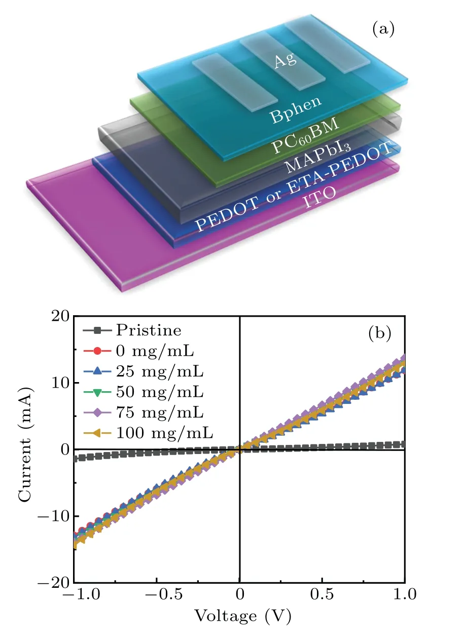
Fig.1. (a)Device structure of PeSCs and(b)current–voltage(I–V)characteristics of ITO/PEDOT:PSS or ETA-doped PEDOT:PSS/Au devices.
3. Results and discussion
Firstly, to assess the electrical conductivity of ETAdoped PEDOT:PSS film, PEDOT:PSS and ETA-doped PEDOT:PSS with concentration are sandwiched between ITO and Au eletrode, where the current–voltage (I–V) characteristics are measured as shown in Fig. 1(b). The conductivity(σ)is derived from theI–Vcurve following[28,41]

whereAandDare the active area and the HTL thickness,respectively.The active area is 0.02 cm2.Both PEDOT:PSS film and the ETA-doped PEDOT:PSS film are measured to be about 40 nm by using the step profiler. The values of conductivity of PEDOT:PSS and ETA-doped PEDOT:PSS with different concentrations are calculated as listed in Table 1. The conductivity of pristine PEDOT:PSS thin film is 2.83×10?5S/m.However,the conductivity of the film is increased by an order of magnitude no matter wheter ETA is added into the ethanol solution during the preparation of PEDOT:PSS films. It can be concluded that the screening effect between counter ions and charge carriers is caused by adding polar organic solvents with higher dielectric constant. The electrostatic interaction between positive PEDOT chain and negative PSS chain will be reduced drastically,thus improving the hopping rate in the PEDOT:PSS film,[42]which leads the ETA-doped PEDOT:PSS conductivity to be enhanced. It is worth noting that when the concentration of ETA increases from 0 to 100 mg/mL,the conductivity of the film also increases slightly,from 2.58×10?4to 2.86×10?4. Therefore, it can be concluded that the doping of ETA can improve the conductivity of PEDOT:PSS HTL,which is beneficial to reducing the overall resistance of PeSC.[43]
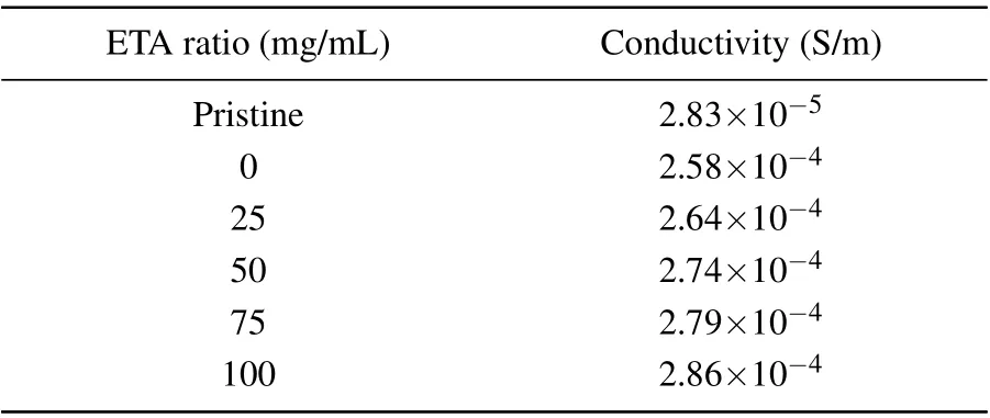
Table 1. Conductivity values for devices with various ETA doping ratios of PEDOT:PSS.
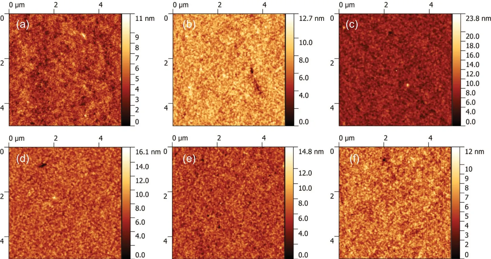
Fig.2. AFM topographies of corresponding perovskite films grown on(a)pristine PEDOT:PSS and ETA-doped PEDOT:PSS with concentration of(b)0 mg,(c)25 mg/mL,(d)50 mg/mL,(e)75 mg/mL,(f)100 mg/mL.
In addition,AFM is used to characterize the surface morphology of the PEDOT:PSS film as shown in Fig. 2. The root-mean-square (RMS) roughness of pure PEDOT:PSS is 0.967, and the RMS roughness values with different ETAconcentrations of 0, 25, 50, 70, and 100 mg/mL are 1.135,1.375, 1.245, 1.162, and 1.127 nm, respectively. It can be seen that the doping concentration of ETA has little influence on the morphology of PEDOT:PSS HTL. All the films show smooth interfaces, which are conductive to the growth of the perovskite active layer. Meanwhile, as shown in Fig. 3(a), it can be found that all the films exhibit good transmittances in the visible light range. However, the transmittance of ETAdoped PEDOT:PSS with 100 mg/mL is obviously lower than them of other films,which will undoubtedly be detrimental to the performance of PeSC.

Fig. 3. (a) Transmittance spectra of PEDOT:PSS with different ETA concentrations, and (b) high-binding energy secondary electron cutoff of the PEDOT:PSS with and without(W/O)ETA doping.
As a crucial link in determining carrier transport,the energy level of PEDOT:PSS and ETA-doped PEDOT:PSS are surveyed by UPS as shown in Fig. 3(b). The work function shifts from?5.1 eV of pristine PEDOT:PSS to?5.35 eV of ETA-doped PEDOT:PSS.It will be more conductive to the extraction of holes from perovskite to anode with the deepened work function after ETA doping, which will generate enough potential barrier at the interface of HTL/perovskite to prevent the carriers from being recombined.
To explore morphologies of the perovskite films prepared on PEDOT:PSS and ETA-doped PEDOT:PSS with different concentrations, SEM images of perovskite films are adopted as shown in Fig. 4. As we can see, the surfaces of all PEDOT:PSS and ETA-doped PEDOT:PSS HTLs are completely covered by perovskite active layers without pinholes.It can be found that the grain sizes of perovskite deposited on ETA-doped PEDOT:PSS with concentration ranging from 0 mg/mL to 100 mg/mL are larger than those on the pristine PEDOT:PSS.Meanwhile,the grain size of perovskite layer increases gradually as the concentration of ETA increases from 0 mg/mL to 75 mg/mL. When the concentration of ETA exceeds 75 mg/mL, the grain size begins to decrease, but it is still larger than that on the pure PEDOT:PSS.
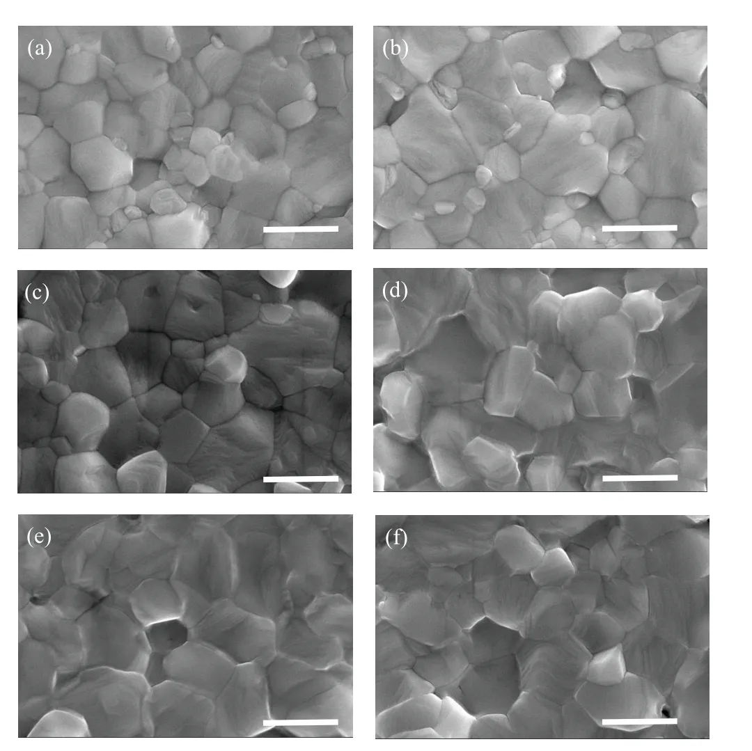
Fig. 4. The SEM images of the corresponding perovskite films grown on(a)pristine PEDOT:PSS and ETA-doped PEDOT:PSS with concentration of(b)0 mg,(c)25 mg/mL,(d)50 mg/mL,(e)75 mg/mL,(f)100 mg/mL,with scale bar being 500 nm.

Fig. 5. Water contact angle of ETA-doped PEDOT:PSS film and PEDOT:PSS film.
To ensure the accuracy, the average grain sizes of perovskite active layers grown on the pure PEDOT:PSS, and on the 0,25,50,75,and 100-mg/mL ETA-doped PEDOT:PSS are calculated to be 370 nm for the former,and 470,500,710,740,and 590 nm for the latter, respectively. The larger grain size results in lower grain boundary density,leading to fewer grain boundary defects in the perovskite films,which is beneficial to device performance. Hence,unless otherwise noted,the ETA mentioned below is the optimal concentration of 75 mg/mL,since the grain size of perovskite film deposited on it is the largest. The increase of grain size is because ETA-doped PEDOT:PSS is more hydrophobic than pure PEDOT:PSS,which can be proved by the water contact angle (WCA) measurements as shown in Fig. 5. As we can see, the WCA of ETAdoped PEDOT:PSS is about 18?, which is higher than that of PEDOT:PSS (~8?). The increased hydrophobic properties of ETA-doped PEDOT:PSS can suppresses the heterogeneous nucleation of upper perovskite layer, contributing to larger grain size and lower grain trap state of perovskite.[44]
The XRD patterns are measured to observe the crystallinity of MAPbI3films grown on PEDOT:PSS or ETAdoped PEDOT:PSS as shown in Fig.6(a). The distinct peaks at 14.16?, 28.24?, and 31.9?, correspond to (110), (220), and(330)faces of the perovskite crystal,respectively.[45]Besides,These three peaks become sharper and stronger for perovskite films on ETA-doped PEDOT:PSS HTL,suggesting the greater perovskite crystallinity. UV-Visible absorption spectra of perovskite active layer deposited on PEDOT:PSS and ETA-doped PEDOT:PSS are also measured as shown in Fig. 6(b). It can be found that the two curves almost overlap,which means that the doping of ETA has little effect on the absorption capacity of the perovskite active layer.

Table 2. Detailed fitting parameters of time-resolved photoluminescence decay curve.

Fig.6. (a)XRD diffraction pattern, (b)absorption spectra, (c)steady-state PL spectra, and(d)time-resolved PL spectra of the perovskite film on PEDOT:PSS without and with ETA doping.
We employ steady-state PL spectra to elucidate the influence of ETA doping on the hole transport and extraction at the HTL/perovskite interfaces. As shown in Fig. 6(c),the perovskite film on PEDOT:PSS and the perovskite film on ETA-doped PEDOT:PSS both exhibit an emission peak at 770 nm under excitation of 465-nm monochromatic light.It can be found that the PL is quenched more severely for the perovskite film prepared on ETA-doped PEDOT:PSS HTL,leading the hole extraction at the perovskite/ETA-doped PEDOT:PSS interfaceto increase.[35]In addition, the timeresolved PL (TRPL) decay curves are measured to study the interfacial charge–carrier–transport process,and the results are shown in Fig. 5(d). The decay time and amplitude of TRPL can be modeled by using a triexponential expression[46,47]

whereIis the normalized PL intensity,A1,A2, andA3represent the fractions of the three decay components, andτ1(fast),τ2(middle),andτ3(slow)are the lifetimes of three decay components. The extracted parameters can be found in Table 2. The average lifetime(τavg)is obtained from the following equation,with theAiandτivalues given by

For the ETA-doped PEDOT:PSS,the value ofτavgis 69.86 ns,which is smaller than 75.45 ns of the pristine PEDOT:PSS,calculated from Eq.(3),which suggests that a faster hole transfers from the perovskite to the ETA-doped PEDOT:PSS.
Based on the above characterization, it can be inferred that ETA doping may improve the performances of the inverted PeSCs. To prove the above inferences, we fabricate the devices based on pristine PEDOT:PSS and ETA-doped PEDOT:PSS with different concentrations. The structure and energy level of PeSCs are drawn in Figs. 1(a) and 7(a). TheJ–Vcurves of PeSCs with different ETA concentrations are shown in Fig. 7(b), respectively, and the extracted photovoltaic parameters are summarized in Table 3. The control device with pristine PEDOT:PSS shows a PCE of 14.67%, at aVOCvalue of 0.986 V, a short-circuit current density (JSC)of 19.90 mA/cm2, and a fill factor (FF) of 74.78%. In order to eliminate the influence of ethanol in ETA solution on device performance, the device with only ethaol,i.e., 0 mg/mL in ETA concentration, is prepared. It is found that the device performance is improved to a certain extent. Comparing with the control device, the PCE is increased by about 5%,reaching 15.49%. With the doping of ETA, the performance of PeSC is improved obviously. When the ETA concentration reaches 75 mg/mL, a peak PCE of 19.16 % is obtained, with the valueJSC,VOC, andFFfixed at 22.35 mA/cm2, 1.062 V,and 80.71%, respectively. The main reason for the improvement ofJSCis the larger grain size of perovskite and the higher conductivity of ETA-doped PEDOT:PSS HTL. The increase ofVOCis mainly due to the reduction of the work function of ETA-doped PEDOT:PSS as shown in Fig.3(b). Further increasing the doping ratio of ETA to higher than 75 mg/mL will degrade performance.As shown in Fig.7(b),the PCE of PeSC with 100-mg/mL ETA concentration yields a PCE of 17.53%with aJSCof 21.97 mA/cm2, aVOCof 1.045 V, and anFFof 76.29%, which may be due to the reduction of perovskite grain size as shown Fig.4.
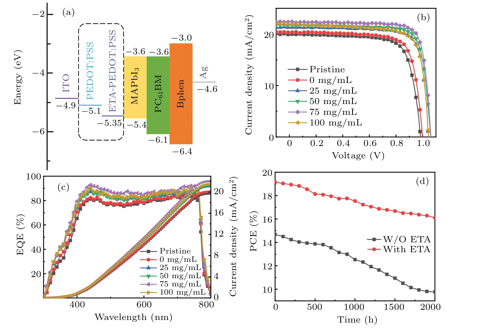
Fig.7. (a)Energy level of each layer for PeSC device,(b)current density–voltage(J–V)curves,(c)EQE profile,and(d)PCE–time curve of PeSC with pristine PEDOT:PSS and ETA-doped PEDOT:PSS HTL.
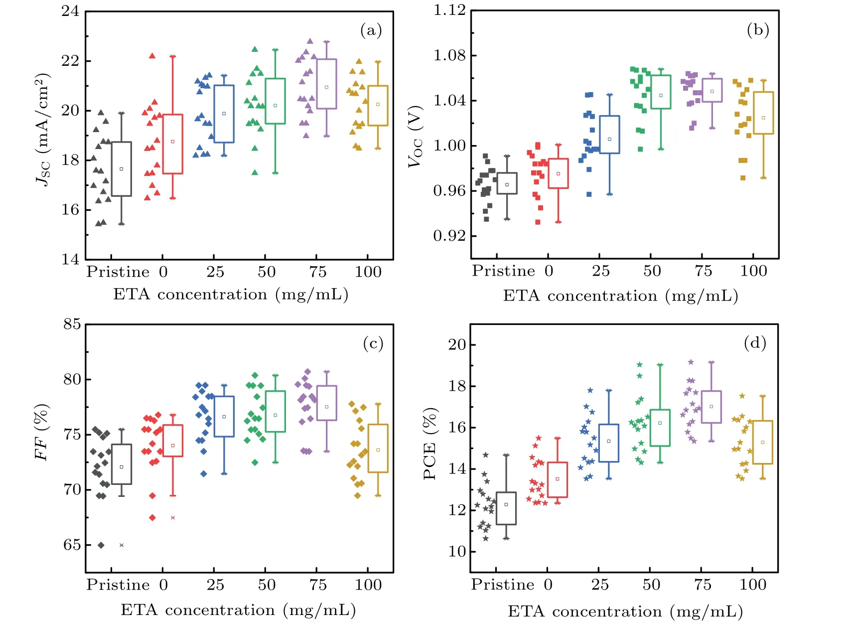
Fig.8.Distributions of JSC,VOC,FF,and PCE of the PeSCs with pristine PEDOT:PSS and ETA-doped PEDOT:PSS HTLs with different concentrations.
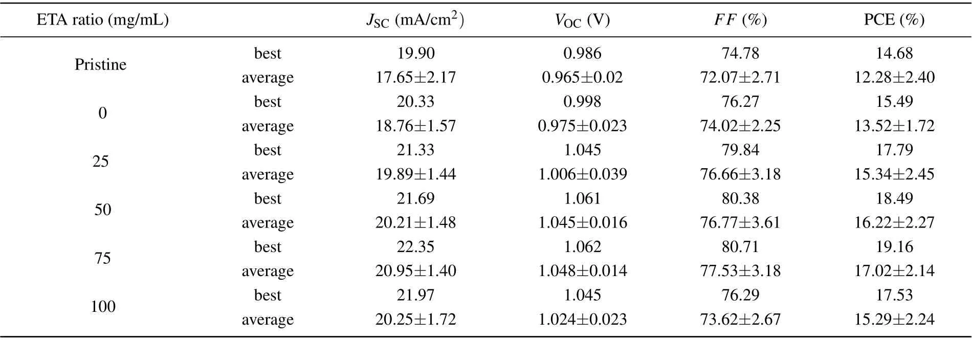
Table 3. Photovoltaic parameters of PeSCs with pristine PEDOT:PSS and ETA-doped PEDOT:PSS HTLs averaged from respective 16 devices.
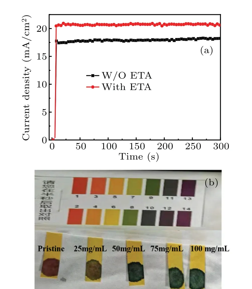
Fig. 9. (a) Current density output of device employing PEDOT:PSS and ETA-doped PEDOT:PSS at MPP,and(b)comparison of pH value between PEDOT:PSS and ETA-doped PEDOT:PSS solution with different concentrations.
Besides, 16 devices are fabricated and characterized at each concentration to guarantee the repeatability of devices.And the distributions of their performance parameters includingJSC,VOC,FF,and PCE are summarized in Figs.8(a)–8(d)and Table 3. As we can see, the trend ofJSC,VOC,FF, and PCE are similar to those in Fig. 7(c). The average PCE of PeSCs based on pristine PEDOT:PSS is 12.28%. And the average PCEs of devices based on ETA-doped PEDOT:PSS with different concentrations of 0 mg/mL, 25 mg/mL, 50 mg/mL,75 mg/mL, and 100 mg/mL are 13.52%, 15.34%, 16.22%,17.02%, and 15.29%, respectively. These results prove that our work is repeatable.
To better illustrate the stability properties of devices and avoid misjudging the PeSCs performance with short voltage sweeps, both devices are tested under maximum power point(MPP) with AM 1.5G illumination then stay steady for the next 300 s of light exposure under ambient conditions as shown in Fig. 9(a). The MPP of the device with ETA-doped PEDOT:PSS is acquired at 0.93 V with a photocurrent density of 20.71 mA/cm2,which is superior to that of the control device measured at 0.82 V with a photocurrent of 17.92 mA/cm2.
Meanwhile,the external quantum efficiency(EQE)spectra and corresponding integrated current curves of PeSCs are exhibited in Fig.7(c). In a range from 400 nm to 750 nm,the EQE values of the PeSCs based on ETA-doped PEDOT:PSS are higher than those based on pristine PEDOT:PSS, which are consistent with theJ–Vcurves as shown in Fig.7(b),implying that the doped device facilitates the charge extraction and charge-carrier transport. Moreover,the corresponding integrated current density calculated according to the EQE spectra with PEDOT:PSS and ETA-doped PEDOT:PSS are shown in Fig.7(c). The integrated current density of PEDOT:PSS is 19.87 mA/cm2, while the integrated current density of ETAdoped PEDOT:PSS with 0, 25, 50, 75, and 100 mg/mL are 20.24, 21.23, 21.37, 22.21, and 21.67 mA/cm2, respectively.These values accord quite well with the experimental data obtained from theJ–Vcurves in Fig.7(b). The margin of error is±5%.
In addition to the enhancement of efficiency, the ETAdoped PEDOT:PSS HTL also improves the stability of PeSCs.The devices are stored in the glove box after being prepared and then placed in the atmospheric environment for testing every 100 h. The PCE of the PeSC with pure PEDT:PSS and ETA-doped PEDOT:PSS HTL each as a function of storage time in ambient air are shown in Fig.7(d). After 2000 h, the relative efficiency of the device with the pristine PEDOT:PSS decreases to 67.1 % of the initial value, whereas the relative efficiency of the device with ETA doping maintains 84.2%.The results suggest the reducing the acidity by ETA doping can make PEDOT:PSS more widely used for developing the PeSCs as shown in Fig. 9(b). A small amount of solution is dropped on the pH test paper. According to the comparison table,the pH value of PEDOT:PSS solution is between 2 and 3. When the ETA doping concentration is 25 mg/mL,the pH value of ETA-doped PEDOT:PSS solution increases to about 5. As the ETA concentration increases further, the pH value of the solution stabilizes at about 9, which can eliminate the influence of PEDOT:PSS acidity on the ITO electrode. Besides,the perovskite layer is deposited on the ETA-doped PEDOT:PSS with larger grain size and lower surface trap,which can provide effective moisture protection.
4. Conclusions and perspectives
In summary, we have demonstrated a simple and robust method to improve the overall performance of inverted PeSCs by employing ETA-doped PEDOT:PSS as HTL. The perovskite film grown onto the ETA doped PEDOT:PSS HTL presents a high-quality crystallization with a large grain size and good film coverage. Besides, owing to the high workfunction PEDOT:PSS with ETA doping, the modified HTL can facilitate the charge separation and improve the charge extraction efficiency, whose PCE is 30% higher than control device based on PEDOT:PSS, thereby leading the PeSC performance to be improved withVOCrising up to 1.06 V and PCE to 19.16%. More importantly, with the acidity reduced,PeSCs based on ETA-doped PEDOT:PSS HTL show excellent long-term stability,which retains over 80%of their initial PCE after being stored in glove box for 2000 h. This strategy can make up for the shortcoming of PEDOT:PSS in the inverted PeSC application and pave the way for the commercialization of perovskite optoelectronic devices.
Acknowledgements
Project supported by the Regional Joint Fund of the Foundation of the National Natural Science Foundation of China (Grant No. U21A20492), the National Natural Science Foundation of China (Grant Nos. 61421002, 61675041,and 51703019), the Sichuan Provincial Science and Technology Program, China (Grant Nos. 2021107, 2019YFG0121,2019YJ0178, 2020YFG0279, 2020YFG0281, and 2021107),and the Fund from the Sichuan Province Key Laboratory of Display Science and Technology,China.
- Chinese Physics B的其它文章
- Magnetic properties of oxides and silicon single crystals
- Non-universal Fermi polaron in quasi two-dimensional quantum gases
- Purification in entanglement distribution with deep quantum neural network
- New insight into the mechanism of DNA polymerase I revealed by single-molecule FRET studies of Klenow fragment
- A 4×4 metal-semiconductor-metal rectangular deep-ultraviolet detector array of Ga2O3 photoconductor with high photo response
- Wake-up effect in Hf0.4Zr0.6O2 ferroelectric thin-film capacitors under a cycling electric field

