Application study on plasma ignition in aeroengine strut–cavity–injector integrated afterburner
Li FEI (費(fèi)力), Bingbing ZHAO (趙兵兵),?, Xiong LIU (劉雄),Liming HE (何立明), Jun DENG (鄧俊), Jianping LEI (雷健平),Zichen ZHAO (趙子晨) and Zhiyu ZHAO (趙志宇)
1 Air Force Engineering University, Xi’an 710038, People’s Republic of China
2 Aviation University of Air Force, Changchun 130022, People’s Republic of China
Abstract To increase the thrust-weight ratio in next-generation military aeroengines, a new integrated afterburner was designed in this study.The integrated structure of a combined strut–cavity–injector was applied to the afterburner.To improve ignition characteristics in the afterburner,a new method using a plasma jet igniter was developed and optimized for application in the integrated afterburner.The effects of traditional spark igniters and plasma jet igniters on ignition processes and ignition characteristics of afterburners were studied and compared with the proposed design.The experimental results show that the strut–cavity–injector combination can achieve stable combustion,and plasma ignition can improve ignition characteristics.Compared with conventional spark ignition,plasma ignition reduced the ignition delay time by 67 ms.Additionally,the ignition delay time was reduced by increasing the inlet velocity and reducing the excess air coefficient.This investigation provides an effective and feasible method to apply plasma ignition in aeroengine afterburners and has potential engineering applications.
Keywords: integrated afterburner, aeroengine, plasma ignition, ignition process, ignition characteristics
1.Introduction
With the advancement of military aircraft performance requirements, a high thrust-weight ratio is a key component of aeroengine development[1].As an integral part of aeroengines,the afterburner plays a significant role in improving the thrust of the engine.The afterburner can effectively improve maneuverability and widen the flight envelope of military aircraft.Conventional afterburner structures are generally composed of fuel injectors,flame holders,and the augmentor liner,as shown in figure 1 [2].
However, many problems [3–5] have arisen with conventional afterburners.The structures of the afterburner components are often complex,which increases the weight of the engine and the flow loss of the engine’s main flow.One solution is an integrated structure design[6–8].Concurrently,the development of aeroengine technology and the improvement of aircraft maneuvering performance have led to the flight envelopes of aircraft becoming increasingly wider.The afterburner encounters ignition challenges and has a narrower ignition boundary when the aircraft flies at a low indicated airspeed and high altitude.Commonly used afterburner ignition methods include prechamber ignition [9], hot jet ignition [10] and catalytic ignition[11].However, these traditional ignition methods cannot simultaneously optimize the various factors of structure,weight,reliability,and cost,which limits the ignition performance of the afterburner.Thus,it is essential to explore new ignition methods for improving afterburner ignition performance.
To solve the aforementioned optimization issues, various integrated structures that combine the functions of multiple components in the afterburner have been developed [12–14].At Michigan State University, Driscollet al[15] studied the effects of cavity size and fuel injection location on the blowout limit of the combustion flame,investigating the basic law of flame combustion.Miaoet al[16–18] performed flow field and ignition experiments of afterburners with different cavity–strut structures and analyzed the influence of different strut angles on flame propagation and flame stabilization.These studies mainly combined several components into the afterburner and simplified the structure of the afterburner to some extent.Further development of integrated design is necessary to reduce the mass of the afterburner and improve the combustion performance.Hence, following the concept of integrated structures, the components of the afterburner were further simplified in this study.
Researchers have performed significant studies on the structure scheme and flame stabilization of afterburners[19–21].However, less attention has been paid to new ignition technology of afterburners.In recent years, plasma ignition has been singled out due to its many attractive advantages [22–25].Because the generation of plasma is accompanied by heat, active particles, ionic wind, Coulomb force, and Lorentz force, the mechanism of plasma ignition can be characterized by high-temperature, chemical, and jet flame effects [26–29].Plasma generation can improve ignition capacity, widen the ignition boundary, reduce ignition delay time,and achieve reliable ignition at low pressure,lowtemperature, and lean fuel conditions [30–32].
In this study, a strut–cavity–injector integrated afterburner and a plasma jet igniter were designed.As a new type of ignition technology, plasma ignition was applied to an integrated afterburner for the first time.Experiments were carried out to compare the effects of a plasma jet igniter and a spark igniter on the ignition process and the ignition characteristics of an integrated afterburner.The results provide a basis for the application of plasma ignition in an integrated afterburner.
2.Experimental system and devices
2.1.Experimental system
The experiments in this study were conducted on a grounddirected test rig.The experimental system was comprised of an air supply system, fuel supply system, aeroengine combustor, afterburner, igniter, and measurement system.The total length of the experimental model was 1500 mm.The detailed experimental system is shown in figure 2.
A fan-shaped test section in the combustion chamber was used to stimulate the high-temperature and low-oxygen gas mixture.Aviation kerosene and oxygen were burned in the combustor, producing a high-enthalpy inflow.The temperature of the vitiated inlet air was measured using B-type thermocouples.A flue gas analyzer was used to measure the oxygen content of the afterburner inlet airflow.The expansion ratio of the expansion section was 1.5.The flame was recorded using a charge coupled device (CCD) camera(FASTCAM Mini WX100) through the observation window which was installed on both sides of the integrated afterburner and fitted with a 50 mm focal-length lens.The ignition process was tested under the operating conditions listed in table 1.
2.2.Strut–cavity–injector integrated afterburner
Combining the research of afterburners and the developmental trend of integrated afterburners, the structure of the strut–cavity–injector integrated afterburner designed in this study is shown in figure 3.In these experiments, the strut performs three roles: part support, fuel injection, and flame stabilization.The thickness of the strut is 40 mm with a back angle of inclination of 70° [33, 34].The flame-holding is accomplished by the cavity in conjunction with the strut,which is vertically located upstream of the cavity.Fuel is ignited by a high-enthalpy plasma jet produced from a plasma jet igniter mounted at the trailing edge of the cavity.
2.3.Plasma jet igniter
The plasma jet igniter designed in this study is composed of a positive pole,negative pole,swirler,electrode mount,isolated base, and stainless-steel casing, as shown in figure 4.Both positive pole and negative poles are made of tungsten–copper alloy (tungsten 70%; copper 30%) with good electrical conductivity and current ablative resistance.The negative pole rod is mounted on the electrode mount and is fixed by a swirler.The minimum distance between the tip of negative pole and the positive pole is 1 mm with a swirl angle of 30°.The power supply used in the plasma jet igniter is a customized DC plasma ignition driving power supply.The breakdown voltage of the driving supply is 10 kV and the output current adjustment range is 20–40 A.After the power supply is connected, a high potential difference is formed between the negative pole and the positive pole of the igniter and an arc is formed by breaking through the air feedstock at the shortest distance.The arc discharge produces a hightemperature, heating the air feedstock.Because the discharge is generated in a very small, confined space, a high-temperature and high-speed plasma jet will be formed at the outlet of the igniter.In the experiment,voltage and current probes were used to collect the plasma igniter discharge waveform.The voltage probe model used was a P6015A with an attenuation coefficient of 1000.The current probe model was a TCP0030 with an attenuation coefficient of 1.The sampling frequency was 10 MHz.
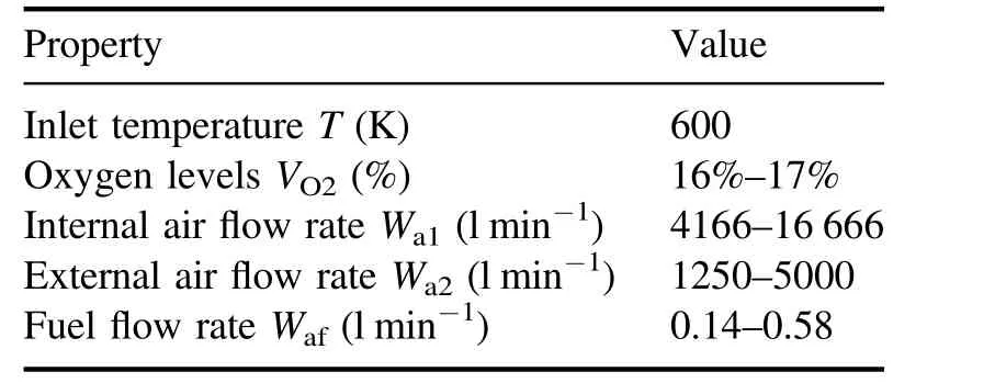
Table 1.Experimental conditions for the integrated afterburner.
2.4.Time sequence
The experimental time sequence is shown in figure 5 [35].The heated air flow begins at the time of 0 s.At the same time, the kerosene is injected into the combustor.A second later, the plasma jet igniter is switched on as soon as a relatively stable flow is established, and the oscilloscope and CCD camera start simultaneously.The flame generates gradually.One second later, at 2 s, the plasma jet igniter is switched off and the combustion is self-sustaining until the end of the experiment.The entire experiment lasts for approximate 5 s.
3.Results and discussion
3.1.Discharge characteristics of the igniter
Figure 6 shows the voltage and current waveforms of the plasma jet igniter discharge process when the plasma power supply output current wasI=25 A and the feedstock flow rate wasWair=45 l min?1.It can be seen from the waveform that the discharge process of the plasma jet igniter is a periodic process[36,37].The discharge process of the plasma jet igniter can be divided into three stages:breakdown process, arc development process, and energy storage process.
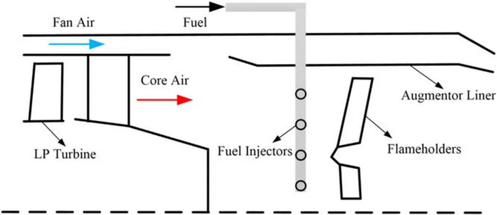
Figure 1.The structure of a conventional afterburner.
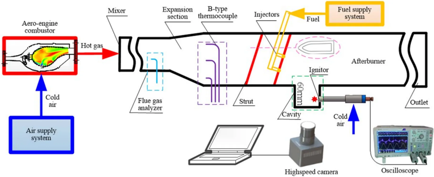
Figure 2.Experimental system of integrated afterburner plasma ignition.
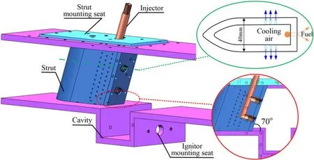
Figure 3.The structure of the strut–cavity–injector integrated afterburner.

Figure 4.The structure of the plasma jet igniter.

Figure 5.Time sequence of the experiment.

Figure 6.Voltage and current waveforms of the plasma jet igniter discharge process.
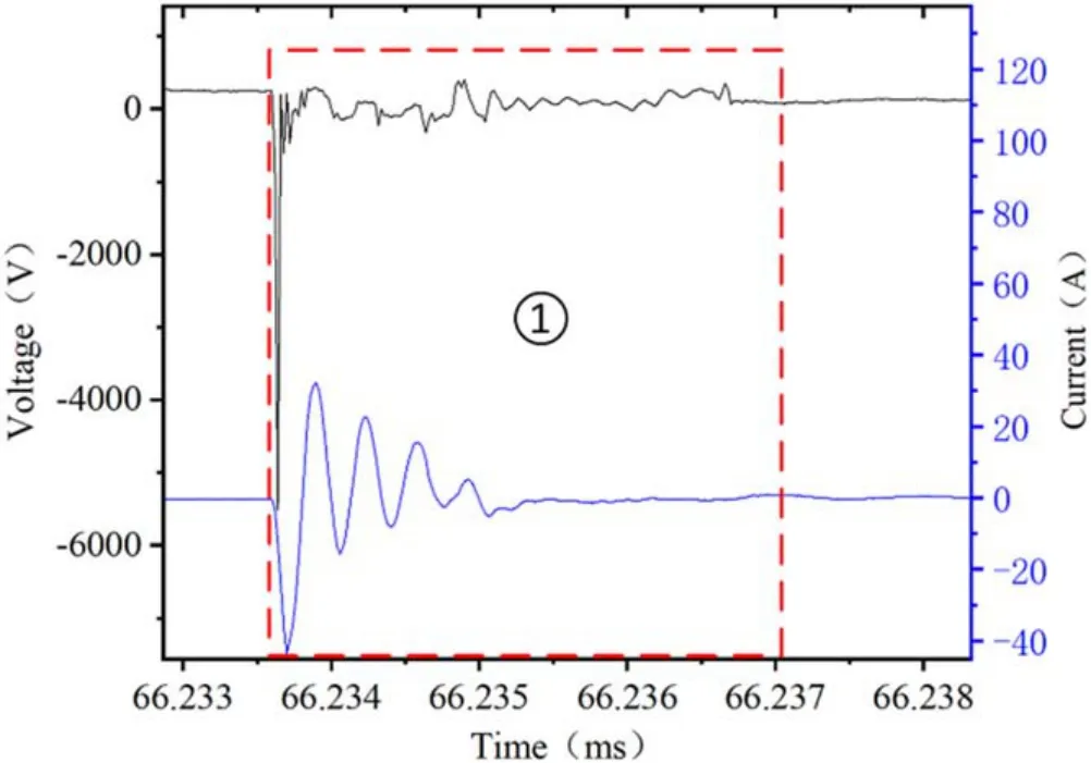
Figure 7.Voltage and current waveforms of breakdown process.
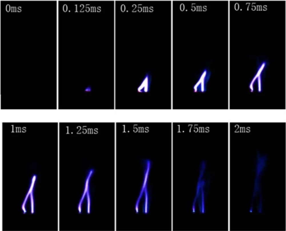
Figure 8.Development diagram of discharge arc motion of the plasma jet igniter.
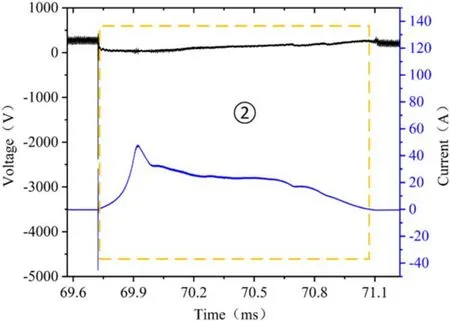
Figure 9.Voltage and current waveforms of arc development process.
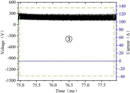
Figure 10.Voltage and current waveforms of energy storage process.
(1) Breakdown process
After the driving power is switched on, the voltage drops abruptly when the breakdown condition is reached.A high potential difference of several kilovolts is formed between the opposing electrodes of the igniter.The narrowest part of the positive pole and negative pole is bridged and an arc is formed.Afterward, the current and voltage begin to attenuate and oscillate to some extent.As can be seen from figure 7, the breakdown process of the plasma igniter discharge occurs rapidly,within a few microseconds
(1) Arc development process.
After the plasma jet igniter successfully bridges to form an arc, it will immediately enter the arc maintenance process.Figure 8 shows the development diagram of the discharge arc motion of the plasma jet igniter captured by the CCD camera.The camera has a shooting speed of 8000 frames per second and a resolution of 1280×296.Under the aerodynamic action of the air feedstock, the arc is constantly stretched.Combining the voltage and current waveforms in figure 9,it can be seen that the longer the arc,the higher the voltage.After the arc motion, the current turns to zero and the voltage falls to oscillate at a non-zero value
(1) Energy storage process.
After the arc is broken and extinguished, the driving power supply of the plasma jet igniter will enter a process of energy storage.In this stage,the voltage is maintained at about 200 V and the current is 0 V, as shown in figure 10.
3.2.Ignition process comparison of a plasma jet igniter and spark igniter
To investigate the influence of the igniter on afterburner characteristics, the comparison of the ignition process of a plasma jet igniter and spark igniter is illustrated in figure 11.The camera has a shooting speed of 2000 frames per second and a resolution of 1280×512.In the experiment, the inlet flow velocity was maintained atV=20 m s?1, the inlet flow temperature wasT=600 K,the output current wasI=30 A, and the excess air coefficient was α=3.In the process of flame establishment, the igniter plays an important role.After the power was switched on, the plasma jet igniter rapidly spouted a high-temperature,high-speed jet, and it was able to continue steadily before the power was switched off.Thus,the fuel was quickly ignited by the plasma jet igniter.However,the spark igniter did not work immediately after it was powered on,and the spark disappeared as soon as it was generated.Within 1 s of the ignition duration,the spark igniter would produce only 3–4 sparks.As a result,fuel was ignited relatively slow.
In order to quantitatively study the plasma ignition process,the ignition delay time was used to characterize the ignition speed.In this study, two photomultiplier tubes were used to measure the spectral signals of O (777 nm) atoms and CH groups(431.4 nm).The ignition delay time of the afterburner is defined as the time interval between the moment when the O atom signal begins to strengthen and the moment when the CH base signal first reaches its peak, as shown in figure 12.According to the experimental results,the ignition delay time of the plasma jet igniter was 22 ms,and the ignition delay time of the spark igniter was 89 ms.Compared with conventional spark ignition, plasma ignition delay time was reduced by 67 ms.
Figure 13 demonstrates the brightness comparison between the plasma jet igniter and spark igniter.As shown in the figure, the plasma jet igniter successfully ignited first.After successful ignition, the intensity of the entire combustion chamber stabilized around a certain value,demonstrating that the combustion chamber can have stable combustion.In contrast, the ignition process of the spark igniter was relatively late, and the flame brightness in the combustion chamber decreased between two sparks.This means that the flame was unstable and could go out, which is unreliable for aeroengines.
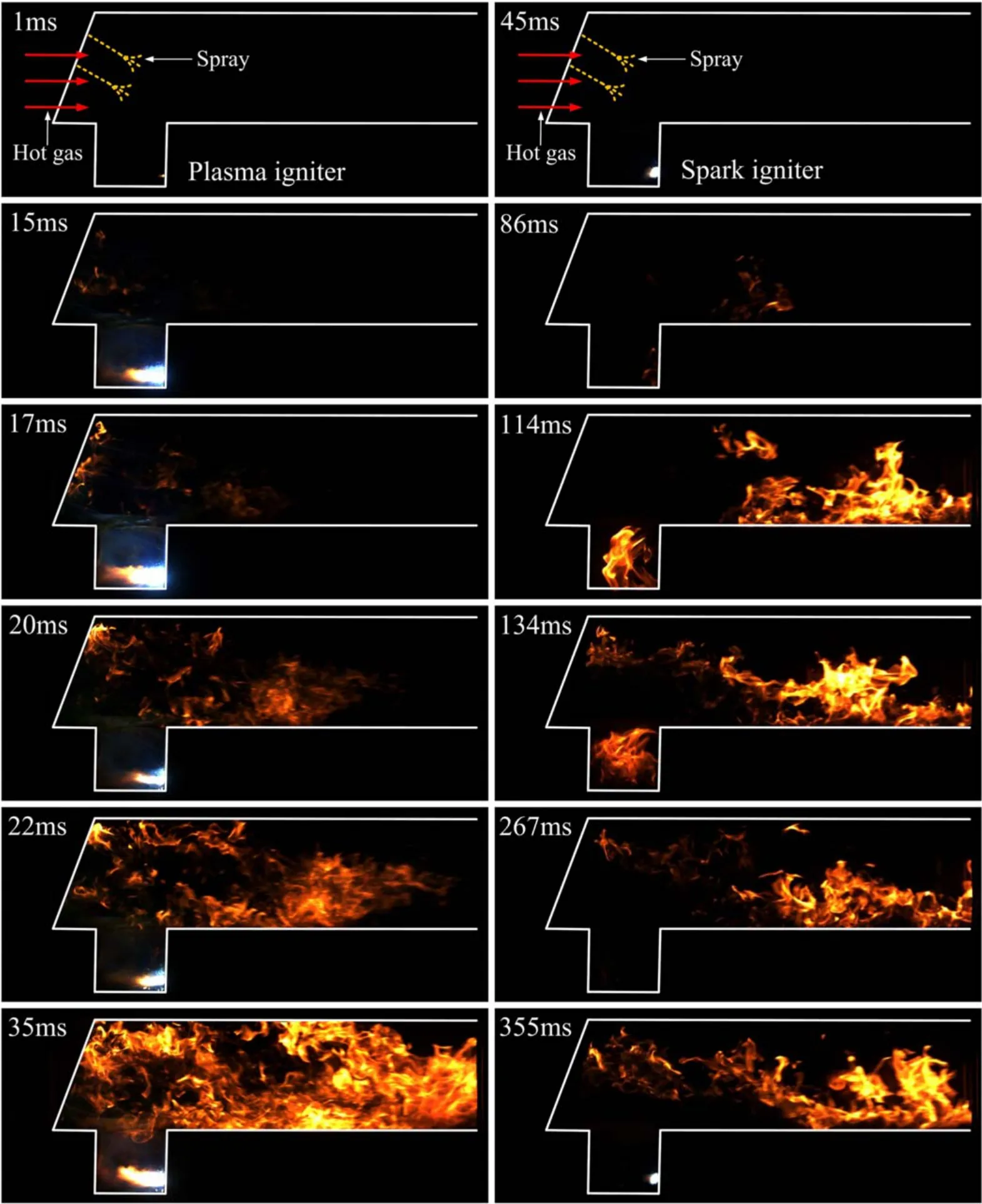
Figure 11.Ignition process comparison between the plasma jet igniter and spark igniter.
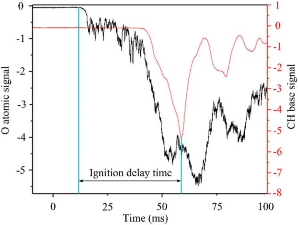
Figure 12.Definition of ignition delay time.

Figure 13.Brightness comparison between the plasma jet igniter and spark igniter.
The plasma igniter discharge produces an extremely high-temperature jet, which can quickly gasify the fuel during ignition.This causes a rapid rise in the temperature of the combustible mixture and speeds up the combustion chain-branching reaction.Additionally, the plasma igniter can eject the plasma jet with greater speed and stronger penetration than the spark igniter can.The plasma jet increases the contact area with the combustible mixture,accelerating the combustion reaction.The igniter discharge area also generates a large number of active particles (such as N atoms, O atoms, H atoms, and OH radicals), which can improve the chemical reaction rate near the discharge area, accelerating the ignition process and reducing the ignition delay time.
Analysis of the experimental results reveals that the plasma jet igniter is superior to the traditional spark igniter in terms of ignition speed and ignition reliability.
3.3.Influence of excess air coefficient (α) on the ignition process
In the experiment, the inlet flow velocity was maintained atV=20 m s?1,the inlet flow temperature wasT=600 K,the output current wasI=30 A, and the flow rate of the air feedstock wasWair=45 l min?1.The CCD camera, oscilloscope, and photomultiplier were used to record the ignition process images and ignition delay time under the conditions of different excess air coefficients (α=1, 2, 3, 5, 7).Excess air coefficient (α) is defined by the equation:

whereWais the mass flow rate of the inlet air,Wfis the mass flow rate of the fuel, andL0is the theoretical combustion air demand for the RP-3 aviation kerosene,L0=14.7 kg/kg [38, 39].
The process of flame kernel generation and flame propagation when the excess air coefficient α=1 and α=3 is shown in figure 14.The camera has a shooting speed of 2000 frames per second and a resolution of 1280×512.The kerosene ejected from the rod first passes through the main recirculation zone behind the strut.Under the action of shear force in the main recirculation zone, the fuel column breaks into small fuel droplets.Some of the fuel droplets vaporize directly under the heating of high-temperature airflow, while some of the unevaporated fuel droplets pass through the main recirculation zone under the action of initial kinetic energy and are sucked into the cavity.The high-temperature jet of the plasma jet igniter ignites the fuel mixture in the cavity quickly and forms a jet flame.
It can be seen from figure 14 that the flame development process under the two excess air coefficients is completely different.First,in the formation and development stage of the flame kernel, the initial flame kernel is directly generated at the head of the plasma jet when α=1 and the initial flame kernel is generated at the root of the plasma jet when α=3.
Second, when α=1, the initial flame kernel does not enter the shear layer along the trailing edge of the cavity to form a shear layer flame.Instead, the flame kernel diffuses directly into the main recirculation zone under the action of plasma jet aerodynamic force and mainstream entrainment effect.However,due to the low flow velocity in the boundary layer of the cavity wall, the initial flame kernel first develops along the trailing edge of the cavity and outward from the cavity when α=3.The flame then rushes out of the cavity and ignites the shear layer.At the same time,the flame in the cavity continues to develop.
Additionally, there are great differences in the formation and stability of the concave cavity pilot flame.When α=1,a vortex flame cannot be formed well in the cavity.The initial flame kernel formed in the cavity cannot be effectively diffused for combustion in the cavity.This is because when the excess air coefficient is small, the fuel supply quantity increases and the fuel outflow kinetic energy increases,which leads to a fuel-rich state inside the cavity.The fuel atomization effect in the cavity is poor and there are even large particles of fuel droplets.The high fuel–gas ratio is not conducive to combustion.Furthermore, there are large areas of shadows in the flame at the head of the recirculation zone.When α=1, excessive kerosene will not fully react in the combustion.Instead,it will evaporate.These shaded areas are low-temperature combustion zones formed by the vaporization of kerosene droplets.When α=3, the flame in the cavity develops better.The gas pressure in the low-speed recirculation zone formed behind the bluff body of the strut is low, which has an entrainment effect on the airflow in the cavity.Additionally,the high-temperature,high-speed plasma jet from the igniter follows the direction of the vortex in the cavity, which strengthens the vortex and enhances the mass and momentum exchange with the mainstream.However, as the excess air coefficient gradually increases and the fuel supply becomes smaller (in addition to the slow ignition process),the self-sustaining flame may not form in the cavity after the plasma jet igniter stops working, causing a failed ignition.
Figure 15 shows the changes of plasma ignition delay time under different afterburner excess air coefficients.The ignition delay time increases with the increase of the afterburner excess air coefficient.Compared with the case where α=1, ignition delay time of α=2 and α=3 is relatively increased by 12 and 37 ms.Also,when the afterburner excess air coefficient continues to increase to a certain range(α=5 and α=7), the main refluent zone in the afterburner cannot form a stable combustion flame.The excess air coefficient has a great influence on the plasma ignition and combustion process of the afterburner.It mainly affects the atomization quality and the distribution of fuel.Too much or too little excess air will cause local lean fuel or rich fuel,respectively,which will have adverse effects on the generation and expansion of a flame kernel, and will seriously affect the propagation of flame and stable combustion.
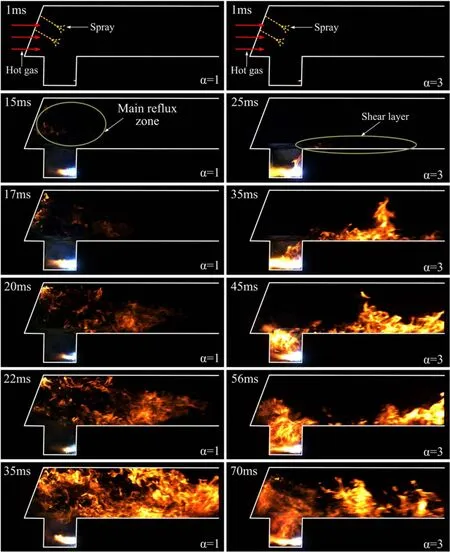
Figure 14.Flame kernel generation and flame propagation process of an integrated afterburner (α=1, 3).
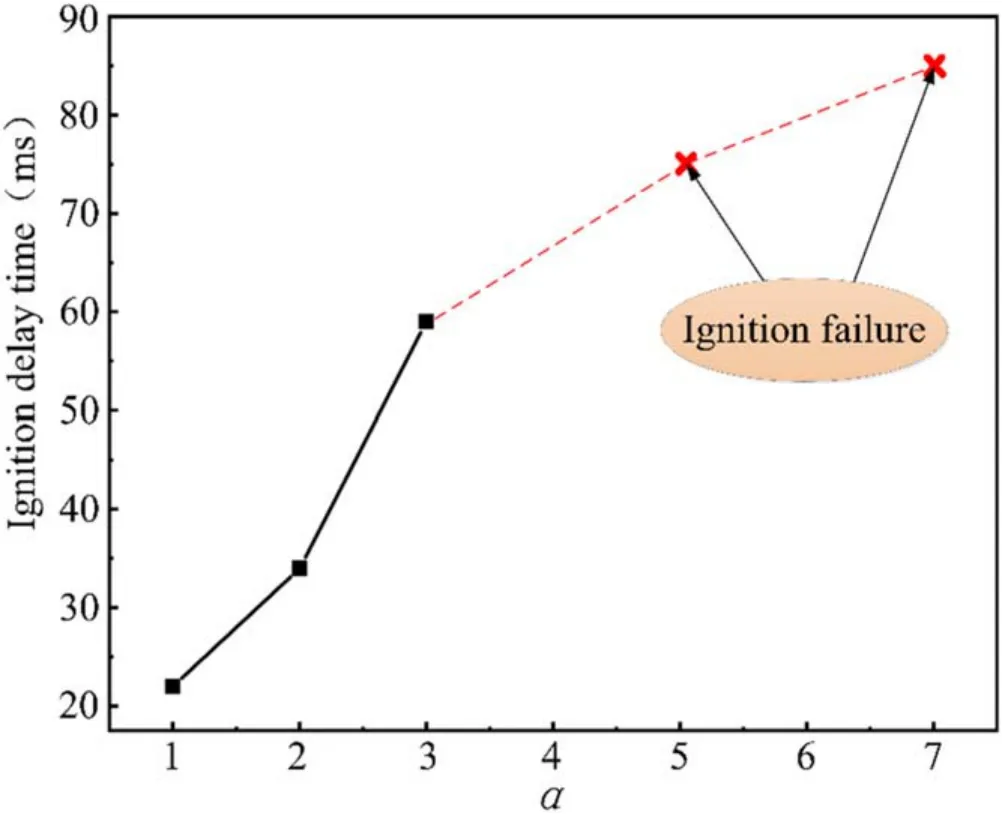
Figure 15.Change of plasma ignition delay time under different afterburner excess air coefficients.
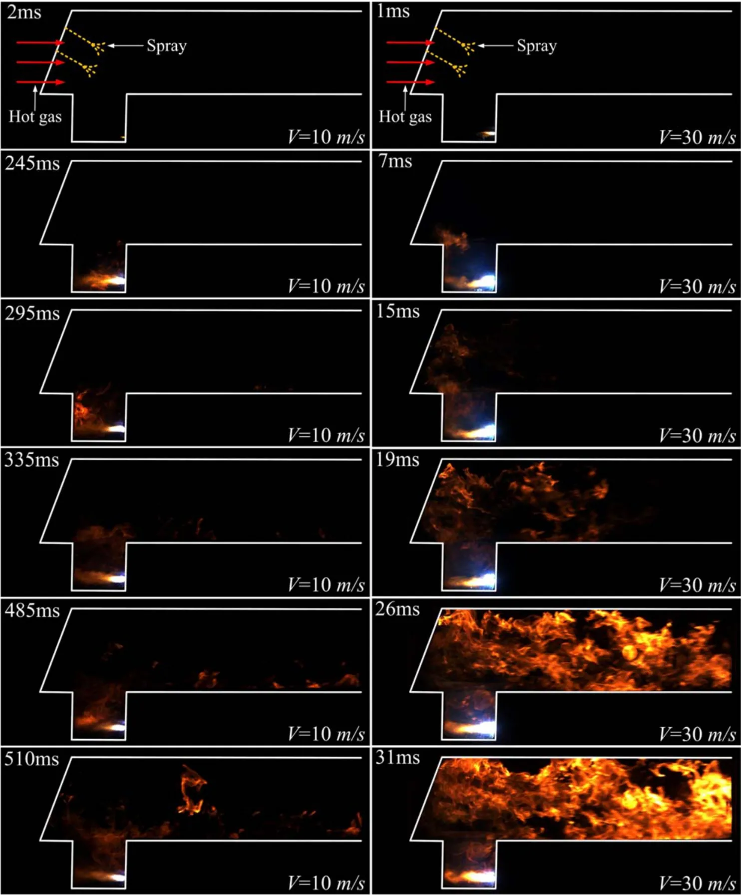
Figure 16.Process of flame kernel generation and flame propagation of an integrated afterburner (V=10 m s?1, 30 m s?1).
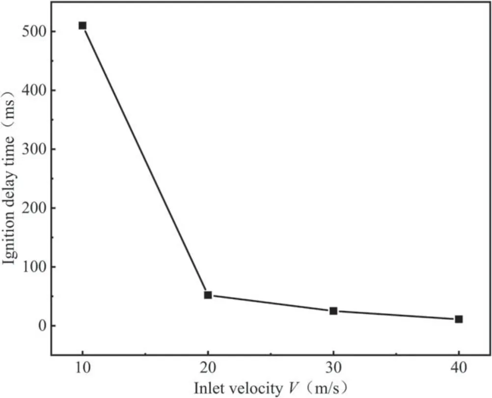
Figure 17.The change of plasma ignition delay time under different inlet flow velocities.
3.4.Influence of inlet velocity (V) on the ignition process
In order to research the effects on the ignition process of changes in the inlet velocity (V), this experiment was conducted with a linearly increasing inlet velocity from 10 to 40 m s?1.In the experiment, the inlet flow temperature wasT=600 K, the output current wasI=30 A, the flow rate of the air feedstock wasWair=45 l min?1, and the excess air coefficient was α=3.The process of flame kernel generation and flame propagation when the inlet flow velocityV=10 and 30 m s?1is shown in figure 16.
As shown in figure 16, when the inlet air velocity of an afterburner is small, the ignition process lasts longer.Att=52 ms,there is still no flame kernel near the plasma jet.Att=245 ms, a jet flame of a certain size is formed and the flame kernel starts to enter the shear layer along the back edge of the concave cavity.The main recirculation zone is not fully lit untilt=510 ms.It can also be seen from figure 16 that the vortex flame and shear layer flame in the cavity are not bright and the flame form in the main recirculation zone is not complete.This indicates that the combustion reaction is not violent under these conditions.
By contrast, the ignition process is significantly shortened when the inlet air velocity isV=30 m s?1.The development process is similar to that when the excess air coefficient is α=1.Both jet flames are formed quickly and directly from the leading edge of the cavity into the main recirculation zone without the formation process of shear layer flame.As shown in figure 16, a jet flame is formed at the end of the plasma jet att=7 ms and the flame expands rapidly.The flame rapidly develops downstream after entering the main recirculation zone.Att=26 ms, the flame reaches the outlet of the afterburner.Then, the flame fills the entire afterburner with stable combustion and bright color.
When the inlet flow velocity decreases, the strength of the recirculation vortex in the main recirculation zone becomes weaker and the strength of the vortex in the cavity also decreases.The decrease of the aerodynamic shear force is not conducive to fuel crushing and atomization evaporation.Also, the convective exchange between the cavity and main recirculation zone is weakened with the decrease of the incoming flow velocity.This is not conducive to flame propagation.Based on the above analysis, the reduction of inlet velocity of the afterburner is not conducive to combustion chamber ignition.The ignition process is more difficult and the flame expansion speed is slower than that in high-inlet velocity.
The change of ignition delay time under different inlet air velocities for the afterburner is shown in figure 17.It can be seen from the figure that the ignition delay time decreases with the increase of inlet velocity, especially at low flow velocity.By comparing and analyzing the ignition process and the ignition delay time under different inlet air velocities,it can be concluded that the influence of inlet air velocity on the ignition process mainly includes two aspects.First,the velocity of inlet air can affect the velocity of flame propagation [40].When the inlet velocity increases, the turbidity of the main recirculation zone and the vortex intensity in the cavity will be increased and the convective exchange effect between the cavity and the main recirculation zone will be enhanced.The flame in the cavity is more easily diffused into the main recirculation zone and the fuel–gas mixture in the main recirculation zone will be ignited more quickly.Second, the velocity of inlet air can indirectly affect the atomization and distribution of fuel.When the inlet air velocity increases, the afterburner fuel supply pressure and amount increase correspondingly.The fuel atomization effect becomes better and the flame kernel formation and flame propagation are easier and faster.Moreover, with the increase of inlet velocity, the enhancement of turbulence intensity of the flow field is also conducive to the crushing and atomization of fuel.This enhances the mixing degree of fuel and airflow, improving the uniformity of fuel distribution and facilitating ignition.
4.Conclusions
In this study, a strut–cavity–injector structure was designed for the afterburner.Experiments on plasma ignition were carried out in an integrated afterburner.The influences of excess air coefficient and inlet velocity on afterburner characteristics were experimentally investigated in terms of the ignition process and ignition delay time.The main conclusions are as follows.
(1) The strut–cavity–injector structure integrates the main functional components of the afterburner, which greatly reduces the size of the afterburner.The experimental results show that the combined structure of the strut–cavity–injector can realize stable combustion.
(2) Compared with conventional spark ignition, when plasma ignition was applied in the cavity,the ignition delay time was reduced by 67 ms.Furthermore, the changing trend of brightness indicated the plasma jet igniter could keep the flame stable after successful ignition.
(3) The ignition delay time increased with the increase of excess air coefficient in the afterburner.Compared with an α=1 operating condition, the ignition delay time under an α=3 operating condition was increased by 37 ms.When the excess air coefficient continued to increase, at α=5 and α=7, the main recirculation zone of the afterburner could not form a stable combustion flame nor a self-sustained cavity pilot flame.
(4) The influence of inlet velocity of an afterburner on the ignition process mainly included two aspects.First,the velocity of the inlet airflow affected the flame propagation speed.Second, the velocity of the inlet airflow indirectly affected the atomization quality and distribution of fuel.The ignition delay time then decreased with the increase of the inlet velocity,especially when the inlet velocity was small.Compared withV=10 m s?1operating condition, the ignition delay time underV=40 m s?1operating condition was reduced by 484 ms.
The experimental results will provide some reference value for the application of plasma ignition technology in the integrated afterburner.
Acknowledgments
This work is supported by National Natural Science Foundation of China (Nos.51806245 and 51436008) and the Science and Technology Projects of Shaanxi Province (No.2020JM-349).
 Plasma Science and Technology2021年10期
- Plasma Science and Technology的其它文章
- Special issue on selected papers from CEPC 2020
- Surface treatment of titanium dioxide nanopowder using rotary electrode dielectric barrier discharge reactor
- Microanalysis of a ductile iron by microchip laser-induced breakdown spectroscopy
- Study on water treatment effect of dispersion discharge plasma based on flowing water film electrode
- Decontamination of infected plant seeds utilizing atmospheric gliding arc discharge plasma treatment
- The regulation of memory effect and its influence on discharge properties of a dielectric barrier discharge driven by bipolar pulse at atmospheric-pressure nitrogen
