Study on water treatment effect of dispersion discharge plasma based on flowing water film electrode
Wenzheng LIU (劉文正), Ying BAO (包穎), Xiaoxia DUAN (段曉霞) and Jian ZHANG (張堅(jiān))
1 School of Electrical Engineering, Beijing Jiaotong University, Beijing 100044, People?s Republic of China
2 School of Science, Beijing Jiaotong University, Beijing 100044, People?s Republic of China
3 Yangtze Normal University, Chongqing 408100, People?s Republic of China
Abstract To improve the utilization rate of plasma active species, in this study, a closed non-uniform air gap is formed by a flowing water film electrode and a sawtooth insulating dielectric layer to realize the diffuse glow discharge in the atmosphere.Firstly, the electric field distribution characteristics of non-uniform air gap in the sawtooth dielectric layer are studied, and the influence of aspect ratio on the characteristics of diffuse discharge plasma is discussed.Subsequently, the effects of wire mesh, the inclination angle of the dielectric plate, and liquid inlet velocity on the flow characteristics of the water film electrode are analyzed.The results show that the non-uniform electric field distribution formed in the sawtooth groove can effectively inhibit the filamentous discharge,and the 1 mm flowing water film is directly used as the electrode,and high-active plasma is formed directly on the lower surface of the water film.In addition,a plasma flowing water treatment device is built to treat the methyl orange solution and observe its decolorization effect.The experimental results show that after 50 min of treatment,the decolorization rate of the methyl orange solution reaches 96%,which provides a new idea for industrial applications of wastewater treatment.
Keywords:water film electrode,dispersive glow discharge plasma,inhomogeneous electric field,closed discharge space, flowing water treatment
1.Introduction
In recent years, the low-temperature plasma generated by atmospheric air glow discharge has been widely studied in air purification, tail gas treatment, and material modification due to its good discharge dispersion,abundant active particles and appropriate power density[1–4].With the deepening research on atmospheric pressure low-temperature plasma, plasma water treatment technology has attracted widespread attention of scholars at home and abroad [5–7].Low-temperature plasma water treatment uses natural air as the excitation carrier through the plasma device,discharges directly in water or water surface to produce plasma and degrades pollutants in water.As a new type of water treatment technology, the plasma degradation process has the advantages of low requirements for temperature and pressure, insensitive to pollutants, and environmental friendliness [8–10].
Plasma advanced oxidation technology has multiple functions such as high energy electron, ozone oxidation,and ultraviolet radiation [11–13].In particular, atmospheric pressure low-temperature plasma will generate plenty of reactive oxygen species and reactive nitrogen species,such as hydrogen peroxide (H2O2), singlet oxygen (1O2), ozone (O3),nitric oxide (NO), and hydroxyl radical (?OH), as well as electrons, ions and photons.These active particles enter into the aqueous solution under the action of multiple physical fields and undergo complex chemical reactions with water molecules, organic solutes, and inorganic solutes [14, 15].The existing plasma water treatment methods mainly include discharge in water, discharge in bubbles by aeration device,jet discharge facing water surface, and diffuse discharge on the water surface [16–19].Shimizuet alused a discharge voltage lower than 10 kV in water to decolorize indigo carmine solution, and the active substances could directly interact with organic pollutants [16].However, the relative rates of transport in the liquid phase will increase the gradients in temperature and concentration between the plasma region and the bulk solution, resulting in recombination and quenching of active radicals in the discharge region.Wang Het alused a synergistic system combining pulsed corona discharge andTiO2photocatalysis to improve the diffusion efficiency of gas-phase substances into the liquid through the gas bubble,thereby increasing the degradation rate of phenol solution [17].However, the aeration equipment in this way complicates the device, which will increase the cost input.Pirdo K Tet alachieved effective decolorization of methylene blue solution by non-thermal plasma jet [18].However,the jet discharge has uneven treatment problems and low effective utilization rate of active particles.Liu W and Li C proposed a water surface contact electrode.The small air gap formed between the electrode and the water surface has strong electric field characteristics, which generates a large and stable glow discharge plasma [19].However, there is a problem that active particles are easy to diffuse into the surrounding air, resulting in a low effective utilization rate and can only deal with surface water.
Therefore,in this work,the liquid surface tension is used to form a flowing film (<1 mm) on the sawtooth insulation dielectric plate.The non-uniform discharge air gap is formed by flowing water film and dielectric plate,which is used as the plasma generation space.In addition, the water film completely covers the dielectric plate, so that a large number of active particles generated by the discharge are directly generated on the water film surface, reducing the possibility of active particles diffusing into the surrounding air.Compared with the traditional plasma method, this method improves single treatment efficiency by using the characteristics of shallow penetration of active particles and provides a new method for plasma water treatment technology.
2.Experimental setup
2.1.Experiment system
The schematic diagram of plasma water treatment device is shown in figure 1.It mainly includes the laboratory-made high-frequency and high-voltage power supply, electrical signal measurement system, and plasma generation device.The output frequency of the power supply is 20 kHz,and the voltage amplitude is 0 to±10 kV.The output terminals of the power supply are connected with the high voltage electrode and the flowing water film electrode, respectively.Tektronix P6015A high voltage probe (1000:1)are used to measure the voltages of the power supply and the resistance respectively,and the difference is the discharge voltage at both ends of the electrode.The discharge current is measured by using a 100 Ω non-inductive resistance.The waveforms of discharge voltageUand currentIare recorded by a Tektronix TDS2014 digital oscilloscope, and the Coolpix P100 SLR camera records the discharge phenomenon of experiments.In addition, the discharge power is measured by replacing the resistanceRwith a capacitance of 0.01 μF to obtain the Lissajous figure.The calculation formula is as follows:

whereTandfrepresent the cycle of the power supply and the working frequency, respectively.The parameterCMrepresents the capacitive voltage.The parameterSrepresents the area of the Lissajous figure.The powerPis proportional toS.
The flowing water film is formed by overflow and flows in a thin film on the sawtooth dielectric plate with mesh.In the experiment, a peristaltic pump is used to realize the circulation between the liquid storage tank and the upper water tank.By controlling the inlet flow rate of the liquid phase and the inclination angle of the dielectric plate, the thickness of the generated liquid film is kept below 1 mm,and the treatment liquid at different times is extracted in the liquid storage tank for detection.
2.2.Electrode structure
The electrode structure is shown in figure 2.The electrodes from top to bottom are flowing water film,polyethylene(PE)wire mesh, polytetrafluoroethylene (PTFE) insulating dielectric plate, and copper plate electrode.The copper plate electrode is a high voltage electrode, and the flowing water film is a grounding electrode.The electrode structure parameters are as follows: the overall length of the electrode is 200 mm, the thickness of the copper plate electrode is 1 mm,and a non-uniform PTFE insulating dielectric plate with a thickness of 1.8 mm (T) is attached to it.Mserrated grooves are arranged side by side to form the non-uniform insulating dielectric plate, and the size parameters of a single serrated groove are length(L)40 mm,width(W)3 mm,and height(H)1.5 mm.Wire mesh is 100 mesh,wire diameter(r)is 0.1 mm,and the aperture (l) is 0.3 mm, which together with the wire mesh and water film form a discharge region.When the appropriate discharge voltage is applied, plasma will be formed in sawtooth grooves.
3.Electric field distribution characteristics and discharge phenomenon
In the study of atmospheric pressure air glow discharge,Ansoft Maxwell 3D electric field simulation software is usually used to analyze the spatial electric field distribution in the electrode structure.
3.1.Electric field distribution characteristics in sawtooth groove
A 4.5 kV voltage is applied to the copper plate on the side of the sawtooth insulating dielectric plate shown in figure 2,and the flowing water film electrode is grounded.The distribution of electric field intensity and characteristics of electric field lines in each sawtooth groove are shown in figure 3.
It can be seen from figure 3 that the electric field intensity in the small air gap between the insulating dielectric plate and the flowing water film is the largest,reaching 1×10⁷V m?1,and gradually weakens from the small air gap to the middle of the sawtooth groove.Besides, the electric field intensity on the surface of the water film is greater than the breakdown field strength of air 3×10⁶V m?1, and the electric field intensity gradually decreases along the vertical direction of the water film.When the electric field lines pass through the insulating dielectric plate and enter the air gap, due to different dielectric constants of the dielectric plate and the air gap, the electric field lines deflect towards the middle of the sawtooth air gap.It is conducive to improving the electric field intensity at point O and making the strong electric field on the lower surface of the water film uniform.
Therefore, under the mutual restriction of electrode voltageUand air gap intervalLg, an uneven electric field distribution with high electric field intensity in the narrow gap and low electric field intensity in the wide gap will be formed in the sawtooth groove.Furthermore, by using this electrode structure,a strong electric field region is formed on the whole lower surface of the water film.According to the discharging principle,it is speculated that the discharge will first appear in the strong electric field area, and then develop to the weak electric field area, and then form diffuse glow plasma.
3.2.The influence of aspect ratio of the sawtooth groove on dispersion discharge characteristics
When the aspect ratio of the sawtooth groove changes, the electric field distribution in the groove will also change.When the applied voltage is 4.5 kV,the depth of the groove is kept constant, and the width of the groove is changed.The electric field intensity of the water film surface(AOC)and the groove surface (ABC) at the aspect ratioK=1,K=2, andK=3 is shown in figure 4.
It can be seen from figure 4(a) that whenK=2, the electric field intensity in the small air gap at the angle between the dielectric plate and the flowing water film reaches 1.3×10⁷V m?1.When the electric field lines enter the water film from the air gap,the wire mesh causes slight fluctuations along the electric field distribution of the water film,but there is little effect on the overall electric field distribution.As theKvalue increases, the air gap at the angle decreases, making the electric field intensity increases.At the same time, the electric field intensity in the middle area of the groove decreases, which makes the middle area unable to reach the breakdown field intensity, resulting in the inability to discharge.It can be seen from figure 4(b) that the amplitude of electric field intensity along the groove surface is too high with the decrease ofKvalue, which increases the possibility of surface discharge.The electric field strength in the middle area of the groove will increase, leading to the rapid development of electron avalanche, thus forming filamentous discharge.Therefore,the aspect ratioKshould be chosen with an appropriate parameter value.
Replacing the water film electrode with wet A4 paper when inclination angle of the insulating dielectric plate is 0°.When the voltages of 3.5 kV and 4.5 kV are applied respectively, the discharge phenomenon in three sawtooth grooves under different aspect ratios is shown in figure 5.
From the discharge phenomenon in figure 5, it can be seen that when the applied voltage is 3.5 kV, the air gaps in the three sawtooth grooves all begin to discharge.As the voltage increases to 4.5 kV, the discharge fills the whole sawtooth grooves.However, when the aspect ratio of sawtooth groovesK=1, the lower surface of the water film presents a bright blue–white discharge area, and there is a filamentous discharge in the groove with a hoarse sound.When the aspect ratio of sawtooth groovesK=2, the lower surface of the water film presents a diffuse blue–violet glow discharge,and the luminous intensity of the groove surface is slightly higher than that of the middle area in the grooves.When the aspect ratio of sawtooth groovesK=3, the discharge at the contact position between the dielectric plate and the water film appears blue–white, while there is an obvious dark area of discharge on the lower surface of the water film.
Since the air gap at the angle between the insulating dielectric plate and the flowing water film is very small, a strong electric field region is preferentially generated at a lower voltage.With the increase of voltage,the strong electric field first discharges, and the electrons in the region diffuse transversely to the adjacent weak electric field region, which participate in the discharge as seed electrons in the weak electric field region.This increases the electron density in the weak electric field area, making it possible to discharge in a larger air gap.WhenK=1, the seed electrons diffuse to the weak electric field region due to the short transmission distance, so that the weak electric field region in the groove is directly broken down due to the excessive seed electron density,resulting in filamentous discharge.WhenK=3,due to the sizeable transverse distance in the groove, the transverse diffusion of seed electrons is weakened, which reduces the electron density in some areas under the water film,resulting in weak discharge.
Therefore,sawtooth grooves can form an uneven electric field distribution with large electric field intensity in the narrow gap and small electric field intensity in the wide gap.It can ensure that the entire lower surface of the water film forms a strong electric field region, and a dispersed glow discharge is formed in the groove.To avoid the occurrence of surface discharge and filament discharge, when the aspect ratioK=2, the discharge effect is better.
4.Flow characteristics of water film electrode
Due to the effect of surface tension and wall adhesion force,the liquid flows through the upper surface of the sawtooth insulating dielectric plate, forming a thin film on the surface of the dielectric plate,and there is a gas space in the sawtooth groove.It provides the possibility for discharge.Because in a relatively short period,short-lived species can quickly convert to other substances due to their short survival time, while long-lived species such as O3,NO?2,NO?3,H2O2in the aqueous solution penetration depth can only reach about 1 mm[20–23].Therefore, in order to improve the efficiency of single water treatment,the target thickness of the water film is set to 1 mm, and Fluent 18.0 simulation software is used to simulate the formation characteristics of the water film.
4.1.Effect of wire mesh on flow characteristics of water film electrode
To increase the contact area between the water film and the discharge air gap and improve the uniformity of the flowing water film,under the premise that the inclination angle of the sawtooth dielectric plate is 45° and the inlet flow rate of the liquid phase is 0.2 m s?1,simulation analysis is carried out on the two structures without mesh and mesh, respectively.Figure 6 shows the water film flow processes under the two structures,i.e.red region represents the liquid phase and blue region represents the gas phase.
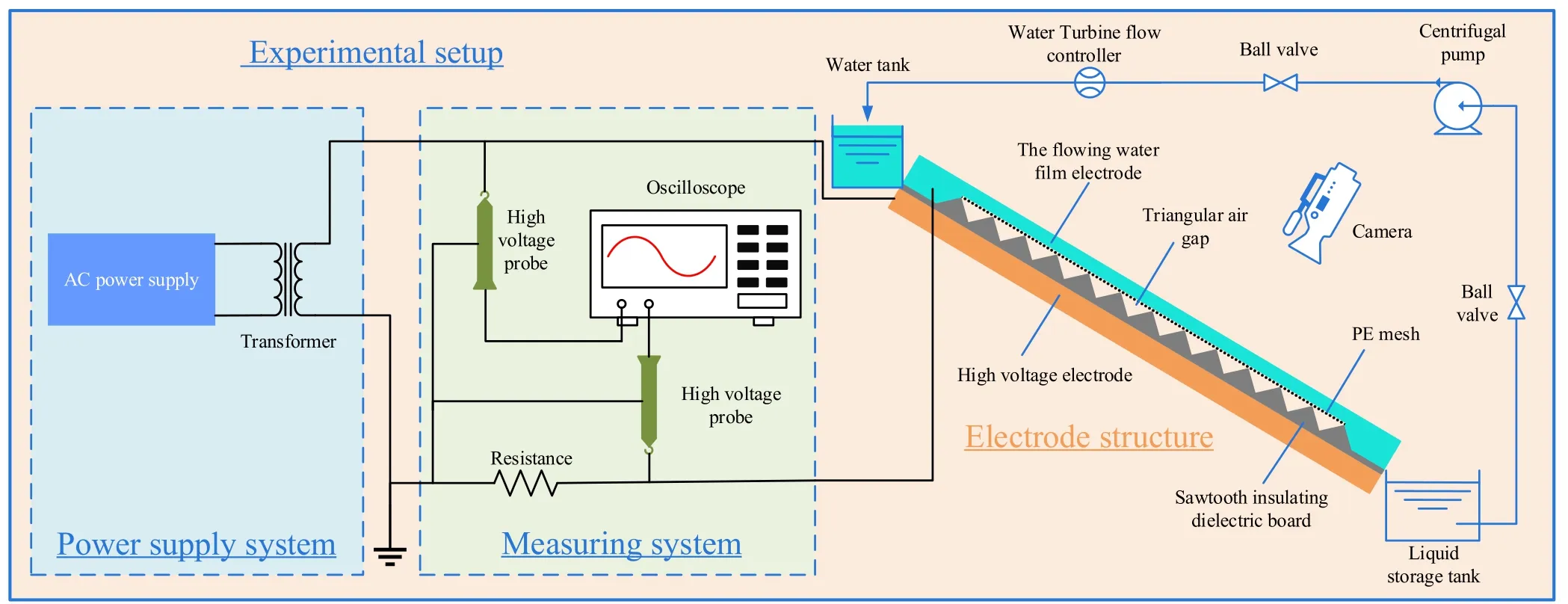
Figure 1.The schematic diagram of experimental device.
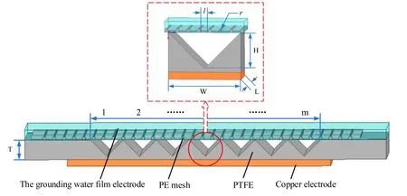
Figure 2.Electrode structure diagram.
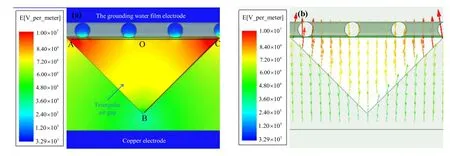
Figure 3.(a) Electric field intensity distribution and (b) electric field line characteristics in each sawtooth groove distribution.
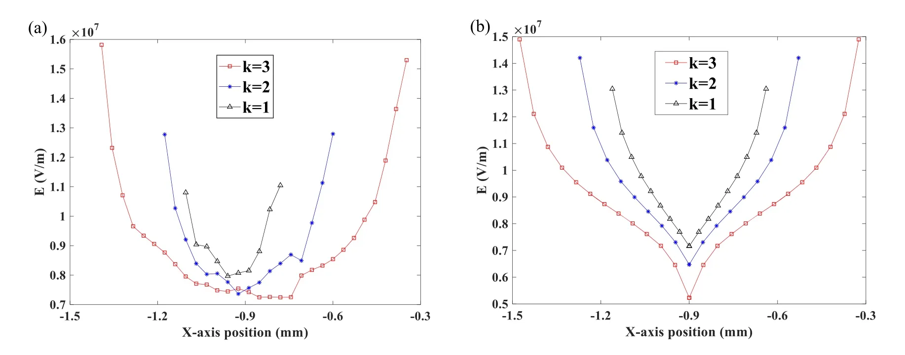
Figure 4.(a) Electric field intensity distribution on the surface of the water film (AOC) and (b) the groove surface (ABC) under different aspect ratios.
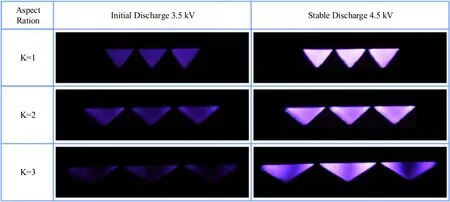
Figure 5.Discharge phenomenon in sawtooth grooves under different aspect ratios (the ISO is 400, the exposure time is 100 μs, and the aperture value is f/2.8).
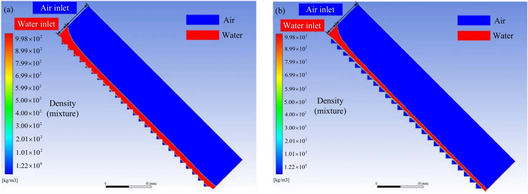
Figure 6.Water film flow process.(a) No mesh, and (b) have mesh.
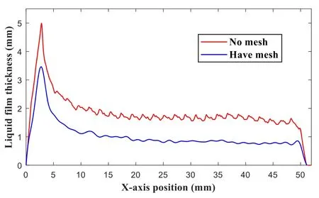
Figure 7.Average water film thickness formed under different structures.
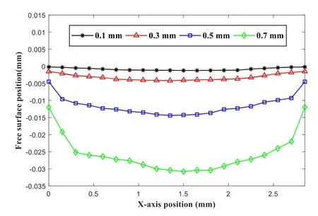
Figure 8.The positions of the liquid surface under the water film with different apertures in a single groove.

Figure 9.Influence of inclination angle of the dielectric plate on water film flow.
It can be seen from figure 6(a)that due to the gravity of the liquid itself, when the water film flows through the no-mesh insulating dielectric plate, the liquid will invade the sawtooth grooves,resulting in a reduction in the discharge air gap,and a few sawtooth grooves are almost filled by the liquid.Moreover,figure 6(b) shows that due to the attraction force between the wire mesh and the surface molecules of the water film(i.e.the wall adhesion force), the surface tension of the water film is stretched, which prevents the infiltration of the liquid effectively under the condition of keeping the aspect ratio of sawtooth grooves unchanged.Therefore, the existence of wire mesh makes the insulating sawtooth grooves have a stable discharge space, ensuring sufficient contact between active particles and the organic matter in the solution.
The average thickness of the water film formed under different structures is shown in figure 7.The average thickness of water film formed by the have-mesh structure is 0.9 mm, while that formed by the no-mesh structure is 1.8 mm.In addition, the lower liquid surface of the water film under the no-mesh structure is greatly affected by the sawtooth grooves, and the fluctuation is severe, which causes the water film thickness to fluctuate significantly.However, the existence of the wire mesh increases the friction force in the water film flow process,which increases the velocity difference between the upper and lower surfaces of the water film, and indirectly improves the uniformity of the flow water film, thus forming a water film with uniform thickness.
Under the same wire diameter,the effect of different mesh apertures on the water flim flow is discussed.When the mesh sizes are 150 mesh, 100 mesh, 80 mesh, and 60 mesh, respectively, and the apertures are 0.1 mm, 0.3 mm, 0.5 mm, and 0.7 mm, the liquid surface position under the water flim is shown in figure 8.
It can be seen from fgiure 8 that when the aperture is greater than or equal to 0.5 mm, the liquid level under the water flim is lower,indicating that the larger the aperture,the easier it is for the liquid to penetrate the sawtooth groove through the mesh.When the aperture is less than 0.3 mm,the water film flow is relatively stable,and the position of the lower liquid level is almost equal to that of the wire mesh,which provides sufficient gas space for the generation of plasma.Therefore, in order to minimize the infiltration of liquid as much as possible and improve the stability of liquid film flow at the same time, 100 mesh PE wire mesh with 0.3 mm aperture is selected in this paper.
4.2.Effect of inclination angle of dielectric plate on flow characteristics of water film electrode
Changing the inclination angle of the dielectric plate is equivalent to changing the action component of gravity in the dielectric plate direction.Due to the viscosity of the fluid, the shear stress can be generated inside the water film under its motion to balance the gravity component along the inclined plane.Figure 9 shows the average water film thickness when the liquid inlet velocity is 0.2 m s?1,and the inclination angles of the dielectric plate are 15°, 30°, 45°, and 60°, respectively.
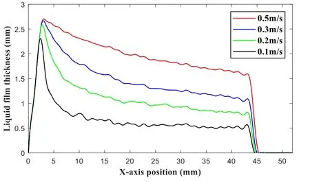
Figure 10.Effect of liquid inlet velocity on water film flow.
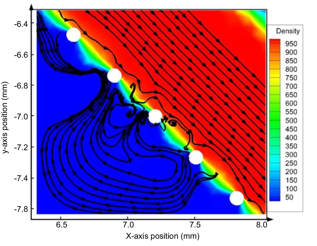
Figure 11.Gas vortex.
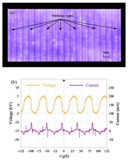
Figure 12.(a) Discharge phenomenon and (b) voltage–current waveform of water film electrode(the ISO is 400,the exposure time is 100 μs, and the aperture value is f/2.8).
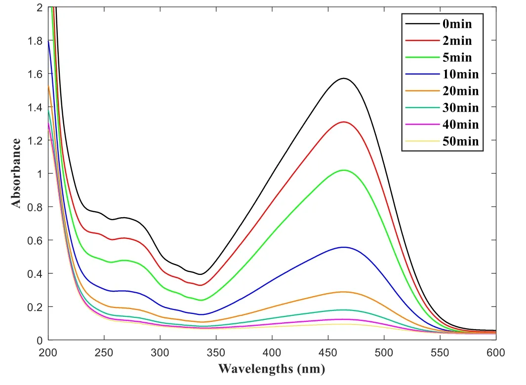
Figure 13.Absorption spectra of methyl orange solution under different treatment time.
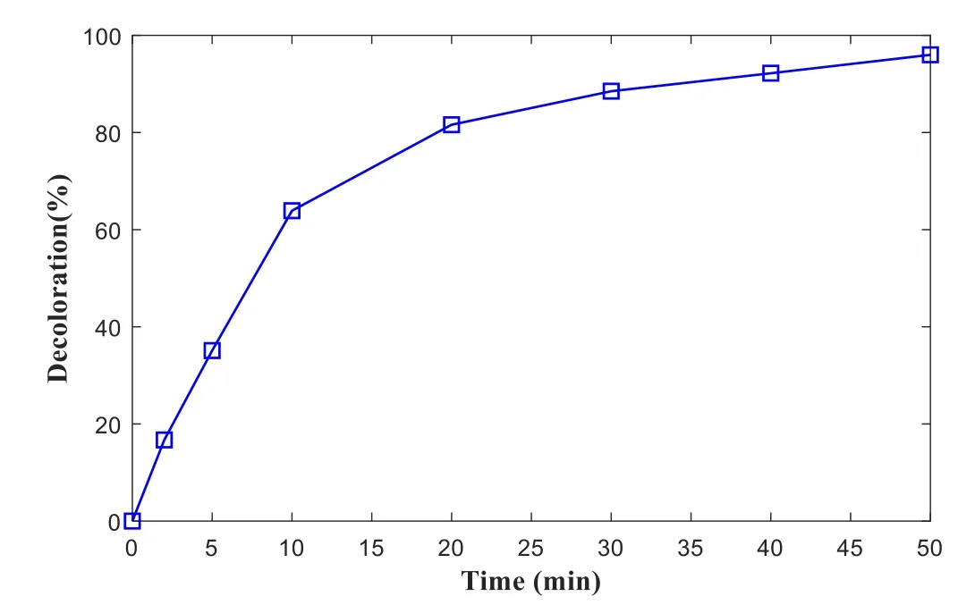
Figure 14.Decolorization rate of methyl orange solution under different treatment time.
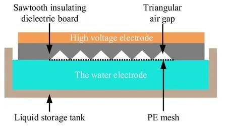
Figure 15.Experimental device for the static water.
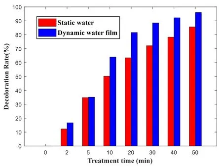
Figure 16.Effect comparison of static water and flowing water film under the same treatment time.
It can be seen from figure 9 that theX-axis is the projection length of the dielectric plate in the horizontal direction.Thus the horizontal projection length of the dielectric plate is different under different inclination angles.Further, when the inclination angle is greater than 30°,a flowing water film with a thickness of less than 1 mm can be formed.As the inclination angle increases,the thickness of the water film decreases,and its motion tends to be stable.Simultaneously,the water gravity component along the dielectric plate direction increases, resulting in the rise of the shear stress inside the film,and the slippage velocity of the upper and lower surfaces of the water film increases,thereby forming a thinner water film.Nevertheless,the inclination angle is too large,making the liquid flow too fast,causing insufficient reaction time between active particles and the organic matter in the liquid film,which reduces the effect of water treatment.If the inclination angle is too small,the shear stress decreases,and the liquid film is affected by gravity, it is easier to penetrate the mesh into sawtooth grooves.Moreover, the smaller the inclination angle, the greater the influence of the wire mesh structure on the liquid film,resulting in flow instability.Therefore,the inclination angle of the insulating dielectric plate is 45°.
4.3.Effect of liquid inlet velocity on flow characteristics of water film electrode
The change of liquid inlet velocity represents the change of entrance flow and Reynolds number(Re).Under the inclination angle of 45°, the average water film thickness formed on the sawtooth dielectric plate at the inlet velocity of 0.1, 0.2, 0.3,and 0.5 m s?1is calculated, as shown in figure 10.
It can be seen from figure 10 that when the flow velocity is as low as 0.2 m s?1,the average water film thickness is less than 1 mm.If it increases to 0.5 m s?1, the water film thickness reaches about 2 mm.That is, the water film thickness increases with the increase of liquid inlet flow velocity.However,if the flow velocity is too fast and the action time of active particles on the organic matter is short, it is necessary to increase the number of water cycles to achieve effective treatment.If the flow rate is too slow,it will increase the time cost and reduce the processing efficiency.Therefore,0.2 m s?1is chosen as the inlet velocity of the liquid phase.
As can be seen from the numerical simulation results,a gas vortex is formed in the sawtooth groove during the flow process,as shown in figure 11.When the water film flows through the serrated dielectric plate,the velocity difference of the gas–liquid contact surface is large,which causes the pressure imbalance in the groove and finally forms the gas vortex.It can be seen from the streamline that the direction of the gas vortex is opposite to that of the water film flow,and terminates at the bottom surface of the water film.It enables the active particles generated far away from the liquid level in the sawtooth groove to be effectively utilized.Also,the existence of a gas vortex accelerates the continuous renewal of the gas–liquid interface, increases the reaction probability of active substances and organic substances,and further improves water treatment efficiency.
5.Discharge characteristics of water film electrode and plasma treatment effect
5.1.Discharge characteristics of water film electrode
Combined with the above simulation parameters, the experimental device shown in figure 1 is built for discharge experiment.The inlet velocity of the flowing water film is 0.2 m s?1, and the inclination angle of the whole plasma treatment device is 45°.When the applied voltage is 3.5 kV, weak discharge occurs in the small air gap at the angle between the sawtooth dielectric plate and the water film.As the voltage increases, the discharge area increases.When the voltage is 4.5 kV, the electrode discharge phenomenon is photographed in the vertical direction of the water film flow,as shown in figure 12(a).It can be seen that the discharge under the flowing water film presents a light blue discharge phenomenon and disperses the whole sawtooth groove.The discharge area is large,and the discharge is uniform and stable.
The voltage and current waveform corresponding to the discharge are shown in figure 12(b).The measurement results show that there is only one main current pulse in the positive and negative half axes of the AC, and it appears in the rising edge of the positive half axis of the voltage and the falling edge of the negative half axis,and the instantaneous value of the maximum pulse current is only 40 mA.According to the calculation formula of the Lissajous figure, on the condition that the discharge voltage is 4.5 kV, the discharge power is 14.4 W.It indicates that the current density is relatively low.That is, no high-density plasma channel is formed in the discharge space.In addition, the pulse current amplitudes of positive and negative half-axis are different, which is due to the other properties of the cathode and the anode surface materials and the asymmetry of electrode shape.In the positive half cycle of the voltage,the copper plate electrode is a high voltage electrode.A large number of low-level traps in the PTFE insulating layer on its side adsorb electrons,and the formed reverse electric field can inhibit the development of electron avalanche [24, 25].On the contrary, in the negative half cycle of the voltage, the water film electrode as a high voltage electrode can absorb electrons, which makes the electron avalanche generated by the insulation electrode side develop smoothly, resulting in that the current amplitude of the negative half cycle is higher than that of the positive half cycle.Combined with the discharge phenomenon in figure 12(a), we judged that the dispersed glow discharge plasma is generated.
Therefore, the water film electrode has unique discharge characteristics.Since the water film has a specific initial conductivity, and the positive and negative ions in the water film can move freely,it can directly participate in the reaction instead of metal as the electrode.In addition,water molecules are typical polar molecules.Under the action of electric field force, hydrogen atoms point to the direction of the electric field, and oxygen atoms deviate from the direction of the electric field,and water molecules move along the direction of the electric field.However, the dielectric barrier discharge(DBD) is used in the AC high-frequency power supply, and the electric field direction changes periodically.When the electric field direction is perpendicular to the liquid surface downward, the flowing water film tends to stretch along the electric field direction.On the contrary,when the electric field direction is upward, the electric field force changes, and the water film deviates from the sawtooth grooves, which causes the water film reciprocate near the wire mesh.Therefore,water molecules and their internal positive and negative ions move under electric field force and collide with particles in the air gap.Moreover, the water film reaches a relatively balanced state under the coupling action of electric field force,surface tension, gravity,and friction force,which will form a relatively stable water film.In this way,the plasma channel is formed in the sawtooth air gap, and free radical active particles with strong oxidation such as·OH,·H,O3are generated on the surface of the water film, which effectively improves the efficiency of water treatment.
5.2.Analysis of plasma treatment effect
5.2.1.Preparation and calculation of methyl orange solution.In this research, the methyl orange solution with a concentration of 20 mg l?1is prepared with deionized water.The initial conductivity is 22.28 μS cm?1, and the pH value of the solution is 6.8.The spectral parameters of methyl orange solution are determined by scanning with a UV spectrophotometer in the range of 200–600 nm.According to Lambert Beer’s law, the concentration and absorbance of the solution have a linear relationship in a lower concentration range.The solution conductivity is determined by a portable conductivity meter (Mettler Toledo Inlab 731-ISM), and the solution pH is measured with a pH meter.The treatment efficiency of the methyl orange solution is characterized by decolorization rate and energy yield.The decolorization rate of the solution is calculated by the formula (2) [26, 27], and the energy yield is calculated by formula (3):

whereA0is the absorbance of the initial solution andAtis the absorbance of the treatment solution.

whereCis the initial concentration of the treatment solution,Vis the volume of the solution,Pis the input power,andtis the treatment time.
5.2.2.The decolorization rate, PH value and conductivity of methyl orange solution.In the experiment, 4.5 kV discharge voltage is applied,and the prepared methyl orange solution is divided into eight groups, and the discharge treatment is carried out for 2, 5, 10, 20, 30, 40, and 50 min respectively.After the discharge of each group is completed,10 ml methyl orange solution is transferred into the colorimetric dish by using a pipette for detection.The UV spectrum of methyl orange solution is shown in figure 13, and the decolorization rate is shown in figure 14.
The test results in figure 13 show that methyl orange has the maximum absorbance at 463 nm.That is, the maximum absorption wavelength of methyl orange is 463 nm.As can be seen from figure 14, with the treatment time increasing, the peak absorption of methyl orange solution gradually decreases, and the decolorization rate increases with the increase of time.This is because many active species in the plasma bombard the C–C bonds and unsaturated bonds in organic molecules, causing a series of organic chemical molecules such as bond breaking and ring opening to decompose the refractory polymer organic matter readily biodegradable small molecules.Moreover, the discharge process is accompanied by physical and chemical reactions such as ultraviolet light radiation and shock waves.These reactions have a synergistic effect with the active particles in the plasma to accelerate the degradation of organic matter[28].In addition, due to the velocity difference between the upper and lower surfaces of the flowing water film, the gas–liquid interface is continuously replaced so that new methyl orange molecules are always exposed to the plasma.As the treatment time increases, the color of the solution becomes shallow,and the concentration of organic molecules decreases gradually.Therefore, the treated solution is treated uniformly and stably throughout the flow process, which effectively improves the treatment efficiency.
In addition, it can be seen from table 1 that with the increase of treatment time,the solution conductivity increased,while the pH value decreased after plasma treatment.It indicates that the methyl orange molecules will be degraded into small molecular organic acids during the plasma discharge process.The active particles generated by discharge will interact with the water film,which makes the water molecules hydrolyze to produce H+.Moreover,when air acts as discharge gas, N2dissociates and combines with excited O to form nitrogen oxides.Nitrogen oxides will react with water to form nitric acid, nitrite, etc, which reduces the pH value of the solution and increases the conductivity of the solution.
5.2.3.Comparison of the effects of flowing water film and static water.The plasma generator is placed horizontally above a static methyl orange solution of the same concentration and volume, as shown in figure 15.Figure 16 shows the effect comparison of static water and flowing water film under the same treatment time.
It can be seen from figure 16 that under the same treatment time, the treatment effect of the flowing water film is better than that of static water.When treating static water,the active particles produced by discharge can only act on the organic molecules on the water surface,and the deep organic molecules need to be treated by diffusion.The flowing water film increases the contact probability of active particles and organic matter, and effectively improves single water treatment efficiency.The experimental results showed thatthe decolorization rate of methyl orange solution reached 92%after 40 min of plasma treatment with flowing water film electrode and 96% after 50 min of treatment.

Table 1.Changes of solution conductivity and pH values at different discharge times.
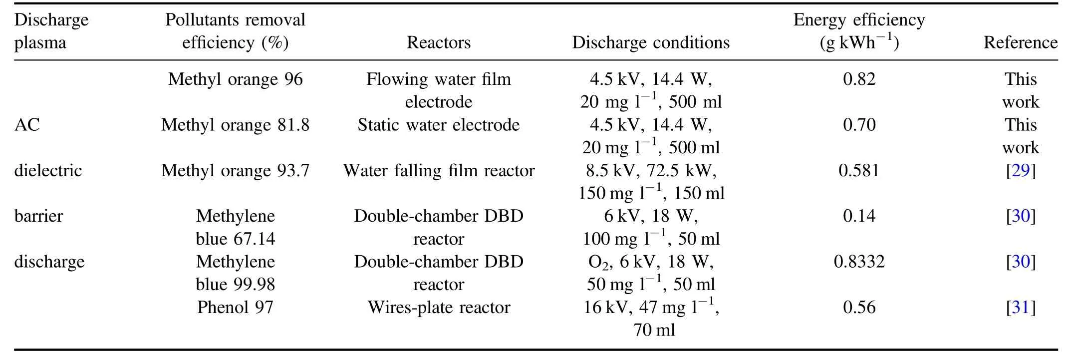
Table 2.Comparison of energy yields of similar reactors.
The comparison of energy yield between the plasma reactor in this study and similar reactors is shown in table 2.It can be seen from the table that the energy yield of the plasma reactor based on the flowing water film electrode reaches 0.82 g kWh?1, while the energy yield of the reactor based on the static water electrode is only 0.70 g kWh?1.The experimental data show that the plasma reactor proposed in this research can achieve high-efficiency degradation of methyl orange solution under air conditions.Compared with the static water electrode reactor, it has a higher decolorization rate and energy yield, which is better than the static treatment.
In addition,it can be seen from table 2 that energy yields are different under different reactors since the energy yield depends not only on the type of plasma reactor but also on various other factors, such as the concentration of the treatment solution, the removal rate, the input power, gasphase properties, etc.It is difficult to compare the performance of different reactors [32].Compared with other similar reactors, the plasma reactor proposed in this research is simple and can realize the effective degradation of organic solution in low pressure and low power air environment,which provides a new method for plasma water treatment technology.According to the test results, it is speculated that increasing the length and width of the sawtooth grooves or increasing the number of sawtooth grooves can increase the discharge area and the number of highly active particles, and achieve more efficient process in a short time, which has a specific reference value for industrial application.
6.Conclusion
In this paper, in the study of plasma water treatment, a nonuniform air gap is formed using a flowing water film electrode(<1 mm) and a sawtooth insulating dielectric layer to realize the dispersion glow discharge in atmospheric air.In addition,the flow characteristics of the water film electrode are analyzed.Combined with simulation, experiment, and detection,the discharge characteristics of the electrode structure and the treatment effect of methyl orange solution are studied.The specific conclusions are as follows.
(1) By constructing sawtooth grooves in the insulating layer, an uneven electric field distribution with large electric field intensity in the narrow gap and small electric field intensity in the wide gap is formed,especially a strong electric field area is formed on the lower surface of the water film.In addition, using the flowing water film as the discharge electrode and forming a closed air gap in sawtooth grooves, the possibility of active particles diffusing to the surrounding air is reduced, and effectively improves the utilization rate of active particles.When the aspect ratio of sawtooth grooves is 2,a diffuse glow discharge can be formed in the whole groove.
(2) The thickness of the flowing water film is controlled below 1 mm by controlling the mesh number, the inclined angle of the dielectric plate, and the inlet velocity of the liquid phase so that the active particles can react adequately with the organic matter before quenching.By utilizing the speed difference between the upper and lower surfaces of the flowing water film,the gas–liquid interface is replaced continuously,causing the plasma always to contact new methyl orange molecules to achieve uniform treatment.Also,the gas vortex in the groove can also effectively utilize the active particles away from the liquid surface,which improves the efficiency of single water treatment.
(3) The plasma treatment device with a flowing water film electrode is used.When the applied voltage is 4.5 kV,500 ml of 20 mg l?1methyl orange solution is treated,and the treatment time is 50 min, the pH value of methyl orange solution reduced slightly, and the decolorization rate reached 96%.
In this paper, a uniform and stable dispersive glow discharge is realized based on the flowing water film electrode.It achieves efficient degradation of methyl orange solution under atmospheric conditions, which provided a new method for plasma water treatment technology.
Acknowledgments
This research is financially supported by National Natural Science Foundation of China (No.51 577 011).
 Plasma Science and Technology2021年10期
- Plasma Science and Technology的其它文章
- Special issue on selected papers from CEPC 2020
- Surface treatment of titanium dioxide nanopowder using rotary electrode dielectric barrier discharge reactor
- Application study on plasma ignition in aeroengine strut–cavity–injector integrated afterburner
- Microanalysis of a ductile iron by microchip laser-induced breakdown spectroscopy
- Decontamination of infected plant seeds utilizing atmospheric gliding arc discharge plasma treatment
- The regulation of memory effect and its influence on discharge properties of a dielectric barrier discharge driven by bipolar pulse at atmospheric-pressure nitrogen
