Reversible waveform conversion between microwave and optical fields in a hybrid opto-electromechanical system?
Li-Guo Qin(秦立國) Zhong-Yang Wang(王中陽) Jie-Hui Huang(黃接輝)Li-Jun Tian(田立君) and Shang-Qing Gong(龔尚慶)
1School of Mathematics,Physics and Statistics,Shanghai University of Engineering Science,Shanghai 201620,China 2Shanghai Advanced Research Institute,Chinese Academy of Sciences,Shanghai 201210,China
3Department of Physics,Shanghai University,Shanghai 200444,China
4Department of Physics,East China University of Science and Technology,Shanghai 200237,China
Keywords: opto-electromechanical systems,photoelectric conversion,cavity quantum electrodynamics,optoelectromechanically induced transparency
1. Introduction
The efficient conversion of signals between the microwave at several gigahertz and the optical domain at hundreds of terahertz is a key technology in modern communication networks, especially in the connection between classical and quantum communication networks.[1–7]Over the past few decades, the information is processed electronically at microwave frequencies of several gigahertz.[2]Lots of engineered quantum systems in the microwave domain have been studied for quantum information processing, such as superconducting qubits and resonators,[8,9]electron spins of nitrogen–vacancy center in diamond,[10]and hyperfine states in ion trap qubits.[11]However,microwave frequency photons are difficult to transmit over long distances due to the thermal noise at the room temperature[8]and high loss~1 dBm?1with the optimal microwave cables at 10 GHz.[3]Photons in optical domain show complementary features with the microwave photons, such as ultra low transmission loss in the fibres below 0.2 dBm?1at telecom wavelength with the frequency 193 THz,[3]almost none thermal occupancy, highly efficient single-photon detectors,and long-lived quantum memories.[2]In addition,low decoherence and dissipation rates make optical photons as an ideal information carrier,which can be easily distributed between distant nodes in a quantum network via optical fibre and waveguide.[12,13]The disadvantage of the optical photon is the weak single-photon nonlinearity, which prevents the development of quantum gates.[14]These suggest the required techniques of bi-directional conversion of information between microwave and optical fields.
Such a converter with high-efficient conversion is useful to quantum information processing and quantum network.[2,3]The coherent conversion of photons has been proposed, including spin ensemble,[10,15]cavity quantum electrodynamics,[16]and the mechanical-membrane in electrooptomechanical systems.[1,7,17–20]Recent progresses including bi-directional operation,[21]coherent coupling,[22]and efficient conversion[23]make use of a mechanical oscillator as the transducer.
In cavity opto-electromechanical quantum system, a nanomechanical resonator (NMR) as a interface can couple a microwave device and an optical device on both sides of it. In such a hybrid device, we have reported a scheme of electro-optic waveform interconnect based on quantum interference.[24]In this work,we present a bi-directional conversion between microwave and optical fields in a hybrid electro-optomechanical device. As an interface, the NMR bridges quantum linking between microwave and optical cavities in the wide different frequency domains. In the hybrid device, we can find that the single optomechanically induced transparency (OMIT)[25–28]in the optical frequency domain is split into double-OMIT due to adding the optomechanical coupling in the microwave frequency domain,i.e., a new absorption peak appears in the OMIT window. The mechanism of double-OMIT is quantum interference with N-type energylevel from the coherent interaction of two kinds of photons and phonons in cavity optomechanics. By making use of this feature, we present a scheme of reversible waveform conversion between microwave and optical fields.The internal conversion efficiency in the device is determined by the microwave and optical cooperativities. The conversion bandwidth depends on the width of OMIT windows determined by the effective optomechanical coupling strength. Such a system can serve as a converter in hybrid quantum networks to connect optical and microwave fields.
Comparing with the other schemes, our model has the following advantages: (i) We obtain a bidirectional coherent conversion between the microwave and light signals,i.e., reversible conversion. (ii)The conversion can be obtained in the two different or same frequency domains. (iii) The conversion waveform is arbitrary. (iv)The hybrid opto-and electromechanical system is simple and compact for the integration and application.
2. Model and method

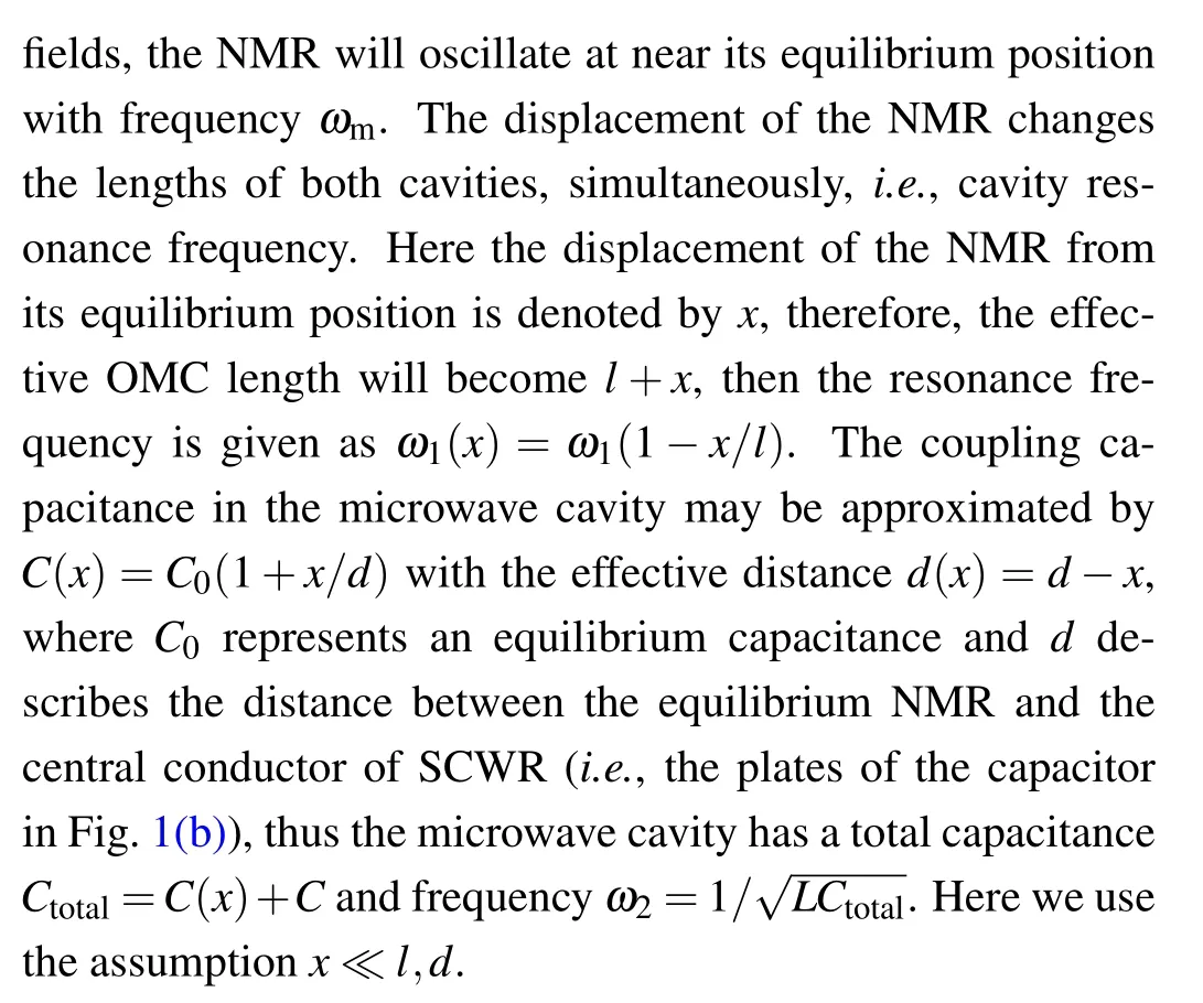

Fig. 1. Schematic diagram of reversible converter between microwave and optical fields in the hybrid of the opto-electromechanical system: (a) a nanomechanical resonator is coupled optomechanically to an optical cavity on the right and capacitively to a superconductig coplanar microwave cavity on the left, simultaneously; (b) equivalent circuit, where SCWR can be viewed as an LC oscillation circuit with the fixed inductance L and tunable capacitance as a sum of the constant capacitance C and the mechanically adjustable capacitance C(x).
The total Hamiltonian of the system can be written asH=Hfre+Hint+Hdri, which includes the free HamiltonianHfreof two cavities and the NMR,the interaction HamiltonianHintbetween NMR and two cavities,and the driven HamiltonianHdriof the two cavity-driven terms. Three Hamiltonians can be given respectively as


In the opto-electromechanical hybrid system, the resonant frequencies of the OMC and microwave cavity are usually much higher than the NMR’s frequency under the current experimentally conditions,i.e.,ωm?ω1,2. Based on the rotating transformation, the total Hamiltonian can be rewritten as

where?1=ω1?ωc,?2=ω2?ωw, and?pc=ωp?ωc. By introducing the dissipation and fluctuation noise terms,the dynamic equations of the system can be given by
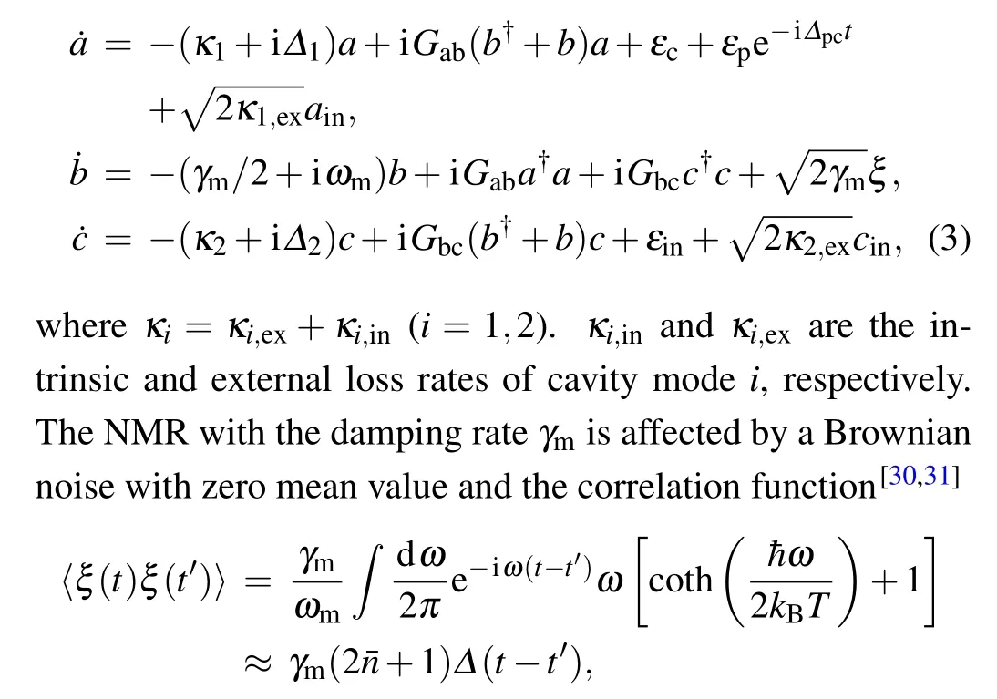
wherekBis the Boltzmann constant,Tis the temperature of the reservoir of the nanomechanical oscillator and=[exp(ωm/kBT)?1]?1is the mean thermal excitation number of the resonator. The cavity dynamics also depend on the cavity input noiseain(cin)with zero mean value.[32]Here,we are only interested in the mean response of the system,therefore the Heisenberg–Langevin noise operators can be reduced to their expectation values,i.e.,the quantum and thermal noise terms can be ignored.
In order to obtain the solutions of the Heisenberg–Langevin equations,we only care about in the linear response of the driven optomechanical system to the weak probe field.In the case of|εp|?|εc|,|εin|,the dynamical equations of the system can be linearized by assumingO=Os+?O(O=a,b,andc),[33,34]i.e., each operator of the system can be decomposed as the sum of its steady-state valueOsand a small fluctuationδO. By assumingεp→0 and setting all time derivatives to zero, the steady-state values of the system can be gotten from Eq.(3)as
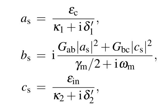
whereδ'1=?1?Gab(b?s+bs)andδ'2=?2?Gbc(b?s+bs)are the effective detuning of the optical and microwave cavities due the motion of the NMR, respectively. By substitutingO=Os+δOinto Eq. (3) and ignoring high-order nonlinear terms, the Heisenberg–Langevin equations of?Oare given by

where the effective coupling strengthGabs=GabasandGbcs=Gbccscan be enhanced by the input fields. By introducingδa=δ+e?i?pct,δb=δ+e?i?pct,andδc=δ+e?i?pct,we can ignore the fast oscillating terms ei2?pctand get the following equations:
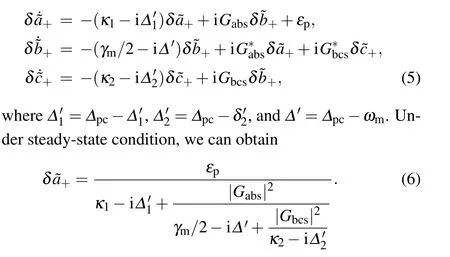
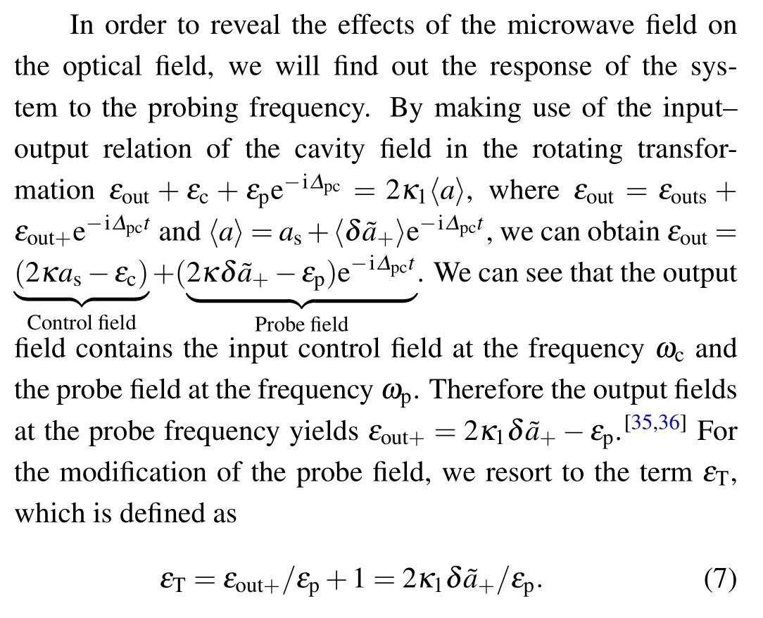
The real and imaginary parts ofεTshow the absorption and dispersion of the OMC system, respectively.[25]After some simplification, we can rewrite the term ofεTin a more intuitive relationship between the output probe field and the input microwave field as

3. Results and discussion
Now we investigate the conversion between the optical and microwave fields through NMR as an interface. To estimate the output field of OMC,the parameters are taken analogously to those of Refs. [29,37] for the NMR, that is,m=10 ng,ωm=2π×10.56 MHz,Q=3.6×10⁴,γm=ωm/Q,whereQis the quality factor of the NMR, for optical cavity of lengthl=1 mm and damping rateκ1=0.08ωm, driven by a strong pump field with the wavelengthλc=810 nm,for the microwave cavity with the frequencyωw=7.19 GHz,the damping rateκ2=0.01ωm,μ=0.09,andd=1.8 nm.
As shown in Fig.2,the absorption Re(εT)and dispersion Im(εT)of the output field are plotted as functions of?/ωmfor different powers of driven fields by setting?'1=?'=?'2=?,i.e., the red detuningδ'1=δ'2=ωm. We can find the OMIT windows from absent to single to double,which can be understood from the interference based on the level configuration in Fig. 3.[38]If the OMC is not driven by the strong pump fieldεc,figure 2(a)shows the usual absorption and dispersion of the optical field with no transparency window.The output field becomesεT=2k1/(k1?i?),which only depends the OMC decayκ1and the detuning?.However,if the quality factor of the OMC is sufficiently high, the transparency can be opened up by the cavity vacuum,i.e., the vacuum Rabi-splitting, which can lead to vacuum-induced transparency(VIT),[39]this case is not considered here. When the OMC is driven by the strong pump field and without the microwave field, the output field can be rewritten as

which has the standard form of OMIT due to the destructive interference between the probe field and the anti-Stokes field(Gabs)generated by the pump pulse,as shown in Fig.2(b).The width of the transparency window depends on the intensity of the effective coupling|Gabs|2in the optical cavity, which can be adjusted by the input fields.[40]

Fig. 2. The absorption Re(εT) (blue-solid line) and dispersion Im(εT) (reddashed line)as a function of the detuning ?in the different cases(a)Pc=0;(b) Pc =60 mW, Pm =0; (c) Pc =60 mW, Pm =0.6 μW; (d) Pc =60 mW,Pm=24μW.
Further, when the optical and microwave fields interact simultaneously with NMR, the behavior of the probe output field becomes the double-OMIT,[36]which is caused by the additional coupled microwave field. Its real and imaginary parts are shown in Figs.2(c)and 2(d). A new absorption peak appears inside the transparency window in Fig. 2(b) due to the effect of the destructive interference.[38]The double-OMIT can be explained by theN-type energy level configuration in Fig. 3. When the NMRbis coupled to the microwave cavitycvia the microwave optomechanical interaction, which is involved in the interference process, this microwave optomechanical interaction destroys the OMIT and splits one transparency window into two,i.e., two dips appear as shown in Fig.2(d). In addition,we can find that the middle new absorption peak become high as the power of microwave input field increases from Figs.2(c)and 2(d).

Fig.3. Energy level structure of the simplified system. The number states of photons and phonons are denoted by No,m and n,respectively. The effective optomechanical coupling strength between|No+1,Nm,n〉and|No,Nm,n+1〉in the optical domain is Gabs, and the effective optomechanical coupling strength between|No,Nm,n+1〉and|No,Nm+1,n〉is Gbcs.
When?=0 with the red detuning and the constantGabs,we can construct the interconnection between microwave and optical fields and rewritten Eq.(8)as

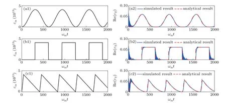
Fig. 4. Numerical and analytic results of the waveform conversion. Panels (a1), (b1), and (c1) show the input cosine, square, and sawtooth microwave waveforms injected into SCWR,and panels(a2),(b2),and(c2)show the numerical and analytic results of the cosine,square,and sawtooth waveform conversions,respectively. The other parameters are the same as those in Fig.2(b).
whereGbcs=Gbcεin/(κ2+iωm) is proportional to the input microwave field. Thus, we obtain an analytic expression of the relationship between the output field of OMC at the probe frequency and the input microwave field. Using this interconnect,we can generate an arbitrary waveform modulation of the optical field by adjusting the corresponding input microwave field. In the path, the input microwave field is transferred to the output of OMC alongεin→c →b →a →εT, where the transmission amplitude is changed, but its waveform can be kept. To demonstrate the ability of the proposed scheme to transfer waveform between both different frequency signals,we give the numerical simulation results of Eq.(5)with?=0,the initial timeδ(0)=δs,?(0)=0, andδ(0)=0, as shown in Fig. 4. For keeping high fidelity of the conversion from Eq. (10), the approximate conditions need be satisfiedγmκ2?2|Gbcs|2?2|Gabs|2κ2/κ1,i.e., a high quality NMR and optical cavity. Further equation (10) can be approximatively rewritten as

which is a one-to-one correspondence between the microwave field and the output probe field. Thus the waveform of the output probe field follows the waveform of the input microwave field,i.e.,a waveform conversion or interconnect.
For the transmission waveforms,we choose the standard and general cosine,square,and sawtooth waveforms as the input waveforms injected to SCWR,as shown by the solid lines in Figs.4(a1),4(b1),and 4(c1). Then,by using the numerical simulations, we obtain the corresponding transmission waveforms, indicated by the blue solid lines in Figs. 4(a2), 4(b2),and 4(c2). Based on Eq. (10), the corresponding analytic results of the output field are shown by the red dashed lines in Figs. 4(a2), 4(b2), and 4(c2). We can find that the envelopes of the simulation results are in good agreement with the waveforms of the analytical results,and approximatively follow the waveform of the input microwave field. The differences between both simulation and analytical results mainly originate from the transient process, which can not change the whole evolution envelope.
In addition,if a strong control field and a weak probe field are injected into SCWR from the right side of the device,and a strong optical field is injected OMC from the left side of our device, that is, the positions of the modeainterchanges with that of the modecin the total Hamiltonian of our system.From Eq.(1),we can see that the positions ofaandcare symmetric in the Hamiltonians of before and after interchange positions of modesaandc, therefore the conversion waveform of optical to microwave frequency can be achieved based on the same method. Therefore,in this paper,we propose a feasible theoretical scheme for an arbitrary-waveform reversible conversion between microwave and optical wave. This scheme can be used to realize an arbitrary-waveform modulator between two fields in the different frequency domains.
To measure the conversion efficiency,we can use the conversion efficiency present by Tang.[8]To introduce the input and output of modesaandcinto the equations of motion,we can give the reasonable assumptions including the resonance?=0,negligible the Brownian noise to NMR,the small cavity inputainandcin. Then equation(5)can be rewritten as

From Figs.2(c)and 2(d)and Eq.(8),we can find that the bandwidth of the output field at?=0 depends on the width of induced window,i.e., the effective microwave-mechanical coupling strengthGbcsbased on quantum interference. Therefore the bandwidth of the conversion is determined by the width of OMIT window depended on the effective optomechanical coupling strengthGbcs, which can be modulated by the input microwave field and the quality factor of SCWR.When the waveform conversion from optical to microwaves is performed, and vice versa based on the same mechanism.For bidirectional conversion,the bandwidth of the conversion depends on both effective optomechanical coupling strengthsGabs andGbcs.
4. Conclusions
In summary,we proposed a scheme to realize a reversible optical to microwave waveforms conversion in two different frequency domains by a hybrid opto-electromechanical system based on quantum interference. The analytically convertive expression of one-to-one correspondence between the microwave field and the optical field has been given. The proposed scheme may built a bridge to interconnect two different frequency domains,i.e., bi-directional waveform transfer.The internal conversion efficiency is determined by the microwave and optical cooperativities. The conversion bandwidth depends on the width of OMIT windows determined by the effective optomechanical coupling strength. It will be expanded into the field of information transmission and coding,linking low-loss transmission optical signals and deft microwave technologies to achieve complementary advantages of the microwave and optical waves. This scheme may have potential applications in future communication and signal processing systems.
——小記書家廖中陽先生
- Chinese Physics B的其它文章
- Quantum computation and simulation with vibrational modes of trapped ions
- ?∞state estimation for Markov jump neural networks with transition probabilities subject to the persistent dwell-time switching rule?
- Effect of symmetrical frequency chirp on pair production?
- Entanglement properties of GHZ and W superposition state and its decayed states?
- Lie transformation on shortcut to adiabaticity in parametric driving quantum systems?
- Controlled quantum teleportation of an unknown single-qutrit state in noisy channels with memory?

