Suppression of ferroresonance using passive memristor emulator
S Poornima
Electrical Engineering Department,Anna University,Chennai-600025,India
Keywords: ferroresonance,memristor emulator,passive components,single-phase transformer
1. Introduction
The requirements for forming a ferroresonance circuit are saturable inductance, capacitance, source of supply, and low loss load. The lightly loaded or no-load transformers possessing all these requirements are often susceptible to ferroresonance. The dielectric failure and thermal stress in a transformer due to this phenomenon may propagate into the network. The overvoltages and overcurrents are developed due to the ferroresonance range between 2–4 per unit. Frequent ferroresonance phenomena degrade the metal oxide varistors of lightning arresters,causing them to lose their potential performances gradually. Though many mitigation methods have been discussed so far, many of them did not exist in practice due to several reasons.
The ferroresonance phenomenon may take place when the inductive core of the transformer gets saturated and resonates with the system capacitance. Many analytical models and experiments were made to study its occurrence.[1]It generally occurs under asynchronous phase switching conditions.Underground cables rated above 25 kV experience more ferroresonances when switching on lightly loaded transformers.
Arresters employed to protect the cables might fail fiercely during phase-by-phase switching. Power transformers, reactors, voltage transformers, series-compensated transmission lines, transformer-terminated lines, oversped generators, series-compensated high-voltage direct current (HVDC)converters,ungrounded/unbalanced operation of transformers,etc.resonate with their system capacitance in the nonlinear(saturation) operation region, generating ferroresonance.[2–5]Recently, voltage transformers of a microgrid consisting of photovoltaic(PV)grids and wind turbines are exposed to ferroresonance during switching and pole breakdowns.[6,7]The literature shows that the ferroresonance phenomena will exist with any kind of technology in power systems. The phenomenon is realized in terms of frequency as fundamental,subharmonic,quasiperiodic,and chaotic modes. The periodic and aperiodic ferroresonance mode ferroresonance can be induced in a series LC circuit by varying the circuit capacitance,supply voltage and switching angle.[8]The classical jump process between normal to any of the four modes depends on the initial conditions of the circuit.[9]Many studies have been conducted to identify and suppress the modes of ferroresonance.The overvoltage or overcurrent due to this nonlinear resonance can be taken care of by the proper design of the resistance,arrester, Thyristor circuits, guard relays,etc.[10–13]A lot of literature explains that the suppression circuit has its own merits and demerits. The investigation studies on damping circuits of ferroresonance imply that a nonlinear system can damp more effectively than a linear one.
In this paper, the behavior of an upcoming memristor technology-based emulator is used to suppress the fundamental ferroresonance. The nonlinear memristive device can be connected as a load to a transformer. The pinched hysteresis characteristics of the memristors have proved their nonlinear performance. They offer good resistance and help to suppress the ferroresonance as efficiently as the linear resistors. Also,they can be used to identify abnormal conditions and switch ON the load circuits. A preliminary work on ferroresonance mitigation using memristor emulators has been done in a low power transformer and the same concept has been extended to medium voltage transformers in other papers of the same authors.
2. Inception of ferroresonance
The failure results of substation equipment imply the need for ideal modeling and investigation of power systems.[14]The ferroresonance phenomenon is realized by modeling through using software like ATP/EMTP, PSCAD, MATLAB,PSPICE,etc.The analytical methods like Bifurcation diagrams, Poincare, phase-plane,etc.explicitly show the transition from periodic state to chaotic state andvice versa.[15,16]Many practical failures due to ferroresonance are examined by these methods. The series LC circuit performance is influenced by the coefficient of inductance coupling and circuit parameters.[17]The nonlinear resonance could induce intentionally by using the Rudenberg graphical approach.[18]The approach implies that in a series LC circuit, the intersection of the saturation characteristics of inductor and capacitor voltage curves provides the information about the ferroresonance modes.[19]
The inception of ferroresonance is expected at the transition point between normal state and ferroresonance operating state. The jump-up effect during fundamental ferroresonance in the transformer gets initiated at the point of core saturation.The polynomial relation between magnetizing current (imag)and core flux(?)can be expressed as

Application of Kirchhoff’s law to the system yields

Here,ω0andβdenote the frequency and switching angle of the source,respectively. The winding and core loss resistance of the transformer are represented byRtandRmrespectively. The number of turns in the transformer winding and the circuit breaker grading capacitance can be denoted asNandCrespectively. The core flux in the transformer will be

whereQdenotes the amplitude of core flux, andαrepresents the phase angle between the core flux and source voltage. The supply voltage at which jump-up occurs can be found by applying the describing function to Eq.(3)and solving the voltageV0in Eq.(2)as[20]

whereBn=cosn(ωt+α)andBn?1=cosn?1(ωt+α)are used for further simplifications.
The jump up and down value of supply voltage can be determined from the maximum and minimum value of the voltageV0obtained by using Eq.(4). The parametersC1,Cn,Rt,andRm, are used to predict the occurrence of ferroresonance as jump voltage value by using Eqs. (1)–(4). The simulation values can be validated by using the limits of the estimation parameters listed in Table 1.annealing (ASA),etc.can be used, besides the solution of Eq.(4). As the jump voltage estimation parameters have fixed limits,the ASA technique is chosen for its advantages over the PSO.The optimization functionFnis given by

where the subscripts‘s’and‘e’indicate the values of simulation and experiment,respectively.
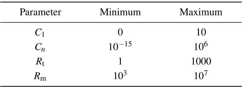
Table 1. Limits of estimation parameters.
3. Memristor emulator
Applying the parameter values to Eq. (5), the jump-up and down values due to fundamental ferroresonance in a transformer can be predicted. The limits of the transformer parameter will vary according to its power rating and voltage rating.
For any transformer modeling,an optimization technique such as particle swarm optimization(PSO),adaptive simulated
A memristor is the fourth fundamental, passive twoterminal element relating to electric charge and flux linkage. In 1971, Chua introduced this element with its nonlinear behavior.[21]It exhibited peculiar pinched hysteresis characteristics and dynamic output. The pinched hysteresis curve will increase or decrease according to the polarity of the voltage.[22]
The memductance of the emulator decreases when the supply frequency is increased to kHz.[23]The memristive element when implemented in a chaotic circuit generates varying amplitude and frequency over time. The chaotic memristor exhibits unique dynamic behavior and homogenous multistability with respect to input change.[24]
Extensive research has been motivated since 2008 by which transistors can be replaced by memristors in the future.Nonvolatile memory, reconfigurable nanoelectronic systems,stateful logic,and neuromorphic synaptic networks will be attractive applications of memristor.[25]Though the element is not yet available commercially,emulators imitating its properties are evolved by using operational amplifiers,Arduino,motors,etc.[26–29]The employment of real memristors will revolutionize electronics,similar to the scenario of the invention of transistors in earlier days.
3.1. Passive memristor emulator
Controlled sources such as operational amplifiers,IGBTs,MOSFETs,etc.can be replaced by passive elements that emulate memristive behavior.[30]The main limitation of those emulators is that they require additional supply to activate them. Generation of memristor emulators with passive elements which overcome the mentioned constraint may lead the emulators to possess various applications. With such emulators, memductors and memcapacitors can also be developed.The voltage-controlled memristor has its port expressions as given by

wheregandfare nonlinear functions of the state variablexand the voltagevof the memristor emulator. The functiongrepresents the memductance, which is governed by the state variable and the voltage. Hence,this dependence of memductance leads to pinchedv–icharacteristics. In this work, the passive memristor emulator proposed in Ref. [28] is used to identify the suitability as a nonlinear load to a transformer.The formulations proposed in Ref.[28]as a memristor emulator helps to identify the memristance value required to mitigate ferroresonance in this study. The JFET-based passive memristor emulator (PME) shown in Fig. 1 has the advantage of reduced circuit complexity. The circuit elementsR1,R2,Cof the JFET J310 represent the resistance to drain, resistance to the gate,and capacitance to source connections externally,respectively. The elementR2limits the current entering into the gate terminal. The applied voltageVgenerates current such that the current through the elementR1is negligible compared with the current entering into the drain terminal. The combination of elementsR1andCforms an integrator circuit which integrates the voltage across the drain and source terminal of the JFET. The lossy integrator generates its output voltage at the cutoff frequency

The voltage across the elementCis considered as the state variable controlling the drain current and conductance by its nonlinear relation with them. If the conductance becomes completely independent of the applied voltage, the JFET exhibits memristive behavior under the influence of the state variable.[26,28]Thus,the above circuit emulates the memristor characteristics as it possesses nonlinear transfer characteristics and lossy integration.
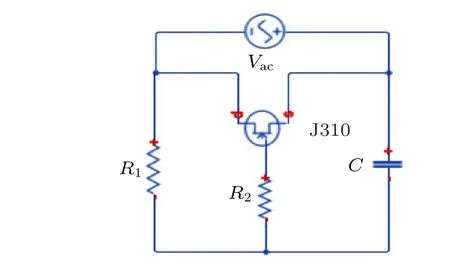
Fig.1. Passive memristive emulator.
The supply voltage is applied to the drain and source terminals of the JFET,whose equivalent circuit is shown in Fig.2.The current through the elementR1is the sum of the currents through the elementsR2andC. At node V1,

If the output voltage of the integrator is considered asVgs,then it can be obtained as

Then the current through the drain terminal is calculated from

where the value ofgmandrdare available in the manufacturer’s datasheet. Equation (12) satisfies Eq. (6) as theVgsandgmare the representations of the state variable (integration voltage) and the supply voltage, respectively. Similarly,equation(11)satisfies Eq.(7)for the same reason.
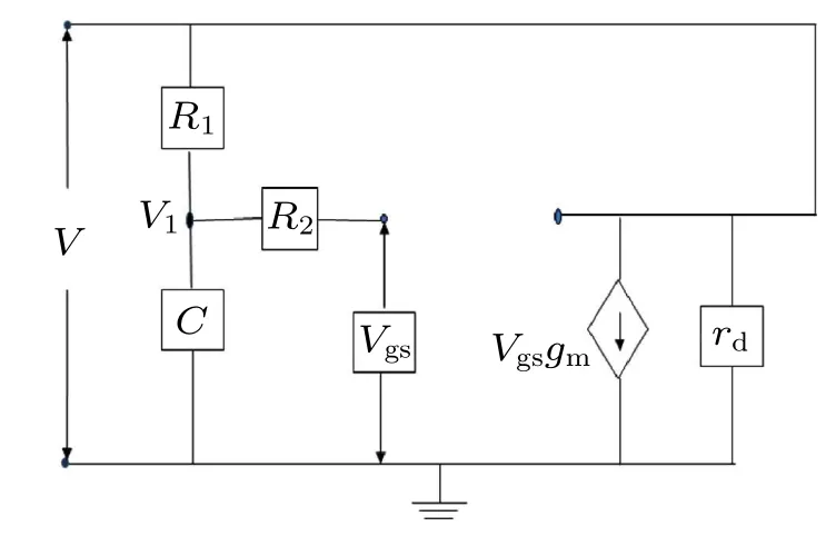
Fig.2. Equivalent circuit of PME.
3.2. Multisim model of PME
The passive memristor emulator is designed by using the common-gate amplifier J310 in Multisim software[31]as shown in Fig. 3. Its ON resistance is enough to provide the necessary load for the mitigation of ferroresonance.
The voltage applied across the drain and source terminal supplies the current such that the drain resistance and source capacitance perform the function of an integrator at the frequency of 50 Hz. The current is measured across the 10-?resistor and plotted against the supply voltage. The voltage and current data at various amplitudes and supply frequencies are obtained and plotted using Matlab.
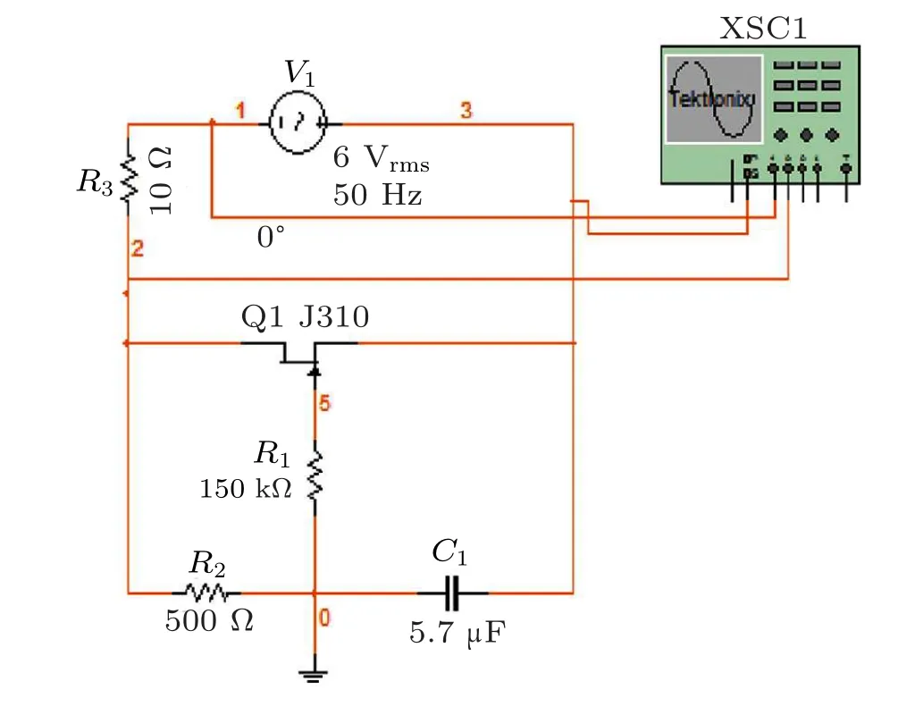
Fig.3. Multisim model of PME.
The supply voltage is varied from 1 V to 8 V gradually in steps of 1 V.Figure 4 shows that the area of the hysteresis lobe increases with the supply voltage. The pinched nature of hysteresis occurs at non-zero coordinates. It implies that the zero crossings of the applied voltage and the current does not occur simultaneously.
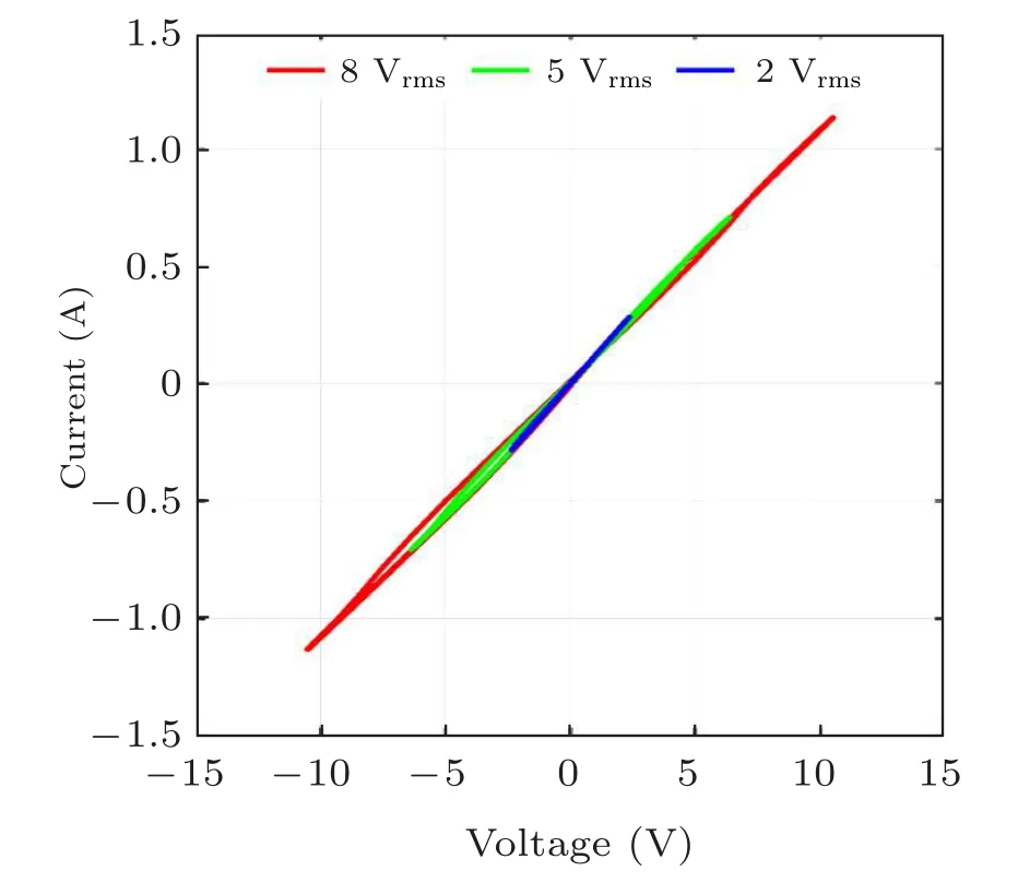
Fig.4. Lissajous pattern of PME.
The pinched nature characteristics also depend on supply frequency. Figures 5(a) and 5(b) show that the areas of the hysteresis lobes in the first quadrant and the third quadrant are both inversely proportional to the value of supply voltage at high frequency. Thus,the curve becomes linear at high frequencies.[32]The supply frequency values are 1 Hz,10 Hz,50 Hz,1 kHz,and 10 kHz,respectively. The obtained curves are asymmetrical in both quadrants at very low frequencies and possess nonlinear nature.The hysteresis loses its pinching nature at 1 kHz and becomes linear at 10 kHz. The frequency dependency of the memristor emulator determines the shape of hysteresis characteristics in the first quadrant and the third quadrant. While varying the frequency,the voltage across the capacitor decreases from 7.85 V(at 1 Hz)to 0.77 V(at 1 kHz).While the capacitance of the PME varies from 1 pF to 1 F at 50 Hz,the voltage across the capacitor is found to be minimum at 1μF.
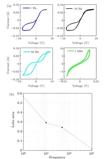
Fig. 5. (a)V–I curve and (b) hysteresis area of PME at different frequencies.
4. Experimental validation
The ferroresonance and memristor arouse the interest of researchers who try to make a circuit to realize them. The stray capacitance in parallel to saturable inductance may create ferroresonance very often.[33]The switching ON and OFF operation of circuit breaker capacitance resonating with saturated inductance of the transformer are considered here.
A transformer rated at 3 VA, 230 V/6 V is chosen, as the accuracy of the transformer is similar to that of the voltage transformer. The preliminary transformer data is obtained from the open circuit test and short circuit test.The solution of Eq.(4)gives the jump-up and jump-down at the supply voltage of 85 V and 62 V,respectively.
Similarly, the primary voltage and current of the chosen transformer experiences 1.6 times the normal values. While reducing the supply voltage to 0 V gradually, the jump-down phenomenon is observed in the secondary voltage at a supply voltage of 60 V.The jump phenomena can be understood from Fig. 6. The analytical values are then improved by the optimization technique through using Eq.(5). Using the ASA technique, the solution of Eq. (5) gives an onset voltage of ferroresonance as 80 V. Also, the jump-down voltage is observed at a supply voltage of 61 V.The jump phenomena and the distorted waveform indicate the occurrence of fundamental ferroresonance.
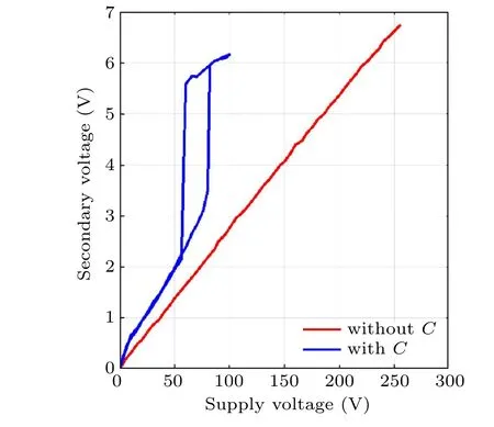
Fig.6.Transformer secondary voltage with and without ferroresonance.
4.1. Realization of memristor characteristics
The physically developed PME shown in Fig.7 possesses the fingerprints of an ideal memristor. According to Chua,[34]the fingerprints are as follows.
(i)The voltage–current characteristic of the circuit has a pinched’8’loop.
(ii) As the frequency increases, the pinched characteristics vanish and become linear at high frequency.
(iii)The area of the pinched loop increases with the magnitude of the supply voltage.
(iv) The memristance of the device remains ON until it gets triggered the next time.
The above characteristics are obtained successfully by the PME circuit shown in Fig. 8. The AC voltage is supplied to the circuit by using a function generator. The circuit is developed to work at 50 Hz as it is designed as a load for the transformer. The gate resistance‘R2’,the drain resistance‘R1’,and the gate–source capacitance‘C’are determined to be 150 k?,500 ?,and 5.7μF,respectively,to meet the load requirements.With the chosen values, the pinched characteristics obtained are similar to those from the Multisim.
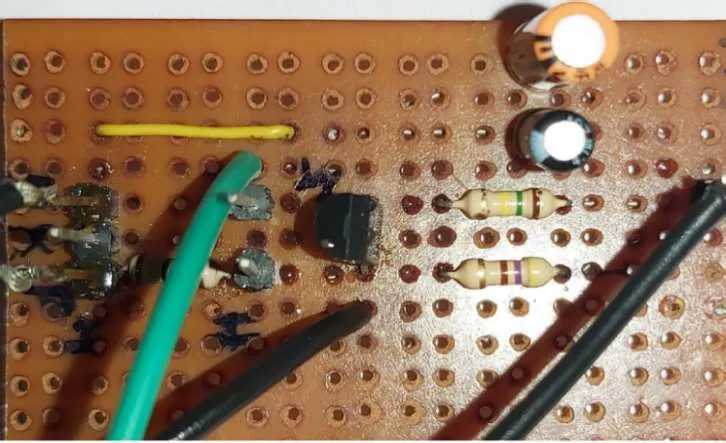
Fig.7. Fabricated PME.
4.2. Suppression of ferroresonance with resistor and PME
The fundamental mode and chaotic mode are the frequent events of ferroresonance in the transformer. A load equal to or more than 10% of the rated value is enough to suppress the fundamental mode of ferroresonance.[35]Accordingly,a resistor of 75 ? and a passive emulator are used individually to suppress the sudden increase in voltage. The retained magnitude and shape of the secondary voltage has evidenced the suppression of ferroresonance. The mitigation effect similar to the linear resistor is experienced by using the emulator. The data obtained from the oscilloscope DPO2022B is processed in the Matlab software. The drain current is measured as a voltage across a 10-? resistor connected in series with the drain terminal of the JFET.The mitigation performances of the passive memristor emulator and linear resistor are analyzed by fast Fourier transform(FFT).
5. Results and discussion
The memristor emulator, mimicking the ideal characteristics, is discussed in terms of its pinched hysteresis characteristics. The nonlinear resistor is found to have impressive applications in the protection of transformers.[36]One such an application can be the suppression of ferroresonance in inductive voltage transformers. Though a linear resistor is used as a ferroresonance suppression device usually,the performance and lifetime of the transformer degrade over repeated occurrence. The proposed nonlinear resistor is compared with the existing mitigation technique.
5.1. Hardware development of PME
The developed passive emulator circuit, along with the practical concerns, has the memristor characteristics as listed below.
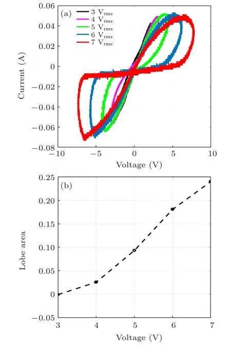
Fig.8. (a)Pinched hysteresis and(b)lobe area at different supply voltages.
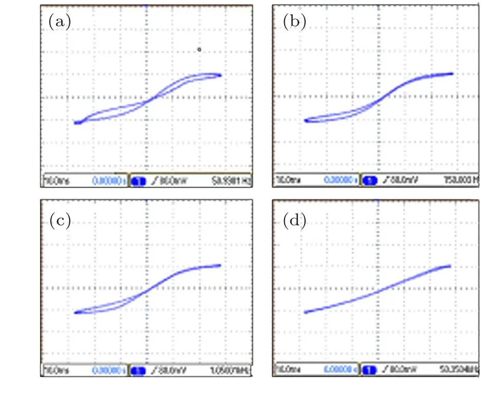
Fig.9.Pinched hysteresis of the passive memristor emulator at frequencies: (a)50 Hz,(b)150 Hz,(c)1 kHz,and(d)50 kHz.
(i) The hysteresis lobe area increases as the supply voltage increases from 3 V to 7 V as shown in Fig.8.
(ii) Owing to parasitic effects, the characteristics do not pass exactly through the origin as shown in Figs.9(a)–9(c).
(iii) It possesses nonlinearity at a required frequency of 50 Hz.
(iv)The first quadrant lobe area and the third one are symmetrical at 50 Hz.
(v) The hysteresis curve loses its pinching nature at 50 kHz as shown in Fig.9(d).
(vi) The initial resistance of this circuit is found to be 350 ?.
(vii)It does not have a nonvolatile property.
5.2. Onset of ferroresonance
The fundamental mode of ferroresonance can be induced in a transformer by using the Rudenberg graphical method. A capacitance,resonating with transformer saturated inductance,develops jump-up and jump-down phenomena at the supply voltages of 80 V and 60 V,respectively.The secondary voltage of the transformer experiences a jump-up from 3.5 V to 5.6 V while the primary voltage increases from 125 V to 215 V.
The primary current is raised from 4.5 mA to 16 mA.The jump-up event and the distorted waveform of the secondary voltage prove the occurrence of fundamental ferroresonance.Similarly, the jump-down phenomenon is realized as the secondary voltage decreases from 5.4 V to 2.7 V.As the primary voltage decreases from 205 V to 110 V, the primary current also drops down from 13.6 mA to 4 mA.
5.3. Mitigation of ferroresonance using passive memristor emulator
The memristor emulator developed is validated against the Multisim software. The memristor emulator is designed to draw the current necessary to suppress the ferroresonance of the transformer. The developed emulator is connected as a load to the transformer. During ferroresonance, the emulator draws a current around 30 mA,such that the secondary voltage decreases from 5.6 V to 2.93 V. Figures 10 and 11 show the suppression performance of the memristor when connected as a load to the transformer. The pinched point slides down to the third quadrant. The hysteresis lobe areas are asymmetrical. Though the linear resistor mitigates the ferroresonance,the passive emulator proves better in performance. While the resistor recovers the secondary voltage by 80.86%, the proposed PME recovers the secondary voltage by 83.71%.
The mitigation performance of PME is compared with those of memristor emulators developed by using the current conveyor integrated circuit and saturated solution of CuSO4.[37,38]The grounding memristor emulator(GME)built by using an analog multiplier AD633 and current conveyor IC emulates memristor properties and the requirements for an additional direct current power supply for excitation. The liquid memristor emulator(LME)consists of saturated CuSO4electrolyte with asymmetrical copper electrodes.[39]All the developed three memristor emulators are connected individually as a load during ferroresonance. The nonlinear resistance contributed by the emulator circuits dampens the ferroresonance oscillations effectively and prevents retriggering. The recovery performance of the proposed PME is better than the others.
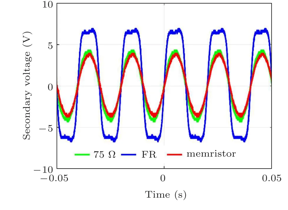
Fig.10. Mitigation of ferroresonance with resistor and passive emulator.
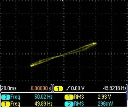
Fig.11. Pinched characteristics of PME during mitigation of ferroresonance.
The secondary voltage and current of the transformer during mitigation hold periodicity and the FFT analysis indicates the presence of harmonics in addition to 50 Hz. The conventional technique is designed to damp only a certain frequency mode. The fundamental ferroresonance and its mitigation voltage possess the fundamental frequency(50 Hz)along with 150-Hz, 250-Hz, and 350-Hz components. While the transient signal has a significant magnitude of frequency component,the mitigated voltage shows the controlled harmonics.Table 2 shows the FFT coefficient values of secondary voltage in all cases.Apart from the damping effect,the proposed PME proves that the%THD(total harmonic distortion),fundamental, third harmonic, and fifth harmonic components are better controlled than the linear resistor.
The nonlinear resistance of the memristor emulator also damps subharmonic ferroresonance oscillations effectively.[40]Thus, the memristor emulator could be a mitigation device for periodic as well as non-periodic modes of ferroresonance in the near future.
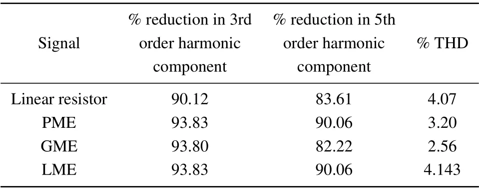
Table 2. Recovery performances of resistor and memristor.
6. Conclusions
The upcoming memristor technology is found to possess a lot of applications in emulating electronic circuits. An attempt is made to use a memristor emulator circuit for mitigating the fundamental ferroresonance in a low power transformer prototype.
(i)A memristor emulator circuit using JFET is chosen according to the requirements of transformer.
(ii) The simulation and hardware results of the passive emulator ascertain the memristor characteristics.
(iii)The mitigation of fundamental ferroresonance is validated in terms of secondary voltage and its harmonic components.
(iv) The experimental results prove the better mitigation performance of the memristor emulator than that of the linear resistor.
The memristor emulator can be refined further to handle chaos too. The same effort has also been made to implement the medium tension transformers by the authors.
- Chinese Physics B的其它文章
- Coarse-grained simulations on interactions between spectrins and phase-separated lipid bilayers?
- Constraints on the kinetic energy of type-Ic supernova explosion from young PSR J1906+0746 in a double neutron star candidate?
- Computational model investigating the effect of magnetic field on neural–astrocyte microcircuit?
- Gas sensor using gold doped copper oxide nanostructured thin films as modified cladding fiber
- Exact explicit solitary wave and periodic wave solutions and their dynamical behaviors for the Schamel–Korteweg–de Vries equation?
- Suppression of ice nucleation in supercooled water under temperature gradients

