A combined virtual impactor and field-effect transistor microsystem for particulate matter separation and detection
Yanna Li, Muqing Fu, Wei Pang, Ye Chang,,a) and Xuexin Duan,a)
ABSTRACT Ambient suspended particulate matter (PM) (primarily with particle diameter 2.5 μm or less, i.e., PM2.5) can adversely affect ecosystems and human health. Currently, optical particle sensors based on light scattering dominate the portable PM sensing market. However, the light scattering method has poor adaptability to different-sized PM and adverse environmental conditions.Here,we design and develop a portable PM sensing microsystem that consists of a micromachined virtual impactor(VI)for particle separation,a thermophoretic deposition chip for particle collection,and an extended-gate field-effect transistor(FET)for particle analysis.This system can realize on-site separation,collection,and analysis of aerosol particles without being influenced by environmental factors.In this study,the design of the VI is thoroughly analyzed by numerical simulation,and mixtures of different-sized silicon dioxide(SiO2)particles are used in an experimental verification of the performance of the VI and FET.Considering the low cost and compact design of the whole system,the proposed PM analysis microsystem has potential for PM detection under a wide range of conditions, such as heavily polluted industrial environments and for point-of-need outdoor and indoor air quality monitoring.
? 2021 Author(s). All article content, except where otherwise noted, is licensed under a Creative Commons Attribution (CC BY) license(http://creativecommons.org/licenses/by/4.0/). https://doi.org/10.1063/10.0003447
KEYWORDS Particulate matter, Microsystem, Virtual impactor, 50% cutoff diameter, Field-effect transistor
I. INTRODUCTION
Aerosol particulate pollution has serious impacts on ecosystems and human health. The most obvious direct impact of particulate matter (PM)1suspended in the atmosphere is a reduction in visibility,2,3causing a high degree of inconvenience in daily activities.In addition, PM of diameter 2.5 μm or less (PM2.5) is particularly harmful,since it can adsorb large numbers of microorganisms(both bacteria4,5and viruses6,7) with potentially harmful effects on the respiratory system and elsewhere in the human body.8-10
The generation and transport processes of atmospheric PM pollution are complex.11,12Therefore, effective technical means are needed to realize real-time and online monitoring of aerosol particles. At present, conventional monitoring of atmospheric pollutants depends on national monitoring networks.13Although such networks cover most regions, they still provide insufficient information. Besides, the data that are collected cannot reflect the source and formation process of PM pollution in a timely and accurate manner. The limitations of these networks have been shown in the context of a number of practical environmental problems,such as the identification of key pollutant discharging enterprises,firework and firecracker activities, straw burning areas, and other specific sources of PM pollution. To enlarge the detection range,portable particle sensing instruments that enable onsite PM detection have been developed in recent years. For instance, sensors based on a light scattering mechanism determine particle concentration by measuring the scattered light from a combination of all the particles in one or more angles.14,15Such devices have sufficient sensitivity to detect PM; however, their responses are dominated by large particles and are therefore strongly dependent on particle size distribution. Although calibration can be applied to validate measurements of different-sized particles, it is still sensitive to deviations in particle size,shape,and composition from those of the calibration aerosols. Besides, light scattering is also affected by environmental factors such as humidity and temperature.16,17Indeed, for measurements to be adaptable to different situations,it is necessary for light-scattering instruments to undergo multiple calibrations.18
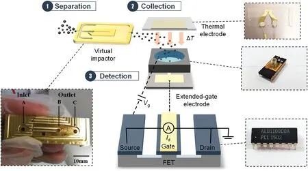
FIG. 1. Schematic of the mechanism of the PM analysis microsystem.The insets show photographs of the micromachined VI, the thermal electrode, the front-end extended-gate chip, and the back-end FET chip.
To develop a reliable method for use under complex PM detection conditions, we have designed and developed a microsystem based on a PM separation device and a PM detection module(Fig. 1). Here, a miniaturized virtual impactor (VI) with a 50%cutoff diameter of 2 μm is used to separate mixed particles based on inertial classification. The separated PM2 is collected and analyzed by an extended-gate field-effect transistor(EGFET)in which a gold auxiliary electrode is connected to the gate terminal of a conventional metal-oxide-semiconductor field-effect transistor(MOSFET),which can directly measure the charges of the deposited PM.19Both the VI and EGFET can be mass-producible and are replaceable.Our results suggest that the proposed microsystem has potential for accurate real-time analysis of PM2 containing mixed particles in complex environments.
II. SYSTEM DESIGN
Figure 1 illustrates the mechanism of the PM analysis microsystem.First,different-sized PMs are introduced into the VI,in which particles are separated immediately into different flow channels(the separation process).The separated particles are then deposited on a water-soluble gelatin membrane by thermophoresis (the collection process). The gelatin membrane is then transferred and dissolved in a liquid chamber, where an off-chip EGFET is used to monitor the current variation based on the direct coupling of particle charges due to adsorption of the particles on the electrode(the detection process).20-22Because of the physical separation between the sensing area and the measurement system, the sensing electrode of the off-chip EGFET can be replaced,with the FET device itself being reused,which significantly reduces the cost of the sensor.
As one of the most popular techniques for ambient PM separation, VIs have been extensively discussed in the literature.23-25Owing to their high separation efficiency,low particle loss,and relatively small size,26they possesses enormous potential for PM detection.Figure 2(a)shows a schematic of a VI.The inlet air flow carries both the coarse and fine particles,which are accelerated through an injection nozzle.The coarse particles with higher mass tend to follow the minor flow channel (the straight channel), while the fine particles with lower mass move to the major flow channel(the two channels on each side).Thus,the aerosol particles are divided into different flow channels based on their inertia of motion in the VI.The inertia of each particle is determined by its mass and by its aerodynamic diameter.27The 50%cutoff diameter has been widely adopted as the key operating indicator of size-selective devices.28,29In this paper, the VI is designed with a 50% cutoff diameter of 2 μm.
When the collection efficiency for particles of a certain diameter in the major or minor channel reaches 50%,this diameter is defined as the 50%cutoff diameter of the VI and is denoted byd50.It can be approximated as30

whereηis the dynamic viscosity of air,D1andTare the width and depth of the VI inlet,respectively,ρpis the particle density,Qis the volumetric flow rate through the inlet,andSt50is the Stokes number,which is commonly in the range of 0.479-0.590 for rectangular inlets.23The Cunningham correction factorCcfor particles larger than 1μm is defined as

wheredis the particle diameter andλis the mean free path in air.
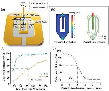
FIG.2.FEA simulation results for the VI with SiO2 particles. (a) Schematic diagram of the VI.(b)Velocity distribution of air flow and particle trajectories of PS2 and PS5 in the VI.(c)Measured particle collection efficiency in the major flow vs Q.(d)Fitted curve showing that the 50%cutoff diameter is 2 μm.
From Eq.(2),we deriveCc=1.066528,and we then substituteCcand the parameters from Table I into Eq. (1). A total flow rateQin the range 67.0-82.5 ml/min is calculated forSt50in the range 0.479-0.590.
A finite element analysis(FEA)is performed to explore the air flow state in the VI,with the particle tracing module and the laminar flow module in COMSOL Multiphysics 5.0 software being used for a multiphysics simulation. The VI inlet is designed with widthD1× thicknessTof 500μm × 500μm. The widthSof the major channel is determined byS/D1=1.4,and the widthD2of the minor channel byD2/D1=1.5.The Reynolds numberRerepresents the flow state condition,which is another important parameter of the VI.The flow in the VI is laminar forRe<2000 and turbulent forRe>4000.29The Reynolds number is dimensionless in any consistent system of units and is calculated as

whereρis the density of air,Uis the average flow velocity through the acceleration nozzle, andμis the viscosity of air. According to the calculation,Reranges from approximately 46.7 to 367.5,which proves that the air flow is steady and laminar.

TABLE I.Simulation parameters of the VI.
Silicon dioxide(SiO2)particles of diameters 2 μm and 5 μm are used in the theoretical computation and the simulation. These are denoted by PS2and PS5,respectively.Figure 2 shows the simulation results.
Figure 2(b) shows the velocity distribution of the air flow in the VI.The air flow velocity at the nozzle is greatest when the inlet flow rateQis set as 82.5 ml/min,and it is greater in the major flow channel than in the minor flow channel.The trajectories of SiO2particles in Fig. 2(b) show that the number ratio of PS2in the major and minor flow channels is 1:1 whenQ= 82.5 ml/min. However,the PS5flow mainly to the minor flow channel. Figure 2(c) shows the particle collection efficiency in the minor flow channel.The collection efficiency for PS5reaches a plateau after a sharp increase at the beginning, while the collection efficiency for PS2increases gradually and reaches 50% whenQ= 82.5 ml/min. As shown in Fig.2(d),the fitted curve reveals a 50%cutoff diameter of 2 μm whenQ=82.5 ml/min.
III. EXPERIMENTAL SECTION
A. Materials
SiO2particles of diameters 2 μm,5 μm,and 10 μm were purchased from Aladdin, Shanghai, China (99.9% purity for all particles).Water-soluble gelatin membrane of thickness 250μm(#17528-80-ACD, Sartorius AG, G?ttingen, Germany) was cut into squares(about 0.8 cm × 0.8 cm) for particle collection. The back-end FET chip was a commercial n-channel MOSFET with 0 V threshold voltage(ALD110800,Advanced Linear Devices,Sunnyvale,CA,USA).The mini vacuum pump was purchased from Skoocom Electronic(SC3101PW,Shenzhen,China).
B. Fabrication of integrated PM separation and deposition module
The VI was fabricated by a micromachining technique with profile dimensions of 40 mm×15 mm×10 mm.The chip consisted of an air inlet A(2 mm in diameter),two air outlets B and C(2 mm in diameter),and one square opening(2 mm×2 mm).The thermal electrode for thermophoresis was fabricated by depositing a 10 nm layer of chromium(Cr)and a 200 nm layer of gold(Au)on a glass layer.The resistance of the electrode was 28 Ω.
The VI and the thermal electrode layer were bonded together by applying epoxy to form the PM separation chip. The electric control system was then prepared by connecting an STM32-based digital actuator controlling system with a human-machine interface (HMI) touch screen. Finally, the PM separation device was integrated by assembling the PM separation chip, the electric control system, the mini pump, and gas pipes together [see Fig. 5(a)below].
C. Fabrication of the FET detection module
The off-chip EGFET consists of two main parts: a frontend extended-gate chip and a back-end FET chip. The front-end extended-gate electrode (17 Ω) layer was fabricated by depositing a 20 nm Cr layer and a 100 nm Au layer on a glass substrate. The positively charged surface of the electrode layer was prepared by immersing this layer into a poly-L-lysine hydrobromide(PLL)solution for 20 min.A polydimethylsiloxane(PDMS)access hole(8 mm in diameter)was then bonded onto the electrode layer to form the particle detection chamber. The extended-gate electrode was then wire-bonded into a ceramic chip carrier. The final FET detection module was fabricated by inserting the front-end extended-gate chip into a back-end FET chip(ALD110800,Advanced Linear Devices)in a homemade integrated circuit.
D. Particle generation and separation
The particle collection efficiency experiments on the VI were performed independently (see Fig. S1 in the supplementary material).A mixture of PS2and PS5(in a 1:1 mass ratio)was filled into the aerosol generator (RBG 1000, Palas). An aerosol particle flow was then generated and introduced into the mixer with dry and clean air.After mixing,the aerosol particles were diluted by clean air.Then,by adjusting the VI inlet gas flow rate and the suction power of the vacuum pump, the aerosol particles flowed into the VI with an appropriate flow rate, and the PS2and PS5could be separated accurately.An optical particle counter(SOLAIR 1110,Lighthouse)with 10 size bins was used to count the particles at the VI inlet,minor flow outlet, and major flow outlet, respectively. During the operation, the minor-to-major flow ratio was fixed at 1:9, and the inlet air flow rateQwas controlled to increase from 65 ml/min to 105 ml/min.
E. FET measurements
After presetting of the inlet flow rate (85 ml/min) and the collection time (30 s) through the HMI screen, the SiO2particles were subsequently collected on a gelatin membrane through thermal deposition in the major channel. A particle solution was then prepared by dissolving the membrane in 500μl deionized water,and this solution was added to the reservoir of the FET detection module for analysis. The characteristics of the FET were confirmed offline using source measure units(Keithley 2636 and 2400 SMUs)to establish the correct operating point before the real-time measurements.During all the measurements,the Ag/AgCl reference electrode was held at a constant potential of 0 V, while the bias voltage of the FET was set to 0.3 V to ensure that it was working in the linear amplification range.
IV. RESULTS AND DISCUSSION
A. Particle separation
Figure 3 shows the results for the collection efficiency for SiO2particles by the VI.As can be seen in Figs.3(a)and 3(b),both PS2and PS5gradually move from the major flow channel C to the minor flow channel B.However,PS5changes more rapidly than PS2.Figure 3(a)shows that when the initial inlet flow rate is low (Q= 65 ml/min),the collection efficiency for PSC2(PS2in the C outlet)is higher than that for PS B2 (PS2in the B outlet). With increasing inlet flow rateQ, the collection efficiency for PSB2gradually increases and intersects with the collection efficiency for PSC2whenQ= 85 ml/min.At this intersection point, the collection efficiency for PS2in both flows is almost equal to 33%, which is taken to be the realization of a 50% cutoff diameter of 2 μm atQ= 85 ml/min. The collection efficiencies for PS5in the two different flows are 46.66% and 4.67%, respectively, whenQ= 85 ml/min [Fig. 3(b)]. This is a further indication that the coarse particles(PS5)with greater inertia are more willing to follow their primary directions than the fine particles(PS2).In addition,the calculated particle loss in the VI is shown in Fig.3(c).It can be seen that the particle loss is minimal whenQ=85 ml/min and is 27.13%for PS2and 25.52%for PS5.The particle loss in the VI is due to deposition during particle motion. The motion of some particles is severely retarded owing to friction with the sidewalls and to air resistance,and so these particles do not have enough energy to reach the optical particle counter and instead are deposited halfway.This particle loss is related primarily to the structure of the VI and the length of the air pipe.The above data analysis shows that the VI has good performance with a 50% cutoff diameter of 2 μm for the SiO2particles when the inlet flow rateQis 85 ml/min.
B. Thermophoresis
After particle separation, the target particles (fine particles)flow into the major flow channel,where the thermal collection area is located. This area consists of a top heater electrode, the rectangular opening of the VI, and a bottom collection layer. When a temperature gradient is established in a gas, an aerosol particle in that gas experiences a force in the direction of decreasing temperature. The particle movement that results from this force is called thermophoresis (see Sec. 2 in the supplementary material).31

FIG.3.(a)and(b)Collection efficiencies for 2 μm and 5 μm SiO2 particles,respectively,with Q ranging from 65 ml/min to 105 ml/min.(c)Particle loss in the VI vs Q.
As shown in Fig.4(a),the temperature of the electrode increases as the result of the applied voltage(0.5-3 V).An FEA simulation was performed to investigate the thermophoretic deposition of particles in a real operating atmosphere. As shown in Fig. 4(b), a plate-toplate thermal precipitation simulation model was established based on the real PM separation device parameters and the actual air flow conditions in the VI. The distance between the top electrode layer and the bottom collection layer was set as 500μm, the resistance of the electrode as 28Ω,and the boundary condition as adsorption mode. During the simulation, the applied voltage of the electrode was controlled to increase from 0.5 V to 3 V, and the relationship between the particle thermal deposition efficiency and this applied voltage is shown in Fig. 4(c). The deposition efficiency curve can be divided into three stages. In the first stage, the particle deposition efficiency increases slowly with increasing voltage,which indicates that the temperature gradient cannot provide sufficient thermal force to push the particles downward quickly enough to prevent most of them from leaving the collection area. As the voltage continues to increase, the curve goes into the second stage,in which the deposition efficiency increases rapidly. In the final stage,the deposition efficiency curve gradually reaches a plateau and remains unchanged despite further increases in voltage. To determine the optimum applied voltage for particle deposition,we took photographs of deposited particles at different applied voltages(see Fig. S2 in the supplementary material) for analysis, and the results are shown in Fig.4(d).It can be seen that 3 V is the optimum applied voltage for particle collection by thermophoresis.
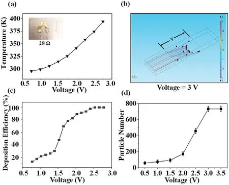
FIG.4.Results of the analysis of the thermal electrode.(a)Temperature rise characteristics of the electrode.(b)Schematic of FEA simulation of particle deposition at 3 V. (c) FEA simulation results for SiO2 particle deposition efficiency at different voltages. (d) SiO2 particle deposition results at different voltages based on photographic analysis.
C. Microsystem integration
After optimization of the particle separation and deposition module, a prototype PM sensing system was developed [Fig. 5(a)].Its principal components are a VI with a top heater, a mini vacuum pump(see Fig.S3 in the supplementary material),an STM32-based digital actuator control system, and an HMI touch screen(see Fig.S4 in the supplementary material).The STM32-based control system [Fig. 5(b)] consists of a data acquisition circuit, an alarm circuit, and a serial communication circuit. The assembled miniature particle separation and deposition system is shown in Fig.5(c).
To quantify the separated particles, the EGFET setup uses a gold extended electrode connected to the gate terminal of a conventional MOSFET [Fig. 5(d)]. The particles in solution are charged,and so, by keeping the gate voltage and the properties of the solution constant,the adsorption of particles onto the gold electrode can function as an extra virtual gate bias, which changes the threshold voltage of the MOSFET.32In principle, the EGFET can be integrated into the particle separation and deposition system as well.The important issue here is the integration of the on-chip reference electrode,since the FET measurement is based on the voltage difference between the gate electrode (after particle adsorption)and the reference electrode. To clarify this issue, we demonstrated the performance of the combined system by deposition of the particles onto a water-soluble gelatin membrane of thickness 250μm. After particle deposition, the gelatin film was transferred and dissolved in a solution chamber, where a regular Ag/AgCl electrode was applied to measure the potential change on the EGFET.
D. Particle sensing results
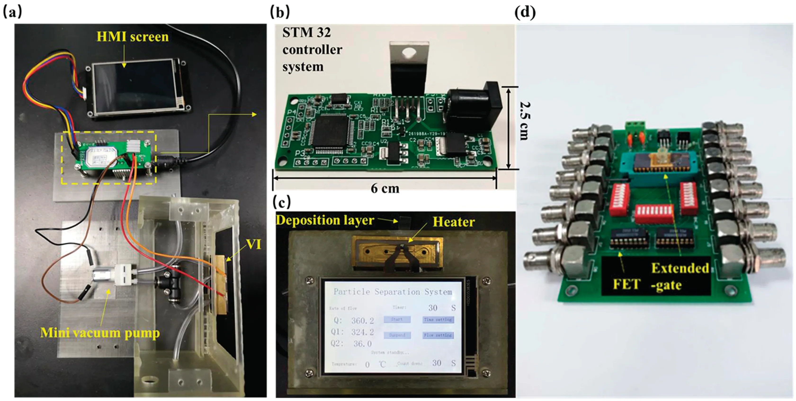
FIG.5.(a)Components of the PM separation device.(b)STM32 controller system.(c)Integrated PM separation device.(d)Integrated PM detection module.
To verify the PM analysis of the combined microsystem, we first investigated the sensing performance of the FET on particle concentrations after collection by the VI. PS2was selected as the analyte in this experiment. Aerosol particles of different sizes generated from the aerosol generator were respectively introduced into the integrated PM separation device.The generation velocities of the aerosol particles ranging from 6 mm/h to 150 mm/h corresponded to concentrations of aerosol particles ranging from low to high.After the inlet flow rate of the VI had been set as 85 ml/min and the collection time as 30 s through the HMI screen, the outlet of the minor channel of the VI was turned off to force all the particles to flow to the major channel. PS2were subsequently collected on a gelatin membrane through thermal deposition in the major channel. A particle solution was then prepared by dissolving the membrane in 500 μl deionized water, and this solution was added to the integrated PM detection system.As shown in Fig.6(a),after the introduction of the collected PS2into the liquid chamber, the current value of the FET increased rapidly to a plateau.Figure 6(b)shows the linear relationship between the current change ΔI of the FET and the generation velocity of the aerosol particles.The results suggest that quantitative information about particle concentration can be obtained directly with the FET module based on absolute measurements.
Under the same experimental conditions,we used PS2,PS5,and PS10to investigate the effect of particle size.Three types of particles were respectively generated with the maximum generation velocity(150 mm/h). Figure 6(c) shows the real-time responses of the FET to PS2,PS5,and PS10.After PS2,PS5,and PS10had been introduced independently into the liquid chamber,the values of the FET current for all three particle sizes increased rapidly to a plateau. The inset in Fig.6(c)shows a comparison of ΔI of the FET among the three sizes of particles,and it can be seen that the adsorption of larger particles results in a smaller change in the interfacial potential of the extended gate electrode.This can be explained by the Debye screening effect of the FET. This screening effect is enhanced exponentially with distance from the charged particles to the surface of the extended gate electrode and is quantified by the Debye length.In the case of adsorption of SiO2particles,the particles are actually larger than the Debye length, and thus smaller particles lead to greater surface charge densities within the Debye length and induce greater changes in the interfacial potential of the extended gate electrode[Fig.6(d)].

FIG.6.(a)Plot of real-time responses of FET to PS2 at different generation velocities.(b)Linear fit of responses of FET to particle generation velocity.(c)Plot of real-time responses of FET to PS2,PS5,and PS10,the inset summarizes the current changes of FET in response to PS2, PS5, and PS10. (d) Schematic of the Debye screening effect on larger and smaller particles.
Next,experiments using mixtures of particles of different sizes were performed to simultaneously demonstrate the particle separation and detection performance of the combined PM sensing system.Mixed SiO2particles(a mixture of PS2and PS5in a 1:1 mass ratio and a mixture of PS2, PS5, and PS10in a 1:1:1 mass ratio) were generated by the aerosol particle generator with a maximum generation velocity of 150 mm/h. In this experiment, we turned on the outlet of the minor channel and set the inlet flow rate of VI as 85 ml/min and the collection time as 30 s. The mixed aerosol particles flowed into the integrated PM separation device and were separated instantly in the VI. Subsequently, the separated particles were collected through thermal deposition and transferred to the FET measurement setup as described above.Figure 7(a)shows the detection results for mixed particles. The black line represents the detection results for PS2,with a ΔIresponse of 6.78 μA.The orange line represents the detection results for mixed PS2and PS5,for which ΔIwas about 4.47 μA.The gray line represents the detection results for mixed PS2,PS5and PS10,withΔIof about 2.63 μA.A comparison of the ΔIvalues is plotted in Fig. 7(b). Compared with pure PS2,the ΔIof mixed PS2and PS5dropped by about 34%,indicating that the mixed particles had been successfully separated by the VI.It can be inferred that under the cutoff flow rate of 85 ml/min,nearly 100% of the PS2and a small number of the PS5were distributed to the major flow channel. Moreover, most of the larger particles(PS5) were forced to flow into the minor flow channel. The 61%decrease in the ΔIof PS2,PS5,and PS10provides further confirmation of the separation performance of the integrated PM separation device.
From the above experimental results,we can conclude that the FET device is appropriate for particle analysis with stable detection performance.Compared with light scattering methods,the proposed system has the potential to provide more accurate and long-term calibration-free measurements based on a combination of front-end PM separation and back-end PM detection.Different-sized particles can be initially differentiated by the VI without the need for subsequent calibration. In addition, the FET can differentiate differentsized particles,which means that the VI can provide the first level,namely,separation,and the FET the second level,namely,detection,which will give more precise results.
Regarding the maintenance of the system,the top heater electrode and the VI channel can be cleaned by air blowing after each measurement.For the FET detector,since the particles are physically adsorbed onto the electrode, the deposited particles can be simply rinsed off with water, thus allowing the electrode to be reused. All cleaning processes are easy to perform,without the need for extensive training of the operator,and potentially can be automated.We tested our system for three to four months, with cleaning being carried out regularly. For long-term operations, since the PM separation device can be disassembled into the top heater electrode and the VI, both of these can be replaced if heavily clogged.Because of the physical separation of the gold sensing electrode from the MOSFET,the sensing electrode of the off-chip EGFET can also be replaced, with the FET device itself being reused. Because the VI, deposition electrode, and FET sensing electrode can be mass-produced,this significantly reduces the cost of the sensor.
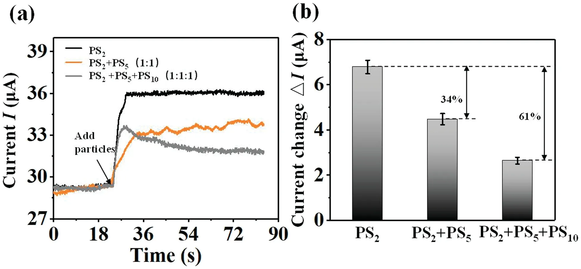
FIG.7.(a)Real-time responses of FET to PS2 and two mixtures of particles.(b)Bar graph of ΔI of FET for PS2 and two mixtures of particles.
V. CONCLUSIONS
A combined PM analysis microsystem consisting of a PM separation device based on a VI and a PM detection module based on an FET has been described here.In contrast to methods based on gravimetric analysis or light scattering,this approach allows the analysis of PM in terms of absolute numbers and size distributions without the need for calibration. An FEA simulation and experimental results have verified that the PM separation device can operate with low air flow rates for PM separation.The FET detection module is used to quickly monitor the particles based on the electric charges that they carry. The experimental results prove that this module is able to measure particles with different concentrations and sizes in real time and in a label-free manner.As a demonstration with realistic PM,we have applied this system to analyze mixtures of particles,and the results have confirmed the ability of our device to perform on-site PM analysis quickly and accurately. Owing to its advantages of compact structure,low cost,simple fabrication,and ease of operation,the proposed microsystem has great potential for various point-of-need applications and can be used in heavily polluted and industrial environments.
SUPPLEMENTARY MATERIAL
See the supplementary material for the particles separation setup, the mechanism of particle thermophoresis, photographs of deposited particles, electrical control of the inlet air flowrate, and a detailed description of the STM32-based control system.
ACKNOWLEDGMENTS
This work was supported by the National Natural Science Foundation of China(Nos.91743110,61674114,and 21861132001),the National Key R&D Program of China (Nos. 2017YFF0204604 and 2018YFE0118700), Tianjin Applied Basic Research and Advanced Technology(No.17JCJQJC43600),the“111”Project(No.B07014), and the Foundation for Talent Scientists of Nanchang Institute for Micro-technology of Tianjin University.
- 納米技術與精密工程的其它文章
- Propagation characteristics of photonic crystal fibers selectively filled with ionic liquid
- Deep-learning-based nanowire detection in AFM images for automated nanomanipulation
- Design of a hexagonal air-coupled capacitive micromachined ultrasonic transducer for air parametric array
- On-site low-power sensing nodes for distributed monitoring of heavy metal ions in water
- Characteristics of Ni-based ohmic contacts on n-type 4H-SiC using different annealing methods

