Lorentz transmission electron microscopy for magnetic skyrmions imaging?
Jin Tang(湯進(jìn)), Lingyao Kong(孔令堯), Weiwei Wang(王偉偉),Haifeng Du(杜海峰),3, and Mingliang Tian(田明亮),
1High Magnetic Field Laboratory,Chinese Academy of Sciences(CAS),Hefei 230031,China
2School of Physics and Materials Science,Anhui University,Hefei 230601,China
3Institutes of Physical Science and Information Technology,Anhui University,Hefei 230601,China
Keywords: magnetic skyrmion,Lorentz transmission microscope,nanostructures
1. Introduction
Magnetic skyrmions are vortex-like spin textures with nontrivial topology. In the 1960s,they were proposed by Tony Skyrme as quantized topological defects in a continuous field to account for the stability of hadrons in particle physics.[1]A similar magnetic skyrmion structure was theoretically predicted in the 1980s by Bogdanov and Yablonskii when investigating magnetic vortices in magnetically ordered crystals lacking inversion symmetry.[2]By using neutron scattering in chiral MnSi,skyrmions were experimentally observed in 2009.[3]Since then,interesting properties have been reported for these quasiparticles.The size of a single skyrmion is typically on the order of 3 nm to 100 nm,depending on the material parameters and external fields.[4,5]Also,they can be manipulated by various external stimuli, such as electric current in metals, electric fields in insulators,strain,and heat current.[6]Notably,the threshold current density required to move skyrmions, which is approximately three to five orders magnitude smaller than that required for the drive of a ferromagnetic domain wall,is reported to be extremely low in noncentrosymmetric bulk crystals.[7]Magnetic skyrmions have several advantageous properties,including controllable nanometer size,low threshold current required for motion,and topological stability.Such characteristics are necessary for next-generation,low-energyconsumption,and high-density memory or logic devices.
According to the chiral state of a magnetic structure,there are two main kinds of magnetic skyrmions: Bloch-type and N′eel-type, Fig. 1. The former has been widely reported in B20-type alloys with noncentrosymmetric materials, including MnSi,[8]Fe1-xCoxSi,[9]CoZnMn,[10]Cu2OSeO3,[6]and FeGe.[11]The antisymmetric Dzyaloshinskii-Moriya (DM)interaction,stemming from the spin-orbit interaction in these noncentrosymmetric lattice structures,is important in the stabilization of magnetic skyrmions. N′ee-type skyrmions are generally induced by the interfacial DM interaction and have been studied in ferromagnetic heavy metal heterostructures,such as Fe/Ir[12]and Co/Pt.[13]Recently, a room-temperature magnetic skyrmion bubble was observed in the frustrated Kagom′e lattice structure of Fe3Sn2. This originated from the competition between magnetic dipole interaction and uniaxial magnetic anisotropies.

Fig.1.(a)Bloch-type magnetic skyrmion:the magnetic moments rotate in the tangential planes from the core to the periphery. (b) N′eel-type magnetic skyrmion: the magnetic moments rotate in the radial planes from the core to the periphery.
In addition to neutron scattering,which was used to identify magnetic skyrmions for the first time,[3,14]various exper-imental techniques have been employed to investigate their physical properties. These include magneto-transport (i.e.,magneto-resistance),[15]spin-polarized scanning tunneling microscopy,[12]magneto-optical Kerr effect microscopy,[16,17]magnetic force microscopy,[13,18]and full-field magnetic transmission soft x-ray microscopy.[19]Among these,Lorentz transmission electron microscopy(Lorentz-TEM)is regarded as the most efficient method because of its ultrahigh magnetic spatial resolution (down to 2 nm).[7,10,11,20-24]In fact,the fine magnetic structure of a skyrmion was first observed in real-space using Lorentz-TEM,where the magnetic skyrmion showed an enhanced stability over a wide temperature-field region in thin plates.[25]
Recently,many theoretical studies have demonstrated the possibility of hosting and manipulating individual skyrmions in magnetic nanostructures.[22,26]These novel phenomena emerging in confined geometries should be helpful to develop skyrmion-based spintronic devices.[27]However, direct realspace imaging of magnetic skyrmions in nanostructures remains challenging for two reasons. First, using the Lorentz-TEM method,an artificial magnetic contrast exists around the edge because of strong Fresnel fringes induced by the sharp interface between the sample and vacuum. Therefore, the magnetic resolution in a nanostructure geometry is strongly reduced,especially around the edge. Second,obtaining magnetic nanostructures with the desired geometries is difficult because high-quality helimagnetic films must be fabricated.Recently,well-defined geometries were successfully obtained via a top-down method using a focused ion beam and scanning electron microscope(SEM)dual-beam system.[26]In addition,coating the nanostructure with a metallic layer has been found to significantly reduce the Fresnel effect at the edge.[22,28]These developments allow to investigate the magnetic helix and skyrmion states in magnetic nanostructures using realspace Lorentz microscopy. In this work, we first describe the Lorentz-TEM technique, also including Lorentzelectron holography(EH),and then we review recent developments in the observation of magnetic skyrmions using Lorentz-TEM.
2. Lorentz-TEM
Lorentz-TEM has been extensively used for many years to study magnetic domain structures and magnetization reversal mechanisms of magnetic thin films. In this technique,the objective lens is always switched off to ensure that the magnetic sample is not influenced by the high magnetic field localized at the pole pieces(~2 T).When using Lorentz-TEM for magnetic imaging, the typical achievable resolution is 2 nm.Several modes can be used to obtain qualitative and quantitative information from magnetic domain structures. Another advantage of this methodology is that in situ magnetic fields or other external stimuli can be applied, enabling realtime recording of the local dynamic magnetic behavior of the sample.[29]
In this work, we first introduce the principle of Lorentz microscopy.Then,we review commonly used imaging modes,Fresnel and Foucault. Finally,we describe the transport of intensity equation(TIE)method,which was used to obtain quantitative magnetic information.
2.1. Basic principles

In TEM, a high-energy (100 keV-1000 keV) electron beam is transmitted through a thin specimen. When the beam passes through a region of magnetic induction in the sample,the electrons are deflected by the Lorentz force, as shown in Fig.2. The Lorentz force is expressed as follows:where e and v are the charge and velocity of the electrons,respectively, c is the velocity of light in vacuum, and B is the magnetic induction averaged along the electron trajectory.Note that only the components of magnetic induction normal to the electron beam (in-plane magnetic components) lead to a deflection. Stray fields above and below the specimen also contribute to the image. The direction of the force obeys the left-hand rules, and the deflection direction depends on the magnetization direction within the domain.
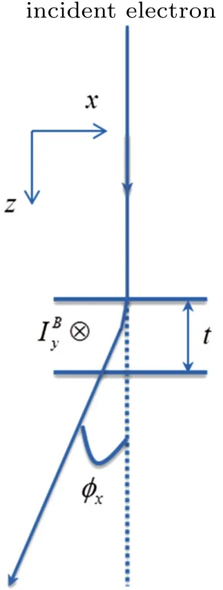
Fig.2.Scheme showing the deflection of fast electrons by Lorentz force after passing through the magnetic sample.
The Lorentz deflection angle φxalong the x direction is given by[30]

where t is the specimen thickness, m the electron mass, and IBythe magnetization along the y axis. The deflection angle is proportional to the product of the averaged magnetic induction and specimen thickness. A high accelerating voltage would lead to a small deflection angle, which is suitable for samples with large thickness. By substituting typical values into Eq.(2),the deflection angle rarely exceeds 100μrad,which is much smaller than Bragg scattering that has a typical value of~10 mrad. The deflection of the incident electron beam by Lorentz force results in an image contrast under certain experimental conditions,providing useful magnetic information.
2.2. Imaging mode of Lorentz-TEM
Lorentz-TEM allows to dynamically record the changes in magnetic microstructures in either the absence or presence of an applied magnetic field. The image contrast results from the in-plane component of magnetization in the specimen,yielding bright or dark intensity bands at the position of magnetic domain walls. The Fresnel and Foucault imaging modes are the most commonly used. Figure 3 illustrates the mechanism of magnetic contrast for a simple specimen containing domains in the plane of the film separated by 180°domain walls.[31]The Lorentz force deflects the electrons passing through the specimen and splits each of the diffraction spots into two in the back focal plane of the objective lens.Each split spot contains information about the magnetic induction from the domains in which magnetization is found.
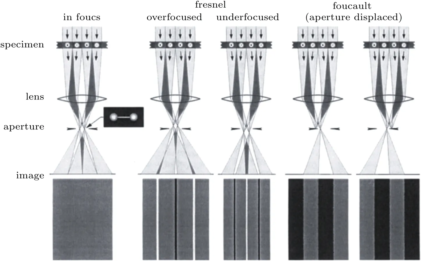
Fig.3. Scheme representing the origin of the Lorentz deflection in Lorentz-TEM for a magnetic film containing 180° domains magnetized in two directions. Fresnel images were obtained by over-or under-focusing the objective lens. Foucault images were obtained by displacing the objective aperture to choose the split diffraction spots by domains with different magnetization direction.[31]
2.2.1. Fresnel mode
In the Fresnel mode, the Lorentz lens is defocused so that an out-of-focus image of the specimen is created. As shown in Fig. 3, for the middle domain wall in the overfocused conditions, the electron deflection induces a lowintensity contrast because electrons are deflected away from the domain wall. This results in a dark contrast line in the domain wall region.[31]Similarly,a bright contrast line is observed in under-focused conditions because of the increased electron density caused by overlapping. The magnetic domain walls are thus visible as alternating bright and dark lines. The domain wall contrast can be changed from dark to bright,and vice versa,by changing the sign of the defocus.
It is worth noting that this mode allows to see only the domain walls but not the domains. Some advantages of using the Fresnel mode to study magnetic specimens are the ease of operation and high contrast. It is easy to perform real-time in situ imaging,allowing reversal sequences to be recorded. The Fresnel mode,however,always works at the defocused conditions and the strong Fresnel fringes are seen where the abrupt change of projection potential occurs,thus blurring the effective magnetic contrast. Therefore, the Fresnel mode was not suitable to study the magnetic state at the edge of the sample in that study.
2.2.2. Foucault mode
In the Foucault mode, the Lorentz lens is in focus, and split spots appear in the diffraction pattern. By displacing the aperture in the back focal plane to select the specific spots,the contrast resulting from the corresponding magnetic domain is formed, similar to the diffraction contrast. The domains in which electrons are deflected through the aperture are bright, whereas domains with magnetization antiparallel to that of the bright domains are dark(Fig.3). When there are several domains in the illuminated area, as seen in Fig. 4(b),the electron beam deviates in different ways according to the different domains.[32]This results in a split diffraction spot,Fig.4(a).[32]From this experiment,it can be immediately determined whether the direction of magnetization is normal to the direction of spot splitting.
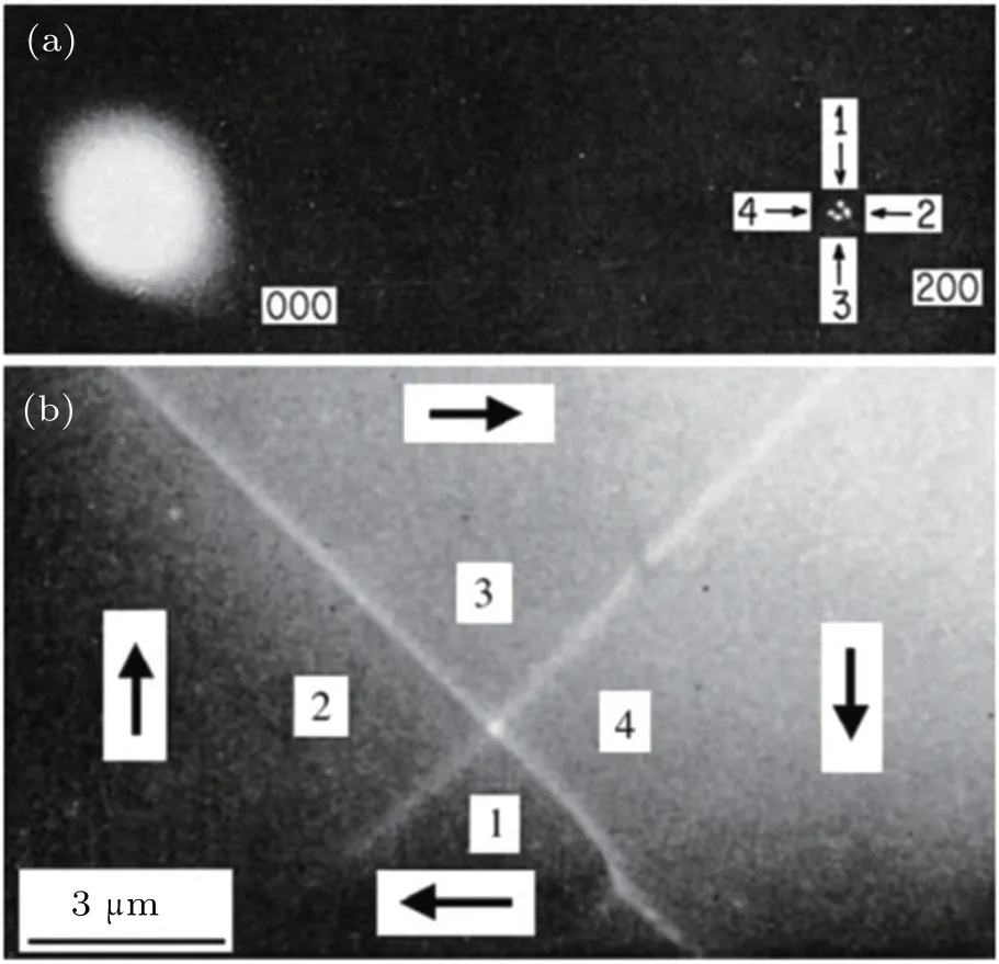
Fig.4. (a)Splitting of 200 spots from a Ni3Mn sample caused by the presence of magnetic domains.(b)Image from all of the split spots in(a)showing the four domains that scattered electrons into various spots.[32]
The contrast in Foucault images is sensitive to the position of the aperture. Therefore, the technique is not quantitative if only a single pair of Foucault images is recorded along each aperture. In addition,as mentioned above,the deflection angle is very small compared to Bragg scattering. The position of the aperture has to be carefully set in the experiments to distinguish each split spot.
2.3. TIE
Images of magnetic domain walls can be obtained via the Fresnel mode of Lorentz-TEM. More recently, the TIE method[33]was developed to allow Fresnel images to quantitatively reconstruct the phase associated with magnetic thin films,[34,35]thus obtaining further magnetic information.
Mathematically, the TIE corresponds exactly to the Schr?dinger equation for high-energy electrons in vacuum under the small-angle approximation. The TIE formula can be written as follows:[36]

where I(xyz)and φ(xyz)represent the intensity and phase distributions,respectively,?I/?z is the intensity derivative along the wave propagation direction,and ?xyis a two-dimensional Laplace operator.
This equation relates the phase distribution with the intensity distribution and its derivative with respect to the direction of wave propagation. Note that TIE does not assume any scattering model, and thus can be used TIE even for strong phase objects. Since the small-angle approximation for the Schr?dinger equation is the basis for microscopy techniques that use high-energy electrons,TIE may be universally applied in electron microscopy.
Because TIE is a partial differential equation,a practical way to solve it was devised.[36]The final expression for the numerical solution is

One of the difficulties of using TIE is to estimate the intensity derivative with respect to z as accurately as possible. The intensity derivative is a mathematical concept, and in practice, a finite difference is calculated to approximate it.Figure 5 schematically shows an experimental situation for the application of the TIE, in which the image intensities were measured at a few consecutive planes. Image processing was performed in the QPT software for Digital Micrograph.[37]
Conversely, according to the Maxwell-Amp′ere equations, in a magnetic field, φ (xyz) and the magnetization M have the following relationship[24]

where t is the thickness of the thin-plate sample,and n is the unit vector parallel to the beam direction.

Fig. 5. Estimation of the intensity derivative along the direction of wave propagation.[36]
3. Off-axis EH
Off-axis EH is based onthe formation of an interference pattern or hologram in TEM.In conventional TEM techniques,only the spatial distribution of image intensity can be recorded.In contrast, in EH the phase shift of the high-energy electron wave that passed through a specimen can be directly measured.Because the phase shift is sensitive to local variations in magnetic and electrostatic potentials, this technique can be used to obtain quantitative information about magnetic and electric fields in materials and devices with a spatial resolution that can reach the nanometer scale.
In the following sections, we briefly introduce the basic setup for off-axis EH.Then, we describe the principle of offaxis EH and the extracting phase from an experimental hologram. Finally, we discuss the application of off-axis EH to a local magnetic measurement.
3.1. Basic setup
Off-axis EH examines electron-transparent samples using defocused illumination from a highly coherent field-emission gun electron source. The region of interest should be positioned as shown in Fig. 6, so that approximately half the field of view is covered. Applying a voltage to an electron biprism results in the overlap of a reference electron wave that passes through the vacuum with one that passes through the sample (Fig. 6). The amplitude and phase shift of the wave are respectively recorded in the intensity and position of the hologram. Changes in the position or spacing of the interference fringes corresponds the relative phase shift of the electron wave that passes through different sections of the sample.When studying magnetic materials, a Lorentz lens allows to operate the microscope at high magnification with the objective lens switched off and the sample in magnetic-field-free conditions,Fig.6(b).

Fig. 6. Scheme of microscope geometry for off-axis electron holography: (a)electrostatic phase shifts corresponds the projected potential times the sample thickness, (b) slope of phase shift corresponds to the sample magnetization.[38]
3.2. Basic principles
An expression for the intensity distribution in an off-axis electron hologram can be obtained by considering the addition of a plane reference wave to a complex specimen wave as follows:[39]where r is a two-dimensional vector in the plane of the sample.The electron wave function of an object in the image plane is given by the following expression:


where A and φ refer to amplitude and phase,respectively. By combining these two expressions, equation(6)can be rewritten as

Three separate contributions are considered for the intensity distribution in the hologram:both the reference and specimen image intensity,and a set of cosinusoidal fringes. The local phase shifts and amplitudes are equivalent to the phase and amplitude of the electron wavefunction in the image plane. To extract phase and amplitude information, a Fourier transform is performed for the hologram as follows:[39]

Equation (9) describes a peak centered at the origin corresponding to the Fourier transform of a conventional brightfield TEM image of the sample,and two sidebands centered at q=qcand q=-qccorresponding to the Fourier transform of the desired image wavefunction. To recover the complex electron wavefunction of the object, one of the two sidebands in the Fourier transform is selected, and then the amplitude and phase are extracted through the inverse Fourier transform.
3.3. Extraction of phase shift
Figure 7 illustrates how a phase shift is extracted using off-axis EH. The original recorded hologram is presented in Fig. 7(a), an enlargement showing the bending of the holographic interference fringes at the edge of the sample can be seen in Fig. 7(b). Next, the Fast-Fourier transform (FFT) of the hologram is calculated, Fig. 7(c), yielding a central peak and two sidebands that are complex conjugates of each other.These sidebands contain the phase and amplitude information about the sample that cannot be recovered from the central autocorrelation peak. Then, the inverse FFT is calculated selecting only one of the sidebands, in Fig. 7(c). Finally, the reconstructed complex image is obtained, Fig.7(d). A colorcoded phase image showing details of the magnetic induction is presented in Fig.7(e).
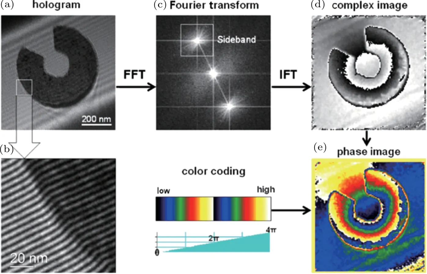
Fig. 7. Overview of the steps for quantitative phase imaging using off-axis electron holography: (a) original hologram, (b) enlargement showing bending of interference fringes,(c)FFT of hologram,(d)reconstructed complex image calculated by inverse Fourier transform from FFT sideband,(e)color-coded phase image showing magnetic induction.[38]
3.4. Application of off-axis EH
The recorded phase can be used to measure the electrostatic potential and the in-plane component of the magnetic induction in the sample. Neglecting the effects of dynamical diffraction,the phase can be expressed as follows:[40]

where

z is the electron beam direction,x is the direction in the plane of the sample,B is the component of the magnetic induction perpendicular to both x and z,V is the electrostatic potential,λ is the relativistic electron wavelength,and E and E0are,respectively, the kinetic and rest mass energies of the incident electron. If neither V nor B varies along the electron beam direction within a sample of thickness t,then equation(10)can be simplified as follows:[40]

The phase gradient can then be interpreted directly and quantitatively in terms of the in-plane magnetic induction. Figure 6 illustrates the imaging of phase shifts and gradients for electrostatic and magnetic fields, respectively. In most cases, the contribution from both electrostatic potential and magnetic induction are involved in the extracted phase. Therefore, they should be separated to separately explore the electric and magnetic properties.
4. Magnetic skyrmions
Magnetic skyrmions were first discovered in the B20 MnSi metallic alloy by using neutron scattering in 2009.[3]Their spin texture was inferred from theoretical calculations.Because the spin arrangement of a magnetic skyrmion is complex and its size is less than 100 nm, it was not easy to obtain an image the fine magnetic configurations. In this sense,Lorentz-TEM could be a useful technique because of its high magnetic resolution (2 nm). A year after the discovery of magnetic skyrmions, a team led by Tokura directly observed vortex-like magnetic configurations in other B20 compounds,Fe0.5Co0.5Si, with high accuracy using Lorentz-TEM.[3]In fact, they had observed a helical ground state in the same Fe0.5Co0.5Si material in 2006.[41]Later, EH was used to observe the magnetic flux in Fe0.5Co0.5Si, where the homogeneous three-dimensional structure of skyrmion lattices was identified.[30]Because of the high magnetic spatial resolution of Lorentz microscopy and EH,these methods have been widely utilized for magnetic microstructures imaging and have also been applied in the in situ magnetization process in the skyrmion research field.
4.1. Fabrication of magnetic nanostructures
Nanostructures from bulk chiral magnets have been fabricated using focus ion beam (FIB) lithography. The surface atoms of the materials acquire high energy from the irradiated heavy metal ions(e.g.,Ga3+and Xe3+)and can thus escape from the mother material. Because the ion beam was focused, the minimum linewidth irradiated could in the nm range, enabling us to fabricate high-precision nanostructures.Furthermore,when irradiating the materials in a metal organic atmosphere, metal organics could be deposited in the irradi-ation zone after decomposition. Using the SEM-FIB dualbeam system, we were able to fabricate nanostructures with various shapes, Fig. 8. The nanostructures were then transferred into copper chipsusing a micromanipulator. They were then thinned onto plates less than 150-nm thick for the TEM measurements.[11,22,42]
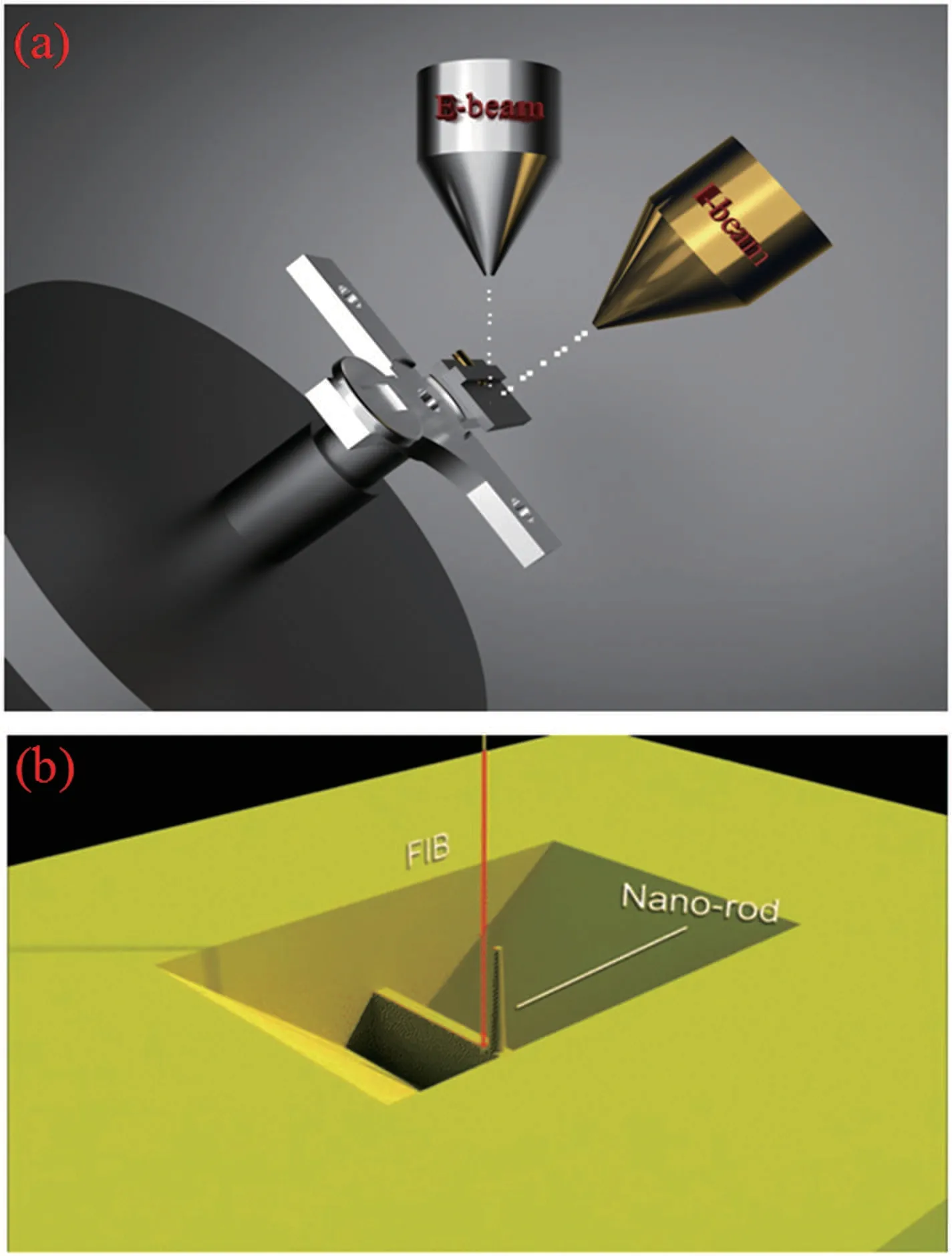
Fig. 8. (a) Schematic diagram of dual-beam microscopy combined with electron and ion optics. (b)In a typical sample fabrication process,a cylinder is obtained by rotating and tilting the sample stage. This system allows for sub-nanometer SEM imaging and also to produce nanostructures with specific geometries with precise prototyping capabilities.
4.2. Observation of skyrmions using Lorentz-TEM
Lorentz-TEM is an important technique to analyze magnetic structures with a resolution of ~2 nm. Skyrmions have been widely investigated using Lorentz-TEM, revealing several unique features.[7,10,24]A typical procedure to obtain the magnetic configurations is shown in Fig. 9. In particular, we stabilized the skyrmion phase in an extended temperature-field region in thin plates that was larger than the corresponding bulk material, in bulk material the region hosting skyrmion phase was only in a tiny temperature-field region close to the critical temperature. The magnetic anisotropy or spatial confinement effect is suggested to be responsible to the stabilization of skyrmions.[43-45]
Observing the skyrmion phase in a small sample in the scale of a single skyrmion size is very attractive because it is directly related to the size of a real device. The Fresnel fringes obtained at under- or over-focus conditions, however,hampered the determination of magnetic structures at the edge of the nanostructure.[11,22]A large Fresnel fringes region was obtained for a larger defocus distance. It was essential to increase the defocus distance to observe the magnetic structure with weak in-plane moments,which in turn enlarged the Fresnel fringes. Note that the Fresnel fringes in the nanostructures with metallic organic Pt-C interfaces could be greatly reduced compared to those with a vacuum interface,enabling the magnetic imaging of a nanostructure with a size down to ~150 nm for a typical skyrmion host material (i.e., FeGe).[10,21]For a more accurate determination of the magnetic structure in samples under 150 nm,EH is preferable because it performed under in-focus conditions.
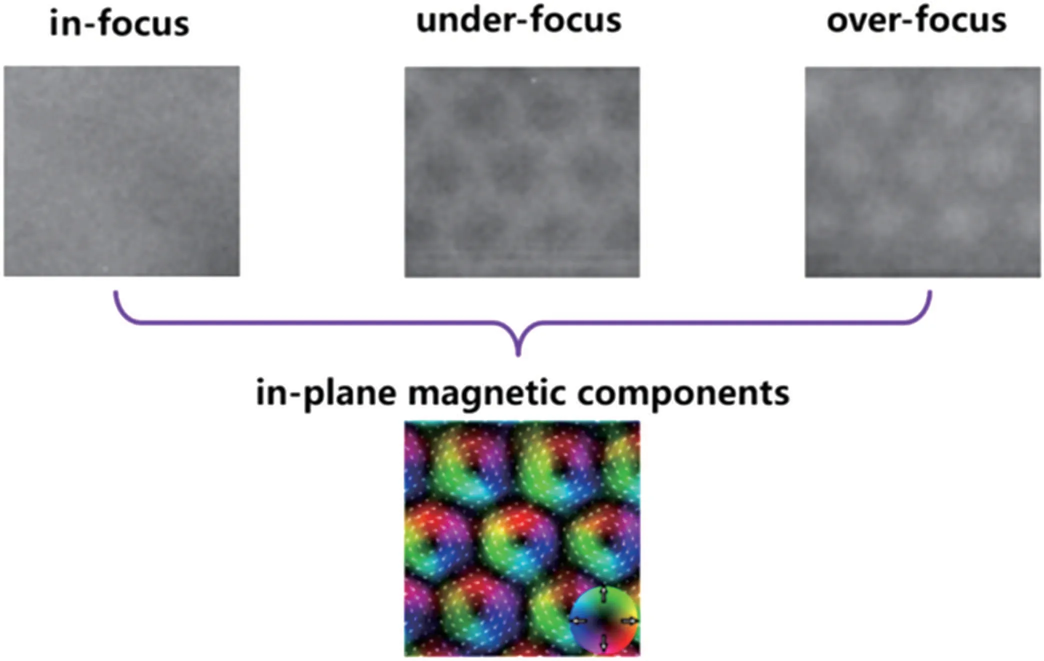
Fig.9. Schematic diagram of the in-plane magnetic configurations obtained for the skyrmion phase. Using Lorentz-TEM,three images were acquired in the same region under three different defocus conditions. The in-plane magnetization distribution map was generated from the phase image by applying Eqs.(3)-(5)(Subsection 2.3). The color wheel represents the magnetization direction at every point.

Fig.10.Size dependence of the skyrmions arrangements of the FeGe nanostrip in panel(a)and nanodisk in panel(b). The measured temperature was 220 K and a magnetic field was applied to stabilize the skyrmion state. W and R represent the width of the nanostrip and the diameter of nanodisk,respectively. The red numbers in panel(a)and panel(b)stand for the number of skyrmion chain and number of isolated skyrmions,respectively.[11,22]
Figure 10 shows the skyrmion arrangements in the helimagnetic FeGe nanostructures.[11,22]Closely packed skyrmions could be observed at high temperature.At low temperatures,one helical stripe was transferred into the skyrmion.The following size effect was demonstrated: for the nanostrips, the number of skyrmion chains decreased as the nanostrip width decreased. It is worth noting that a single chain of skyrmions was observed in the ~130-nm wide FeGe nanostrip, indicating that skyrmion-based racetrack memory could be achieved. Similarly, the size of the nanodisks influenced the whole skyrmion number for the cluster states. In addition to the size effect,we also investigated the temperature and field effects using Lorentz-TEM.For example,skyrmion clusters in nanodisks with different geometrical configurations and fielddriven quantum annihilation of skyrmion numbers have been observed.[11,22]In a FeGe nanodisk at an elevated temperature,close to its Curie temperature,thermal fluctuations enabled the quantum jump between two metastable skyrmion phases with different skyrmion numbers.In a 330-nm FeGe nanodisk,four skyrmions appeared to change their positions with a clockwise or anticlockwise rotation as a result of thermal fluctuations.[11]
4.3. Observation of skyrmions using EH
The EH technique has been widely used to investigate the magnetic flux of magnetic materials. For magnetic skyrmions,the first experiment was performed by Park et al..[30]They used ultrahigh microscopy(1000 kV)with the Lorentz mode,meaning that an external magnetic field could be applied to the sample by exciting the conventional microscope objective lens to a pre-calibrated value. EH enabled the reliable quantification of magnetic states with nanometer spatial resolution and high phase sensitivity. By analyzing the dependence of phase shift on the thickness of thin Fe0.5Co0.5Si plates,Park et al.inferred that skyrmions in plates with a certain thickness were in fact homogenous. In the Lorentz mode,there is a strong Fresnel fringe contrast at the sample’s edge,contrastingly,EH uses in-focus conditions, which are ideal for imaging skyrmions in magnetic nanostructures. In this case, the contribution of phase change arose from (i) an electrostatic phase that originated from local variations in the sample’s thickness and composition, and (ii) a magnetic phase that originated from the magnetic vector potential associated with the sample’s magnetism. To obtain the magnetic phase information, the two phases must be separated, in particular, the area close to the edge of the sample where thickness and composition remarkably change.
We developed an experimental procedure to separate the magnetic contribution to the total phases in a magnetic nanostructure using data from Zheng,[44]Fig.11. The total recorded phase of a FeGe nanodisk at T ~95 K under an applied magnetic field is shown in Fig. 11(c). The spotty contrast in the center of the nanodisk arose from the formation of individual skyrmions. The dominant contrast arising from the electrostatic contribution to the phase, however, hindered the interpretation of the detailed skyrmion structure. To separate the two phases,we recorded the electrostatic phase at T ~300 K,which is above the Curie temperature(TC~280 K)of FeGe.We generated a magnetic induction map from the resulting magnetic contribution to the phase using both phase contour lines of spacing and colors to represent the direction and magnitude of the measured in-plane magnetic induction.
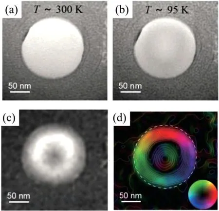
Fig. 11. Experimental procedure to obtain the magnetic flux for a FeGe nanodisk: (a) the sample was analyzed at room temperature to acquire the electrostatic (mean inner potential) contribution because the Curie temperature of FeGe was only 278 K, (b) total phase image (containing both the mean inner potential and magnetic contribution)recorded at T ~95 K,(c),magnetic contribution to the phase obtained by evaluating the difference between the phase images recorded at room temperature and at 95 K,and(d)magnetic induction map of the FeGe nanostrip with a diameter of 160 nm.Data for this procedure are from Zheng.[26]

Fig. 12. Discovery of another localized nanoscale spin texture (i.e., magnetic bobber) in a chiral magnet FeGe nanostrip. (a) Magnetic flux measured in an FeGe nanostrip with a thickness of 175 nm. The circular dots with strong contrast on the right side stand for the skyrmion tubes.The weak dot on the left side corresponds the chiral magnetic bobber.(b)The fine spin configurations for bobber and skyrmions.[46]
Using the EH technique, we achieved an important result, that is, the discovery of a magnetic bobber. Generally,skyrmions are believed to be the only chiral nanoscale spin texture in chiral magnets,[46,47]therefore, pinning a chain of individual sparsely distributed skyrmions to the desired position to achieve data encoding in skyrmion-based memory devices requires a significant effort. In this case,the distance between skyrmions should be quantized to represent the correct number of“0”between“1”. Thus far,however,the approach to maintain such distance between skyrmions was suggested to carve a notch around the edge of the sample. Theoretical work demonstrated that chiral magnets with a certain thickness could stabilize another type of localized excitations,i.e.,chiral bobbers, which may coexist along with skyrmions in a wide range of parameters. As seen in Fig. 12, we accomplished the first direct observation of chiral bobbers using EH.Because the magnetic bobber occupied a significantly smaller volume than that of a skyrmion tube, these two states could be easily distinguished by their net magnetization. Each state would yield a different magnetic contrast in the off-axis EH technique because EH provided a high-spatial resolution and quantitative measurements of the phase shift,which originated from interactions between electrons with an in-plane component of magnetization. The existence of two types of localized and movable objects results in a new magnetic data storage concept, in which the two objects act as the binary state of a data bit.
5. Conclusion
We briefly reviewed the recent developments in Lorentz-TEM and EH and their application in magnetic skyrmions studies. Also, we introduced the basic principles of these two methods and addressed their application for magnetic skyrmion imaging in both thin plates and nanostructures. The Lorentz-TEM method presents important advantages. In future studies,additional results will be obtained using this technique.
- Chinese Physics B的其它文章
- Exploring alkylthiol additives in PBDB-T:ITIC blended active layers for solar cell applications?
- Study on the nitridation of β-Ga2O3 films?
- Thin-film growth behavior of non-planar vanadium oxidephthalocyanine?
- Monolithic semi-polar(1ˉ101)InGaN/GaN near white light-emitting diodes on micro-striped Si(100)substrate?
- Spectral properties of Pr:CNGG crystals grown by micro-pulling-down method?
- Quaternary antiferromagnetic Ba2BiFeS5 with isolated FeS4 tetrahedra

