
An automated approach to calculating the maximum diameters of multiple cutters and their paths for sectional milling of centrifugal impellers on a 4?-axis CNC machine
2019-04-28 05:44:46BohiWUZezhongCHENMingLUODinghuZHANGFeiynHAN
CHINESE JOURNAL OF AERONAUTICS 2019年4期
Bohi WU , Zezhong C. CHEN , Ming LUO , Dinghu ZHANG ,Feiyn HAN
a School of Mechanical Engineering, Northwestern Polytechnical University, Xi’an 710072, China
b Department of Mechanical, Industrial and Aerospace Engineering, Concordia University, Montreal, Quebec H3G 1M 8, Canada
c College of Mechanical Engineering, Xi’an University of Science and Technology, Xi’an 710054, China
KEYWORDS Automated path generation;4?-Axis CNC machining;Centrifugal impeller machining;Cutter diameter optimization;Sectional machining
Abstract Power generators and chemical engineering compressors include heavy and large centrifugal impellers. To produce these impellers in high-speed machining, a 4?-axis milling machine(or a 4-axis machine plus an indexing table)is often used in the industry,which is more rigid than a 5-axis milling machine. Since impeller blades are designed with complex B-spline surfaces and impeller channels spaces vary signif icantly,it is more eff icient to use multiple cutters as large as possible to cut a channel in sections and a blade surface in patches,instead of only using a small cutter to machine a whole blade and a channel.Unfortunately,no approach has been established to automatically calculate the largest diameters of cutters and their paths,which include the indexing table angles. To address this problem, an automated and optimization approach is proposed. Based on the structure of a 4?-axis machine,a geometric model for a cutter gouging/interfering the impeller is formulated,and an optimization model of the cutter diameter in terms of the indexing table angle is established at a cutter contact (CC) point on a blade surface. Then, the diameters of the tools,their orientations,and the indexing table angles are optimized,and each tool’s paths are generated for machining its corresponding impeller section.As a test,an impeller is eff iciently machined with
1. Introduction
Centrifugal impellers are crucial to the performance and life of aero-engines, power generators, and chemical engineering compressors; thus, it is important to machine them with high accuracy and efficiency. In the industry, small centrifugal impellers are often machined on 5-axis CNC machining centers. However, many centrifugal impellers of generators and compressors are large and heavy, whose diameters are several meters and weights are several tons; they are often machined on a 4?-axis milling machine, which is a 4-axis horizontal milling machine plus an indexing table.The reason is that this kind of machine is more rigid and with better kinetics in heavy cuts, compared to a 5-axis machine. Impeller blades are designed with complex free-form (NURBS or B-spline) surfaces,and the channel space between two adjacent blades varies largely. Therefore, several cutters with different diameters should be used: larger cutters for wider channel sections and smaller ones for narrow sections. Cutters should be as large as possible; this is very important for impeller machining with shorter machining time and better blade quality. A current method is that an NC programmer determines several cutters diameters according to their observation and manually plans their paths with CAM software, resulting in smaller cutters and longer machining time. Unfortunately, little research has been conducted on determining largest diameters of multiple cutters and calculating their paths, including the corresponding indexing table angles, for machining centrifugal impellors on this 4?-axis CNC machine. Consequently, the efficiency of machining impellers can be increased. To address this challenge, a comprehensive literature review is conducted below.
Because of the complex shape of centrifugal impeller blades and the small space between two adjacent blades, much research has been conducted, in particular, on automated tool paths generation for 5-axis flank milling of centrifugal impellers. Bohez et al.1built a centrifugal impeller blade model and adopted the flank milling method to cut blade ruled surfaces. Chen and Wang2constructed a centrifugal impeller model with UG II, planned 5-axis tool paths using this software,and simulated machining with Vericut.Tsay et al.3calculated cutter locations in 5-axis milling and tool orientations without collision with a workpiece.Tsay et al.4used ruled surfaces to approximate impeller blades and calculated cutter locations and orientations in 5-axis flank milling. Young et al.5,6proposed a tool path generation method for 5-axis milling of centrifugal impellers. Youn et al.7calculated the range of the tool axis directions without interference at each cutter contact point on marine propeller blades and planned tool paths so that the tool axis was within the range. Chen et al.8modified tool orientations to achieve continuous rotations and eliminate cutting marks on centrifugal impeller blades. Chaves-Jacob et al.9presented an optimal strategy for f inishing impeller blades using 5-axis machining. Fan et al.10proposed a programming method for rough machining of centrifugal impeller blades.Flank milling is an eff icient way of removing raw material,and largest-diameter cutters can further increase machining efficiency.
Since the blade shape is complex,it is difficult to determine the largest diameters of cutters by NC programmers. Several articles on tool size determination are reviewed here.In a study on 4-axis blisk machining,Chen and Liu11formulated a mathematical model of maximizing the cutter size without gouging and interference, and determined the tool size and orientation automatically. Moreover, they12proposed an intelligent approach with multiple cutters of maximum sizes for 3-axis milling of sculptured surface parts.Edalew et al.13set up a procedure for cutting tool selection, and developed a dynamic program-based system that uses mathematical modules and heuristic data to calculate machining parameters and costs.Unfortunately, no research has been conducted on how to automatically determine the largest diameters of cutters and calculate indexing table angles for sectional milling of impellers on a 4?-axis CNC machine.
Flank milling is widely used in rough milling of centrifugal impellers.Thus,articles about the flank(or side)milling theory are reviewed. Bedi et al.14rendered a mathematical model for flank milling with flat end-mills. To locate a cutter tangent to a ruled surface’s directrices and contacting the surface at a point,Senatore et al.15optimized this point and rotation of the cutter about an axis to minimize the deviation between the cutter and the surface.Zhu et al.16represented the swept envelope of a conical cutter as a sphere-swept surface and computed the signed distance between the swept cutter surface and points on the part surface.This method optimizes the conical cutter position for 5-axis flank milling of free-form surfaces.Gong and Wang17proposed a method of generating paths for ball end-mills in 5-axis flank milling of a complex surface, subject to two conditions:(a) the cutter is tangential to specif ied adjacent surfaces, and(b)there is no overcut,and the minimum error is zero.The aforementioned methods can be applied to flank milling of impeller blades,which is not the topic of this article.
A salient feature of 5-axis surface milling is the tool orientation in terms that the part can be changed with two rotational axes, which is subject to the tool not colliding with the part. A great amount of research on f inding an interferencefree tool orientation in 5-axis surface milling has been published.Chiou and Lee18searched for tool orientations without local gouging and global collision based on the swept envelope approach. Ho et al.19applied the quaternion interpolation scheme to generate smooth tool orientations in order to reduce the machining error.Castagnetti et al.20established a range of admissible orientation to represent allowable tool orientations at each cutter contact point. Chen21investigated tool orientations for 5-axis milling of impeller blades. The ideas in these articles are useful to establish an optimization model of cutter diameters without gouging and interference.
However, prior CNC programming methods for 5-axis milling of centrifugal impellers cannot be used to machine impellers on a 4?-axis horizontal CNC machine. This machine has the following features: three translational axes and one rotational axis can be executed simultaneously, and the indexing table can be rotated at discrete angles when the machine is not running. Currently, programmers determine cutter sizes and indexing table angles for machining impellers,which could cause low cutting efficiency and high machining costs. To address this problem, an automated approach of optimizing largest-diameter cutters and their corresponding indexing table angles to cut impeller blades in patches on a 4?-axis machine is proposed. This paper includes four sections. In Section 2, centrifugal impeller machining on a 4?-axis machine is introduced. In Section 3, a mathematical representation for the geometric model of a cutter gouging/interfering an impeller is formulated. In Section 4, an optimization model of the cutter diameter in terms of the indexing table angle is established at a cutter contact (CC) point on a blade surface patch,and a process of optimizing largest cutters and its corresponding indexing table angles is planned to cut a blade surface in patches. Then, in Section 5, a practical example is provided to demonstrate validity and advantages of this approach. Finally, the work is concluded in Section 6.
2. Centrifugal impeller blade machining on a 4?-axis machine
A centrifugal impeller is always composed of two regions, i.e.,the blades and the hub. In most cases, the blades are complex free-form or ruled surfaces,and the hub is a swept surface.It is true in practice that large and heavy centrifugal impellers are machined on a 4?-axis machine (or a 4-axis horizontal CNC machine tool plus an indexing table), instead of on a 5-axis machine. This machine structure is that an indexing table is mounted on the 4-axis machine, and a rotary pallet is mounted on the table (see Fig. 1). The table can be fixed at a number of discrete pre-specif ied angles, [α1,α2,...,αmIT],before machining to attain more space for larger cutters to access the blades,in which mITis the angle number.This table cannot be rotated simultaneously with other axes during machining. Therefore, a complex blade surface can be machined with largest-diameter cutters patch by patch at different indexing table angles.
2.1. Structure of the 4?-axis machine
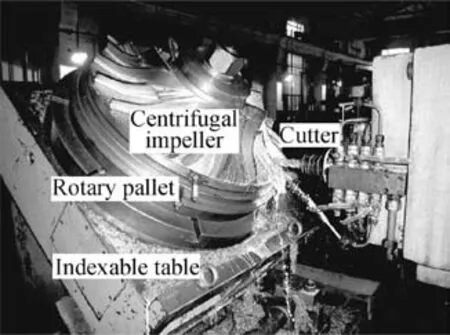
Fig. 1 Illustration of milling a centrifugal impeller on a 4-axis horizontal CNC machine with an indexing table.
According to the aforesaid feature of the indexing table, its structure is a constraint for the tool orientation in impeller machining;a tool orientation satisfying this constraint is feasible. However, current 5-axis methods calculate tool orientations in the part coordinate system without taking the actual machine structure limits into consideration,resulting in unfeasible tool orientations in machining.This work takes the indexing table into account. Before machining impeller blades, the indexing table is set up at a prescribed angle α,and an impeller workpiece is mounted on the pallet. If the largest tool and its corresponding indexing table are appropriately determined,the largest tool can cut a blade patch without colliding with the impeller, so high machining efficiency can be achieved.Therefore,the indexing table angle α should be optimized prior to its set-up in order to use largest-diameter cutters.
With regard to the structure of the machine (see Fig. 2), it can move linearly along the X-, Y-, and Z-axis in the machine coordinate system (the axes are denoted by capital X, Y, and Z), and, simultaneously, the pallet on the indexing table can rotate about its axis,which is called B-axis.The B angle range is 0,360°
[ ]. The offsets between the center of the rotary pallet and the machine coordinate system can be measured as ΔX,ΔY, and ΔZ in the X-, Y-, and Z-axis, respectively. The cutter orientation is always horizontal along the Z-axis of the machine coordinate system. Based on the machine structure,the relationship between the impeller and the machine coordinate system can be found. Thus, tool orientations feasible in the machine structure can be represented in the impeller coordinate system for CNC programming, which is Oxyz (see Fig.2).
2.2. Feasible tool orientation representation in the impeller coordinate system
Since a valid tool orientation, along which the tool can safely cut at a cutter contact(CC)point on the blade surface,should be determined among the feasible tool orientations available in the machine structure, it is important to firstly represent the feasible tool orientations in the impeller coordinate system.According to the impeller workpiece set-up,the impeller coordinate system(the axes are denoted by small x,y,and z)can be identif ied as follows: (1) the origin o is at the center of the rotary pallet, (2) the z-axis is pointing upward and perpendicular to the indexing table, (3) the y-axis is parallel to the Xaxis, and (4) the x- and y-axis are on the indexing table and perpendicular to each other.The machine and impeller coordinate systems are plotted in Fig. 2.
When the rotary pallet rotates by angle B during machining,the tool orientation is on a cone passing through the pallet center with its central-α(see Fig.2). The equation of the tool orientation in the impeller coordinate system is

In 4-axis horizontal CNC milling, the feasible tool orientations are constrained on this cone,so they are represented with angle B of the rotational axis.To machine an impeller blade at a CC point,the selected end-mill has to access this point along one of the feasible tool orientations without the tool gouging/colliding the impeller. This kind of tool orientation is called valid tool orientation,and all valid tool orientations at a blade CC point can be represented with a range of angle B.Hence,it is necessary to search for the angle B range of the valid tool orientations at each blade CC point for a given cutter, which is addressed in the following section.
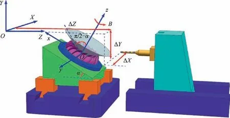
Fig. 2 Structure of a 4-axis horizontal CNC machine with an indexing table.
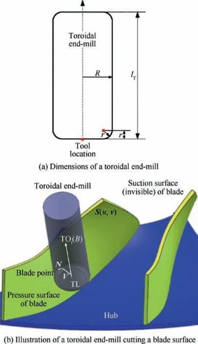
Fig. 3 A toroidal end-mill and its valid tool orientation at a blade CC point.
3. Criteria of a cutter gouging/interfering impeller blades
Given a toroidal end-mill to cut an impeller blade, each blade point corresponds to a B range of the valid tool orientations,along which the end-mill can safely access this point. The B ranges are different at different blade points, and they should be determined in order to f ind the largest cutter to cut the blade.
3.1. Cutter location equations

Based on the valid tool orientation TOIB( )and the unit surface normal N u,v( ),a unit vector V perpendicular to the vector of tool orientation TOIB( ) (see Fig. 3(b)) can be derived as
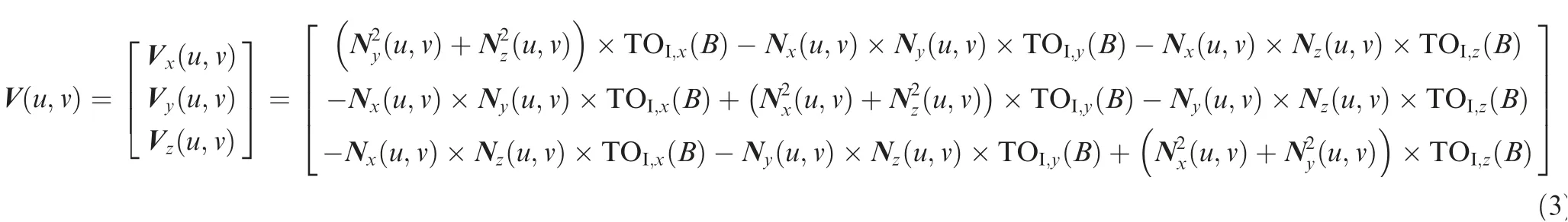
Then,the equation of the cutter location TL(see Fig.3(b))is derived as
3.2.Derivation of the criteria for a cutter gouging/interfering the blades
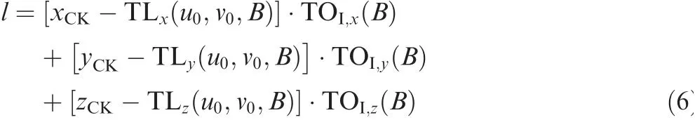
Because of the small tool-accessible space in blade machining,gouge and interference with blade surfaces by a tool often occur,resulting in a scraped part.Hence,gouging and interference detection is indispensable in tool path planning.The main idea is to determine the tool orientation when the tool is cutting a blade CC point and calculate the normal distances between the check points on the surrounding surfaces and the tool axis. If all the distances are longer than the corresponding tool radius, neither gouging nor interference would occur; otherwise, if only one distance is shorter than its tool radius, gouging or interference would occur (Fig. 4). Here, a mathematical representation of the geometric model between the cutter and the impeller surfaces is provided.When the tool is cutting a blade CC point S(u0,v0), the tool axis representation is

where l is the parameter of the tool axis, and its range is l ∈ 0,lT[ ].
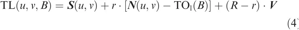
To inspect the tool at S(u0,v0)for gouging and interference,many checking points are sampled from the blade being cut Sand its surrounding surfaces Sk( ),k=1,2,...,mSS,where mSSis the number of surrounding surfaces. In general, the more checking points, the better inspection. However, too many checking points could cause longer
time to inspect. For a checking point [xCK,yCK,zCK], a line passing through this point and perpendicular to the tool axis intersects with the tool axis at a point, whose parameter l is
The distance between the checking point and the tool axis can be calculated as
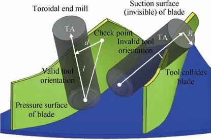
Fig.4 A geometric model of an end-mill gouging and interfering an impeller blade.
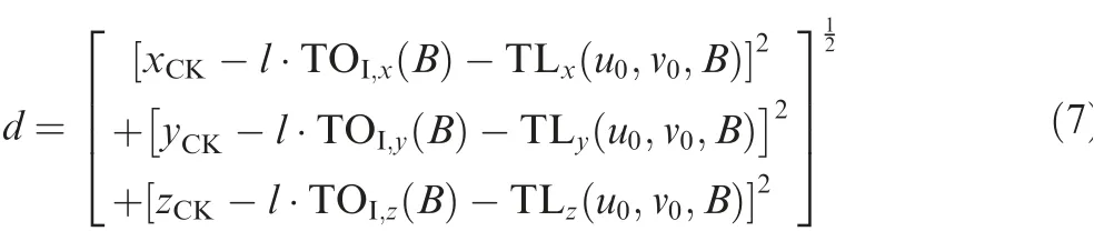
Therefore,gouge and interference can be identif ied by comparing the distance with the corresponding tool radius. If the distance is longer than the tool radius, gouging and interference would not occur;otherwise,they would occur.Therefore,the non-gouging and non-interference conditions are listed in the following equation:
GI B( )=1
If at a blade CC point,Eq.(8)cannot be satisfied,it means that the tool would overcut the impeller in machining.The mathematical representation is a foundation of this approach. By using it,whether the selected toroidal end-mill gouges or collides with the impeller can be found quickly.If the answer is yes,the tool orientation of angle B is invalid;otherwise,angle B is valid.
4. Optimization for the largest cutters diameters and indexing table angles in impeller sectional machining
To machine an impeller,tool-accessible spaces at different CC points on a blade and different locations in a channel vary largely.Thus,it is more eff icient to machine a blade surface patch by patch and a channel section by section using multiple endmills with the largest diameters (called impeller sectional machining), compared to the conventional way of using one small cutter. Therefore, it is signif icant to optimize the largest cutter and the indexing table angle to machine each surface patch or channel section. On a 4-axis horizontal CNC milling machine with an indexing table, an impeller workpiece can be rotated about the axis of the rotary pallet at any angle B,simultaneously with the X-, Y-, and Z-axis motions (see Fig. 1), in order to change the relative orientation between the tool and the blades for more tool-accessible space. Moreover, the indexing table can be fixed at a number of discrete
indexing angles, [α1,α2,...,αmIT] (mITis the angle number),which are independent on the four axes. Thus, by changing the indexing table angle, space for the tool accessing a blade surface patch could be further increased. Therefore, there is an optimal indexing angle, at which the biggest toolaccessible space is available, and the largest-diameter tool can be used to machine this patch.
4.1.Optimization model of the cutter diameter in terms of angle B at a CC point

where Bi∈0,360°[ ], and αjis fixed.
Corollary.

[End]

where Bi∈[0 ,360°], Ri,αj∈ [R1,R2,...,RmT], and

By using an optimization method, the largest tool radiusand the corresponding Birange can be solved. For a special case, if the Birange is void, all available cutters will gouge/collide the impeller when cutting at the CC point.
4.2. Optimization procedure of the largest cutter and thecorresponding indexing table angle for milling a blade surface patch
To improve an impeller’s cutting efficiency and surface quality,the adopted toroidal end-mills are always expected to be as large as possible, though larger tools are prone to gouging and interfering blade surfaces. Since the accessible space of a blade slot varies greatly along the blade surface, an effective solution is to machine a blade surface in several patches by using the corresponding largest cutters. To machine a blade surface patch, two layers of work are nested. The first layer is to optimize the indexing table angles for the largestdiameter tools at all CC points on the patch using the model in Section 4.1 and then f ind the smallest among these largest tools, which can safely cut all CC points. The second layer of work is to change the indexing table angle according to the angles available and repeat the first layer for the smallest tool at a different indexing table angle. Hence, the largest among all the smallest tools is the ideal tool to cut the surface patch at the corresponding indexing table angle.Similarly,this method can be applied to different surface patches, and the blade surface can be eff iciently machined.
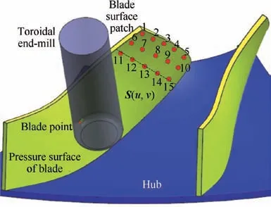
Fig.5 Illustration of optimizing the indexing table angle for the largest cutter to machine a blade surface patch.
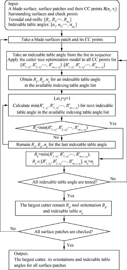
Fig.6 A flow chart of the procedure of optimizing largest cutters to machine a blade surface in patches.
To clearly explain the optimization procedure for the largest tools to cut a blade surface in patches,a flow chart is provided in the following.
5. Approach validation
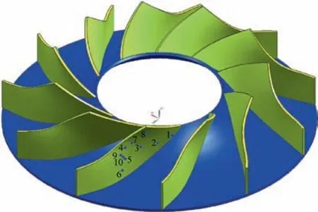
Fig. 7 CAD model of the centrifugal impeller.
In this paper, to demonstrate validity and advantages of this new approach, a centrifugal impeller is adopted in this example, and this approach is applied to determine the largestdiameter cutters and their orientations as well as the optimum indexing table angles,in order to eff iciently machine the impeller in roughing. The impeller has eleven blades evenly distributed along its axis, and their pressure and suction surfaces are designed with free-form surfaces. The space between pressure and suction surfaces varies, the shortest width of the channel is 24.185 mm,and the largest blade height is 39.35 mm. The inner diameter of the impeller is 45.88 mm,the outer diameter is 111.5 mm, and its height is 50.0 mm.The impeller is illustrated in Fig. 7.
The impeller is machined on a 4-axis CNC milling machine with an indexing table, which can be fixed at discrete angles from 20 to 90 degrees in a five-degree interval.Basically,toroidal end-mills with diameters between 10 and 80 mm in a 2-mm interval are available. To cut the pressure surfaces, 100 (10 by 10) CC points are sampled on a pressure surface, and 2900 checking points are sampled on the surrounding surfaces,where the surrounding surfaces are the blade surface and the hub surface which are adjacent to the processed blade surface,and located in the same impeller channel as that of the processed blade surface.By using this approach,the largest cutter and its orientations as well as the optimum table angle are calculated, which will be used to machine the pressure surface with this cutter,and it takes 89.1 min on computation by using a 2.2 GHz dual-core CPU computer. Despite the long computation time, the actual processing time will be shortened, and there are a lot of CPU speed-up methods that can reduce the computation time.To clearly explain the approach procedure,some detailed information is provided in the following.Amongthe CC points, ten are randomly selected, not in sequence along a path. The coordinates of the ten CC points on a pressure surface in the impeller coordinate system are listed in Table 1 and shown in Fig. 7. The largest cutters diameters and their orientations of angle α at three indexing table angles,35, 45, and 55 degrees, are provided in Table 2. It can be observed that the largest cutter for safe cutting at these CC points is 20 mm in diameter, and thus, this cutter is selected to cut the pressure surface.Then,cutter orientations are calculated and listed in Table 3. Since these points are not in sequence, the cutter orientation of angle B is not continuous in the table.In actual machining,the cutter orientation is continuous along tool paths.

Table 1 Coordinates of ten sample CC points on a pressure surface in the impeller coordinate system.
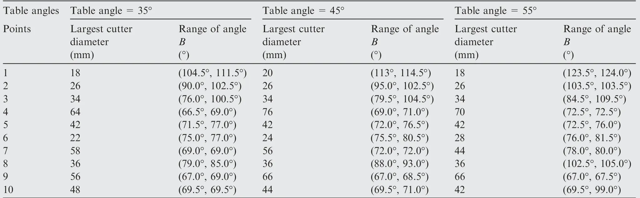
Table 2 Calculated largest cutters diameters and their orientations, angle B, at three table angles for the ten sample CC points.
By applying this approach, the largest cutter is determined as a diameter of 20 mm and a corner radius of 2.0 mm. This cutter is used in rough machining of pressure and suction surfaces. The surface roughness is 0.25 mm. For comparison, a toroidal cutter with a diameter of 14 mm and a corner radius of 1.5 mm is selected. After selecting the cutter, the isoscallop method is used to calculate the tool paths of pressure and suction surfaces in rough milling. Then,a simulation process is conducted using the simulation software VERICUT 7.2.Fig. 8 shows simulation results of blade rough milling using the largest cutter and the selected cutter, respectively. It can be seen from Fig. 8 that the cutting line of the largest cutteris less than that of the selected cutter when milling the blade surface.
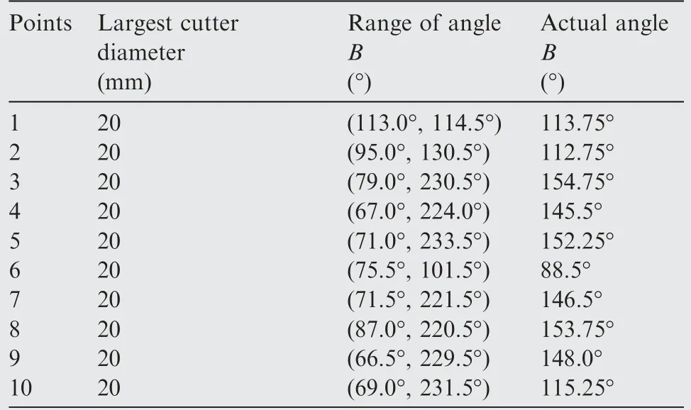
Table 3 Largest cutter and its orientation of angle B to cut the pressure surface (optimum table angle=45°).
In order to illustrate this issue,the tool path lengths of both cutters are calculated by the iso-scallop method, and listed in Table 4. Results show that the tool path length using the largest cutter (677.23 mm) can be reduced by 43.39% compare to the selected cutter (1196.33 mm), which is consistent with the visual display in Fig. 8.
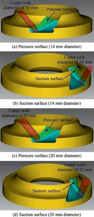
Fig.8 Simulation results of blade rough milling using the largest cutter and the selected cutter.
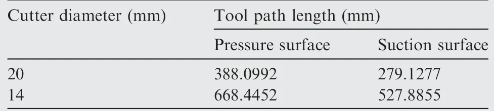
Table 4 Comparison between different tool path lengths.
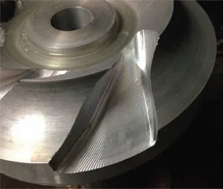
Fig.9 A photo of an impeller machined by using this approach.
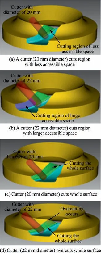
Fig. 10 Comparison between machining using two cutters for patch by patch and using a single cutter for the whole blade.
In order to further illustrate the presented method, a contrast machining test is carried out on a Cincinnati Milacron H5-800 five-axis milling center by using two cutters of different sizes for milling the blade surfaces, respectively. In this machining, the spindle speed is 860 r/min, and the feed rate is 100 mm/min. By using the largest cutter, the time of roughing a suction surface is 11 min,and that of a pressure surface is 12 min. However, by using the selected cutter, the time of roughing a suction surface is 17 min, and that of a pressure surface is 18 min.It is evident that the time of using the largest cutter is about 35% less than that of using the selected cutter.A channel of the impeller is cut and shown in Fig. 9.
To further demonstrate the advantage of this approach, a blade surface can be machined patch by patch with several cutters for higher efficiency. The calculation method of several cutters for patch-by-patch milling is the same as that of a single cutter for the whole blade, since the largest cutter to mill each patch of the blade can be calculated respectively.In this example, two cutters are adopted. A smaller cutter with a diameter of 20 mm cuts the region with a smaller accessible space, and the cusp height of the region is 0.1 mm (Fig. 10(a)). A larger cutter with a diameter of 22 mm cuts the region with a larger accessible space, and the cusp height is 0.06 mm (Fig. 10(b)).Obviously, machining with two cutters is more eff icient than that with one cutter (20 mm diameter) (Fig. 10(c)). However,if the cutter of a diameter of 22 mm is used to cut the whole surface, it could gauge the surface (Fig. 10(d)).
6. Conclusions
In this work, an automated approach of calculating the maximum diameters of multiple cutters and their paths for sectional milling of centrifugal impellers on a 4?-axis machine has been proposed. The scientif ic contributions of this work include (1)a geometric model of a cutter gouging and/or colliding an impeller, (2) an optimization model of the largest diameter and its orientation of a tool cutting a blade-cutter contact point,and(3)an optimization process.By using this approach,an impeller can be machined with largest-diameter cutters section by section to achieve the maximum cutting efficiency. It can directly benef it the manufacturing industry.
Acknowledgements
This study was supported by the National Natural Science Foundation of China (No. 51475328) and the National Science and Technology Major Project of China (No.2015ZX04001202).
 CHINESE JOURNAL OF AERONAUTICS2019年4期
- CHINESE JOURNAL OF AERONAUTICS的其它文章
- Guide for Authors
- CHINESE JOURNAL OF AERONAUTICS
- Residual stresses of polycrystalline CBN abrasive grits brazed with a high-frequency induction heating technique
- Online scheduling of image satellites based on neural networks and deep reinforcement learning
- An evolutionary computational framework for capacity-safety trade-oあin an air transportation network
- Satellite group autonomous operation mechanism and planning algorithm for marine target surveillance