A refined finite element method for bending analysis of laminated plates integrated with piezoelectric fiber-reinforced compositeactuators
J.Rouzegar·A.Abbasi
Abstract This research presents a finite element formulation based on four-variable refined plate theory for bending analysis of cross-ply and angle-ply laminated composite plates integrated with a piezoelectric fiber-reinforced composite actuator under electromechanical loading.The four-variable refined plate theory is a simple and efficient higher-order shear deformation theory,which predicts parabolic variation of transverse shear stresses across the plate thickness and satisfies zero traction conditions on the plate free surfaces.The weak form of governing equations is derived using the principle of minimum potential energy, and a 4-node non-conforming rectangular plate element with 8 degrees of freedom per node is introduced for discretizing the domain.Several benchmark problems are solved by the developed MATLAB code and the obtained results are compared with those from exact and other numerical solutions,showing good agreement.
Keywords Finite element method·Laminated plate·Piezoelectric fiber-reinforced composite(PFRC)actuator·Piezoelectric·Refined plate theory·Smart structures
1 Introduction
In recent years,the importance of piezoelectric materials has significantly increased in a variety of applications such as engineering,aerospace,military,computers,medicine,and automobile structures because of their superior properties such as quick response,large power generation,ability to work at very low temperatures,and vacuum capability.Because of coupled electromechanical properties,they are used as an actuator or sensor in many structures.The piezoelectric effect,a reversible process in piezoelectric materials,is the linear electromechanical interaction between the mechanical and the electrical fields.In sensors,the electric charge is generated with the applied mechanical force(the direct piezo-effect)while in actuators,the mechanical strain is generated from an applied electrical field(the converse piezo-effect).Several piezoelectric materials such as lead zirconate titanate(PZT)and polyvinylidene difluoride(PVDF)are available,but these materials have some limitations such as low piezoelectric constants,shape control(determination of parameters like actuation voltage and actuator orientation configuration,in the way that the structure follows as much as possible the desired shape)and high specific acoustic impedance[1].Because of these limitations,a new material called a piezoelectric fiber-reinforced composite(PFRC)has been introduced[1].In their work,Mallik and Ray[2]used the notion of unidirectional piezoelectric fiber reinforced composite materials and presented their effective properties.
A complete understanding of sensing and actuating capability is essential for the analysis and design of smart structures,because of which many studies have been done on various analyses of hybrid plates with embedded or surface bonded piezoelectric layers.The finite element method(FEM)is an efficient numerical method,which nowadays is widely utilized in modeling and simulation of complicated engineering problems.Many researchers employ FEM for investigation of different behaviors of smart structures.To this end,Mitchell and Reddy[3]developed a hybrid higher-order shear deformation theory(HSDT)for com-posite laminates with piezoelectric laminae.They used an equivalent single-layer theory for substrate and layer-wise theory for piezoelectric laminae.A third-order shear deformation plate theory was employed for the equivalent single layer.Furthermore,Saravanos et al.[4]proposed a finite element solution for laminated composite plates with embedded piezoelectric patches using layer-wise plate theory.Thework of Lam et al.[5]studied bending and free vibration analysis of a smart multilayered plate using the finite element method based on first-shear deformation theory(FSDT).The work by Franco Correia et al.[6]developed higher-order finite element formulations and an analytical closed form solution to study the mechanics of adaptive composite structures with embedded and/or bonded piezoelectric actuators and sensors.Then,Ray and Mallik[7]developed an FSDT finite element formulation for static analysis of smart composite plate.Exact solutions for analysis of multilayered plates containing PFRC actuators were proposed by Malik and Ray[8].An HSDT finite element formulation for active control of adaptive laminated structures was developed by Moita et al.[9].The dynamic response is obtained by the Newmark method,and a feedback control algorithm is used to regulate the forced vibration of the structures.In their work,Cotoni et al.[10]presented a higher-order finite element formulation for the static and dynamic analysis of smart multilayered plates.The nonlinear finite element response of functionally graded(FG)plate integrated with PFRC layer based on the FSDT was analyzed by Panda and Ray[11].The study by Torres et al.[12]derived a formulation for bending analysis of composite laminated plates with piezoelectric layers based on HSDT using the generalized finite element method.A study by Shiekar and Kant[13]presented an analytical solution for cross-ply composite laminates integrated with PFRC actuators under bi-directional bending using a higher-order shear and normal deformation theory(HOSNT12).In their study,Moleiro et al.[14]performed the layer-wise finite element static analysis of smart multilayered composite plates based on the least-squares formulation.The analysis of laminated composite plates integrated with piezoelectric sensors and actuators using HSDT and isogeometric finite elements was presented by Phung-Van et al.[15].A higher-order 2-D/3-D layer-wise finite elements solution for composite and sandwich composite plates with piezoelectric layers under mechanical and electrical loadings was developed by Plagianakos and Papadopoulos[16].Analytical solutions for bending of composite plates[17]and free vibration of FG plates integrated with piezoelectric layers using four-variable refined plate theory was presented by Rouzegar and Abad[18].A layer-wise finite element formulation for free vibration analysis of isotropic plates integrated with piezoelectric patches was presented by Cinefera et al.[19].The refined model was derived from Carrera’s unified formulation,and the mixed interpolation of tensorial component method was used to contrast the membrane and shear locking phenomenon.A time-varying nonlinear formulation based on Reddy’s higher order shear deformation theory for dynamic analysis of piezoelectric laminated composite plate under combined action of aerodynamic load and piezoelectric excitation was developed by Lu et al.[20].Nonlinear dynamic models with two degrees of freedom were obtained by selecting a suitable time-dependent modal function satisfying the displacement boundary conditions and applying second-order discretization using the Galerkin method.
The two-variable refined plate theory is a recently developed shear deformation plate theory that contains only two unknown parameters and predicts parabolic transverse shear stresses across the plate thickness satisfying zero traction conditions on free surfaces.This theory was introduced by Shimpi[21]for bending analysis of isotropic plates and then extended to orthotropic and laminated composite plates by Shimpi and Patel[22],Thai and Kim[23],and Kim et al.[24].Free vibration and buckling analysis of plates was performed by Shimpi and Patel[25]and Kim et al.[26],respectively.Then,Rouzegar and Abdoli[27]presented finite element formulations based of two-variable refined plate theory for bending,free vibration[28],and buckling[29]of isotropic and orthotropic plates.In the two-variable refined plate theory,the plate middle surface is assumed to be unstrained and only the bending effects are considered.In the four-variable refined plate theory,two other parameters associated with in plane displacements of the plate middle surface are added.
The main novelty of this research is developing a finite element formulation based on four-variable refined plate theory for bending analysis of smart laminated composite plates.The PFRC,which is a new and efficient piezoelectric material,is used as an actuator layer,and the hybrid plate is considered under both electrical and mechanical loadings.Another novelty of this paper is introduction of a new 4-node nonconforming rectangular plate element with eight degrees of freedom at each node for discretization of the domain.The presented method is validated by solving several benchmark problems and comparing the results with the exact and FSDT finite element results. The effect of different parameters such as thickness ratio,type of boundary condition,amount of electromechanical loading,and piezoelectric fiber angle are studied.
2 Formulation
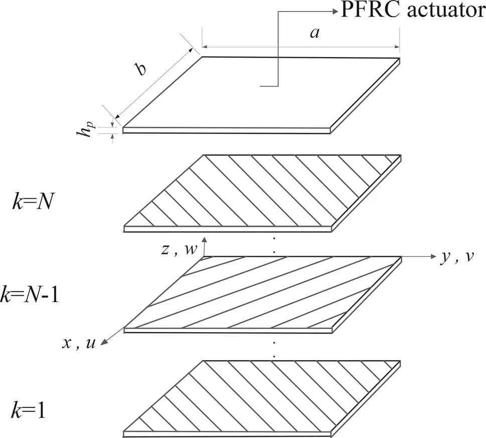
Fig.1 Geometry of the substrate attached with a PFRC actuator at the top
Figure 1 shows a rectangular smart plate with the length of a and width of b containing two parts:the substrate and the piezoelectric layer.The substrate is a laminated composite plate with N orthotropic layers and the PFRC layer is attached at top surface of the substrate.The thickness of substrate layer is h and the thickness of piezoelectric layer is hp,which is small compared to the thickness of the substrate(the ratio hp/h is less than 0.1).A right-hand Cartesian coordinate system(x,y,z)is located at the corner of middle plane of substrate layer and considered as the reference coordinate system.The axes of elastic symmetry in the k-th layer of laminate are oriented at an angle θkwith respect to the referencecoordinate system. The hybrid plate is subjected to both electrical and mechanical loadings.
2.1 Displacement and strain
According to the four-variable refined plate theory,the displacement components u,v,and win x,y,and z directions are described as below[17]:
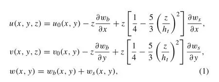
where htis the total thickness of the plate(ht=h+hp).The four variables of the refined plate theory are u0,v0,wb,and wswhere u0and v0are the in-plane displacements of midplane surface in x and y directions,and wband wsare the bending and shear components of transverse displacement,respectively.The strain-displacement relations are also given as below:

in which εxand εyare the normal strains along x and y axes,εxyis the in-plane shear strain and γxzand γyzare the transverse shear strains where

2.2 Coup led constitutive equation
The linear constitutive equations for a single piezoelectric layer that describe the coupling between elastic and electric fields are given as[30]:

where{σ}and{ε}are the stress and strain tensors,[Q]is the stress-reduced stiffness matrix,[e]is the piezoelectric constant matrix,{E}is the electric field intensity vector,[η]is the dielectric constant matrix,and{D}is the electric displacement vector.As seen the stress is divided into the elastic(e)and piezoelectric(p)parts:

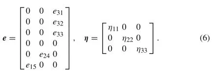
Piezoelectric constant matrix[e]and the dielectric constant matrix[η]for the PFRC layer are given as[7,8]:
The stiffness matrix coefficients Qijfor an orthotropic layer in the principal material directions are functions of engineering constants:

The electric field intensity vector E is derived from electrostatic potential φ as below:

The laminate is made of some orthotropic layers with arbitrary angle of material coordinate respect to laminate reference coordinate system.The constitutive equation of each layer should be written in the laminate reference coordinate as below:

2.3 Electrostatic potential
The bottom surface of the PFRC layer is perfectly attached to the top surface of the substrate and is grounded well.To activate the PFRC layer,electric potential(voltage)is specified at the top surface of the PFRC layer.Because the thickness of the piezoelectric layer is so small the electric potential variation across the thickness is considered linear and consequently the electric potential in the PFRC layer can be expressed as[7]:

where φ0is the applied electric potential function at surface of the PFRC actuator layer(z=h/2+hp).
3 Finite element formulation
3.1 Weak form equations
The minimum potential energy principle is used to derive the weak form of governing equations:

in whichπ is the total potential energy,U is the strain energy,and Vmand Vpare potential energies of external mechanical and electrical loads,respectively.For the plate integrated with the PFRC layer with volume V and m id-plane A,the total potential energy can be written as:

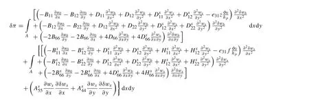
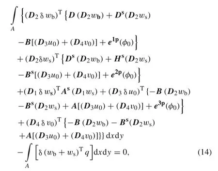
where q is the applied external mechanical force.After substituting strain and stress relations into Eqs.(11)and(12),we obtain:

Setting the variation of the potential energy equal to zero the weak form equation is found as:
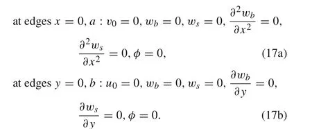
Various boundary conditions for the hybrid rectangular plate are considered as below:
?Fully simply supported(SSSS)plate

?Fully clamped(CCCC)plate:


?Simply-clamped(SCSC)plate:
3.2 Discretized equation
The discretized form of bending and shear components of transversed is placement,wband ws,over the element domain can be written as follows:

where Δwband Δwsare bending and shear nodal degree of freedoms(DOFs)in each element,? and N are interpolation and shape functions,respectively.Also,for the in-plane displacement fields u0and v0and generalized electric potential φ0the discretization over the element domain is expressed by following relations:


where Δu0and Δv0are in-plane DOF vectors along x and y directions and Δφ0is the general electric potential DOF vector.ψ and n are interpolation and shape functions,respectively.
Substituting Eqs.(18)and(19)in Eq.(14)the finite element equations based on four-variable refined plate theory are found as:

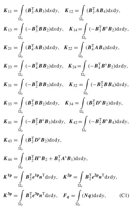
where the stiffness matrix components are defined in“Appendix C”.
3.3 Element design
A four-node non-conforming rectangular element with eight degrees of freedom per node(u0,v0,wb,?wb/?x,?wb/?y,ws,?ws/?x,and ?ws/?y)is suggested for discretizing the domain.The interpolation functions for in-plane displacements u0and v0require C0continuity over the domain.For this purpose,the Lagrangian linear interpolation functions are used for these variables as below:

According to the finite element equations,the bending and shear components of transverse deflection,wband ws,need to satisfy C1continuity across the boundaries of elements.So,wband wsand their derivatives with respect to x and y are chosen as the primary variables and these variables are interpolated over the domain using the following nonconforming Hermit cubic interpolation functions[31]:

in which

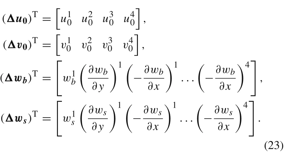
where 2a and 2b are the width and length of rectangular element and(xc,yc)is the coordinate of the m id-point of the element.The developed nonconforming rectangular plate element has totally 32 DOFs where the elemental in-plane and transverse displacements DOFs are:
4 Results and discussion
In this study,a finite element model based on four-variable refined plate theory is presented for bending analysis of smart laminated composite plates. In order to validate the presented approach,an FE code is generated using MATLAB software,and several benchmark problems including laminated composite plates with different boundary conditions under uniformly and sinusoidally distributed transverse loadings are solved.
Example1A laminated composite plate integrated with a PFRC layer at its top surface is considered.The hybrid plate is subjected to mechanical and electrical loadings.The problem is solved by the present FE method,and the obtained results are compared with FSDT finite element[7]and exact[8]solutions.The thickness of each orthotropic layer of laminate,which is made of a type of graphite/epoxy is 1 mm and the material properties are defined in Table 1[8].The thickness of the piezoelectric layer is 250 μm and the material properties of the PFRC actuator are presented in Table 2[2].
The piezoelectric layer consists of two parts:matrix and fibers.The fibers are surrounded by the matrix,so the value of the piezoelectric constant e31,which is in the direction of the fibers is so higher than the other constants;because of this we ignore the other constants in comparison to e31[8].
The results are normalized by the following non-dimensional parameters:

where S=a/h and q0is the amplitude of the applied distributed sinusoidal load(SSL)or the uniformly distributed load(UDL)and value of q0in following examples istaken as q0=?40 N/m2.The electric potential on the top surface of the PFRC layer is also uniformly or sinusoidally distributed with the amplitude of?100,0,or 100 V(volt).Three laminate configurations with following stacking sequences are analyzed:three-layered symmetric[0°/90°/0°],four-layered symmetric[0°/90°/90°/0°]and four-layered anti-symmetric[0°/90°/0°/90°].

Table1 Material properties of substrate layers[8]

Table2 Material properties of piezoelectric layer[2]
Table 3 Normalized in-plane and transverse displacements ū and of symmetric cross-ply square substrate[0°/90°/0°]under sinusoidally distributed mechanical load with and without sinusoidally distributed voltage applied to the PFRC layer

Table 3 Normalized in-plane and transverse displacements ū and of symmetric cross-ply square substrate[0°/90°/0°]under sinusoidally distributed mechanical load with and without sinusoidally distributed voltage applied to the PFRC layer
In the above and in all subsequent tables,values driven in square brackets denote percentage error calculated as follows:[%error]=(calculated value?exact value)/(exact value)×100%
Normalized in-plane and transverse displacements(ū,)and in-plane normal and shear stressesare presented for symmetric cross-ply laminate[0°/90°/0°]in Tables 3 and 4,respectively.Plates with various side to thickness ratios(S=10,20,and 100)are subjected to sinusoidally distributed mechanical and electrical loads.It is observed that the obtained displacements are in good agreement with the exact solution and FSDT-FEM results.In comparison to the exact solution,the presented theory is more accurate than the FSDT-FEM solution in some cases,especially in estimation of transverse displacement.Comparing results of plates with and without applied voltage shows that the actuator is more effective in thick laminates than thin ones.Also,the obtained displacements and stresses are more affected by electrical loads than the mechanical.Both the present FEM and the FSDT-FEM solutions under-predict the transverse displacements and stresses but generally present FEM approach provides better results.
The results of the in-plane and transverse displacement,as well as the in-plane normal and shear stresses of the four-layered symmetric laminated composite plate[0°/90°/90°/0°]are shown in Tables 5 and 6,respectively.The present FE results are in good agreement with the exact solutions especially in the case of thin substrates.The maximum deviation of computedfrom the exact solutions is1.7%for the thick substrate(S=10)under applied voltage.Also,the maximum percentage error in computingandis 8.9%and 6.5%,respectively,for the plates under applied voltage.
Table 4 Normalized in-plane normal and shear stresses and of symmetric cross-ply square substrate[0°/90°/0°]under sinusoidally distributed mechanical load with and without sinusoidally distributed voltage applied to the PFRC layer
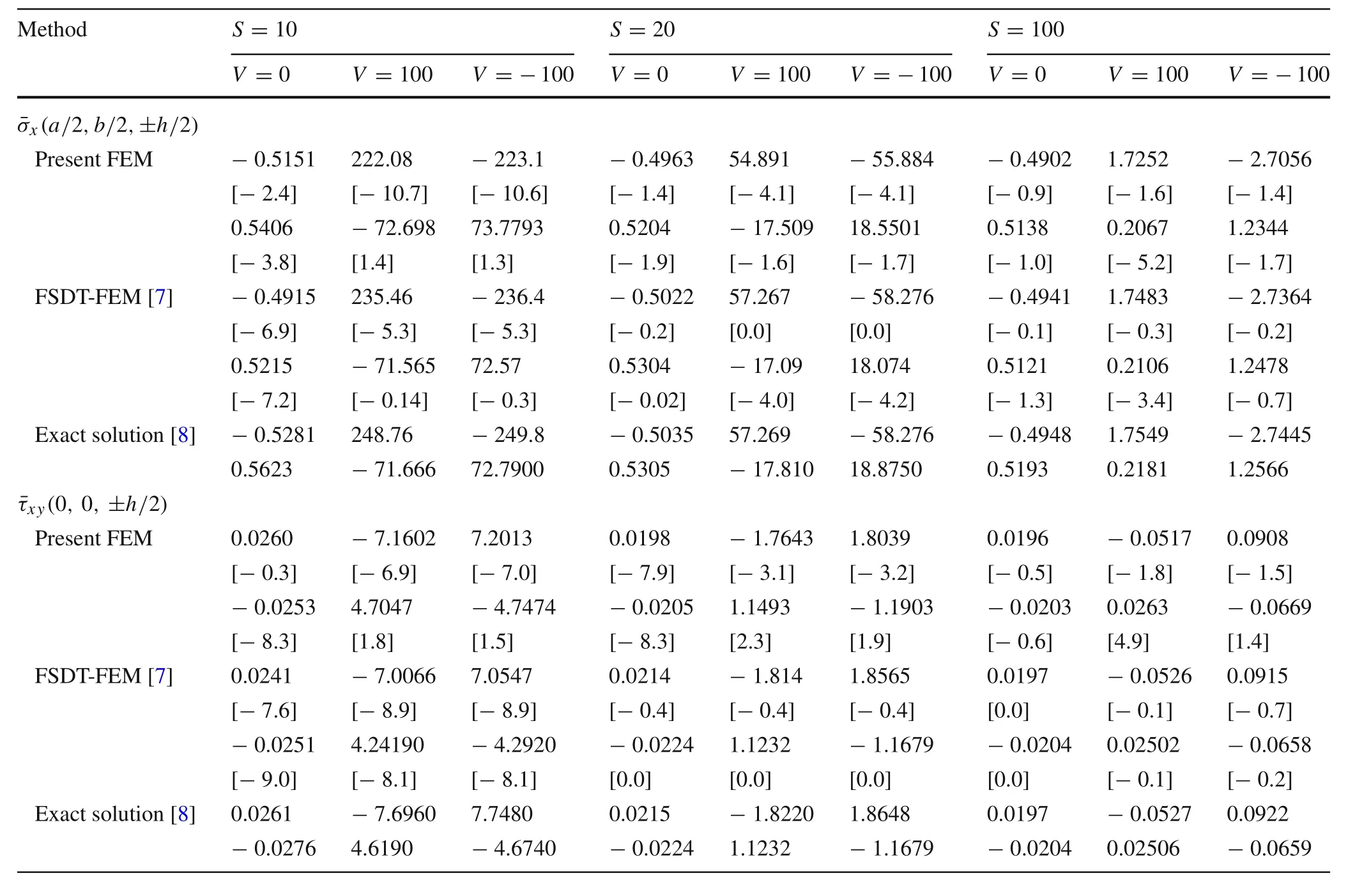
Table 4 Normalized in-plane normal and shear stresses and of symmetric cross-ply square substrate[0°/90°/0°]under sinusoidally distributed mechanical load with and without sinusoidally distributed voltage applied to the PFRC layer
Table 5 Normalized in-plane and transverse displacements and of symmetric cross-ply square substrate[0°/90°/90°/0°]under sinusoidally distributed mechanical load with and without sinusoidally distributed voltage applied to the PFRC layer

Table 5 Normalized in-plane and transverse displacements and of symmetric cross-ply square substrate[0°/90°/90°/0°]under sinusoidally distributed mechanical load with and without sinusoidally distributed voltage applied to the PFRC layer
Method S=10 S=20 S=100 V=0 V=100 V=?100 V=0 V=100 V=?100 V=0 V=100 V=?100ū(0,b/2,±h/2)Present FEM 0.0066 ?2.3891 2.4024 0.0063 ?0.5899 0.6027 0.0063 ?0.0174 0.0300[3.1] [? 6.1] [? 6.4] [0.0] [? 0.5] [? 0.5] [0.0] [1.7] [0.6]?0.0069 0.4932 ?0.5071 ?0.0067 0.1155 ?0.1288 ?0.0066 ?0.0019 ?0.0114[1.4] [? 6.7] [6.6] [0.0] [6.1] [5.4] [0.0] [? 5.0] [1.7]Exact solution[7] 0.0064 ?2.5463 2.5691 0.0063 ?0.5933 0.6059 0.0063 ?0.0171 0.0298?0.0068 0.4619 ?0.4755 ?0.0067 0.1088 ?0.1221 ?0.0066 ?0.0020 ?0.0112(a/2,b/2,0)Present FEM ?0.6783 95.5365 ?96.693 ?0.4729 22.3178 ?23.223 ?0.4126 0.4821 ?1.3073[? 4.2] [1.7] [1.4] [? 3.8] [0.7] [0.4] [? 0.7] [1.0] [? 0.1]Exact solution[8] ?0.7086 93.9010 ?95.318 ?0.4920 22.1410 ?23.125 ?0.4159 0.4772 ?1.3089
Tables 7 and 8 present the displacements and stresses of the four-layered anti-symmetric laminated composite plate[0°/90°/0°/90°],respectively.Again,the results obtained by the presented formulation are in good agreement with the exact and FSDT-FEM solutions and in most cases like thinsubstrate,the present formulation gives more accurate results respect to the FSDT-FE solution.
Table 6 Normalized in-plane normal and shear stresses and of symmetric cross-ply square substrate[0°/90°/90°/0°]under sinusoidally distributed mechanical load with and without sinusoidally distributed voltage applied to the PFRC layer

Table 6 Normalized in-plane normal and shear stresses and of symmetric cross-ply square substrate[0°/90°/90°/0°]under sinusoidally distributed mechanical load with and without sinusoidally distributed voltage applied to the PFRC layer
Table 7 Normalized in-plane and transverse displacements and of anti-symmetric cross-ply square substrate[0°/90°/0°/90°]under sinusoidally distributed mechanical load with and without sinusoidally distributed voltage applied to the PFRC layer
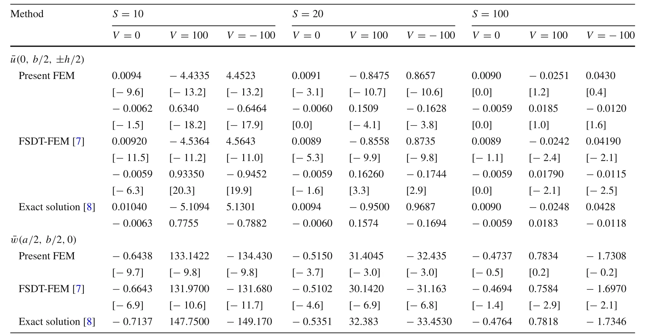
Table 7 Normalized in-plane and transverse displacements and of anti-symmetric cross-ply square substrate[0°/90°/0°/90°]under sinusoidally distributed mechanical load with and without sinusoidally distributed voltage applied to the PFRC layer
Method S=10 S=20 S=100 V=0 V=100 V=?100 V=0 V=100 V=?100 V=0 V=100 V=?100ū(0,b/2,±h/2)Present FEM 0.0094 ?4.4335 4.4523 0.0091 ?0.8475 0.8657 0.0090 ?0.0251 0.0430[? 9.6] [? 13.2] [? 13.2] [? 3.1] [? 10.7] [? 10.6] [0.0] [1.2] [0.4]?0.0062 0.6340 ?0.6464 ?0.0060 0.1509 ?0.1628 ?0.0059 0.0185 ?0.0120[? 1.5] [? 18.2] [? 17.9] [0.0] [? 4.1] [? 3.8] [0.0] [1.0] [1.6]FSDT-FEM[7] 0.00920 ?4.5364 4.5643 0.0089 ?0.8558 0.8735 0.0089 ?0.0242 0.04190[? 11.5] [? 11.2] [? 11.0] [? 5.3] [? 9.9] [? 9.8] [? 1.1] [? 2.4] [? 2.1]?0.0059 0.93350 ?0.9452 ?0.0059 0.16260 ?0.1744 ?0.0059 0.01790 ?0.0115[? 6.3] [20.3] [19.9] [? 1.6] [3.3] [2.9] [0.0] [? 2.1] [? 2.5]Exact solution[8] 0.01040 ?5.1094 5.1301 0.0094 ?0.9500 0.9687 0.0090 ?0.0248 0.0428?0.0063 0.7755 ?0.7882 ?0.0060 0.1574 ?0.1694 ?0.0059 0.0183 ?0.0118(a/2,b/2,0)Present FEM ?0.6438 133.1422 ?134.430 ?0.5150 31.4045 ?32.435 ?0.4737 0.7834 ?1.7308[? 9.7] [? 9.8] [? 9.8] [? 3.7] [? 3.0] [? 3.0] [? 0.5] [0.2] [? 0.2]FSDT-FEM[7] ?0.6643 131.9700 ?131.680 ?0.5102 30.1420 ?31.163 ?0.4694 0.7584 ?1.6970[? 6.9] [? 10.6] [? 11.7] [? 4.6] [? 6.9] [? 6.8] [? 1.4] [? 2.9] [? 2.1]Exact solution[8] ?0.7137 147.7500 ?149.170 ?0.5351 32.383 ?33.4530 ?0.4764 0.7818 ?1.7346
After validation of the method,a three-layered symmetric laminated composite plate[0°/90°/0°]under uniformly distributed electrical and mechanical loading is solved and the obtained results are compared with FSDT-FE solution in Tables 9 and 10.As seen the results of present FE approach are in accordance with those of FSDT-FE solution.Again comparing results of plates with and without applied voltage shows that the actuator is more effective in thick laminates than thin ones.Also,the obtained displacements and stresses are more affected by electrical loads than the mechanical.
A four-layered anti-symmetric angle-ply laminated composite plate[?45°/45°/?45°/45°]is considered.The plateis subjected to uniformly distributed electrical and mechanical loading and the results are compared with FSDT-FE solutions in Tables 11 and 12.As seen again the results of present FE approach are in accordance with those of FSDTFE solution.
Table8 Normalized in-plane normal and shear stresses and of anti-symmetric cross-ply square substrate[0°/90°/0°/90°]under sinusoidally distributed mechanical load with and without sinusoidally distributed voltage applied to the PFRC layer
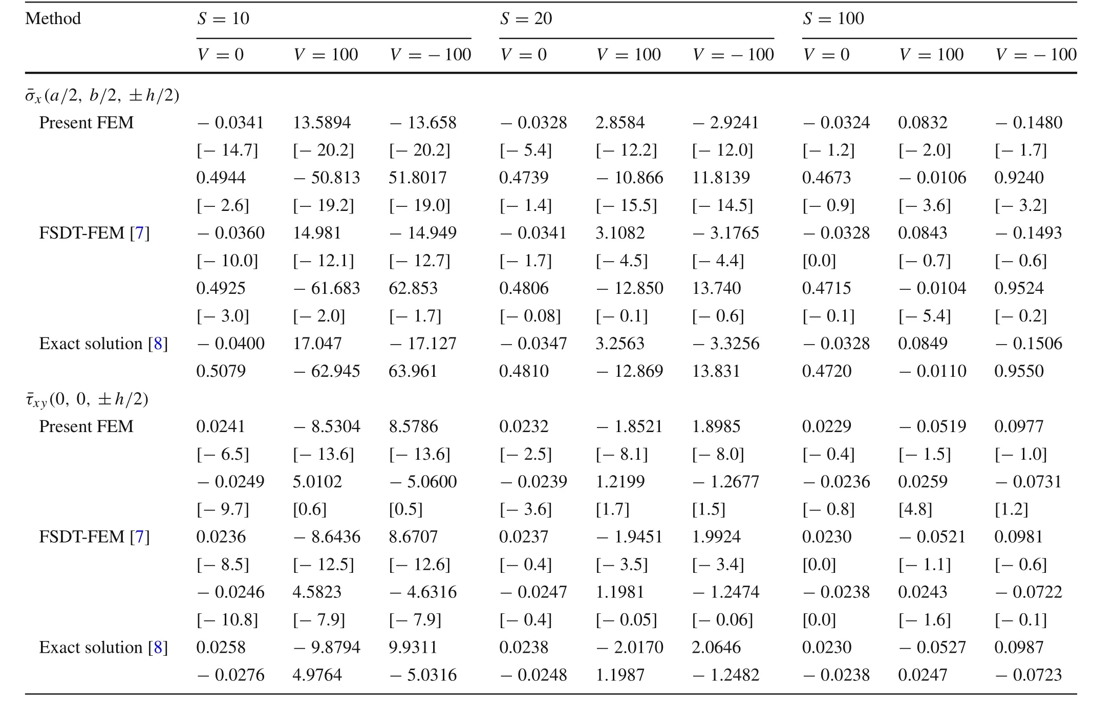
Table8 Normalized in-plane normal and shear stresses and of anti-symmetric cross-ply square substrate[0°/90°/0°/90°]under sinusoidally distributed mechanical load with and without sinusoidally distributed voltage applied to the PFRC layer
Table9 Normalized in-plane and transversed is placementsand of symmetric cross-ply square substrate[0°/90°/0°]under uniformly distributed mechanical load with and without uniformly distributed voltage applied to the PFRC layer

Table9 Normalized in-plane and transversed is placementsand of symmetric cross-ply square substrate[0°/90°/0°]under uniformly distributed mechanical load with and without uniformly distributed voltage applied to the PFRC layer
Method S=10 S=20 S=100 V=0 V=100 V=?100 V=0 V=100 V=?100 V=0 V=100 V=?100ū(0,b/2,±h/2)Present FEM 0.0104 ?5.5588 5.5796 0.0099 ?1.3300 1.3500 0.0098 ?0.0420 0.0616?0.0109 2.5063 ?2.5282 ?0.0104 0.5629 ?0.5838 ?0.0102 0.0107 ?0.0314 FSDT-FEM[7] 0.0092 ?4.8115 4.8300 0.0096 ?1.2062 1.2254 0.0097 ?0.0408 0.0602?0.0098 1.7756 ?1.7952 ?0.0101 0.4475 ?0.4678 ?0.0102 0.0101 ?0.0305(a/2,b/2,0)Present FEM ?0.8706 189.43 ?191.17 ?0.6893 45.161 ?46.539 ?0.6311 1.1806 ?2.4429 FSDT-FEM[7] ?0.9513 166.07 ?167.97 ?0.7044 42.851 ?44.259 ?0.6236 1.1434 ?2.3907
Figures 2 and 3 show the variation of in-plane and transverse displacements across the thickness of simply supported substrate[0°/90°/0°]with the side to thickness ratio of 100,respectively.The plate is subjected to sinusoidally distributed mechanical load as well as sinusoidally distributed electrical load with the amplitude of?100,0,or 100 V.Because the substrate is very thin,ū varies linearly across the plate thickness while the transverse displacement is constant through the thickness,as expected.The obtained displacements are exactly matched to the exact results which show the excellent accuracy of the method.Also,it can be observed that bychanging the polarity of the applied voltage,the PFRC layer causes the reversal effect on the in-plane and transverse displacements of the substrate.
Table10 Normalized in-plane normal and shear stresses and of symmetric cross-ply square substrate[0°/90°/0°]under uniformly distributed mechanical load with and without uniformly distributed voltage applied to the PFRC layer
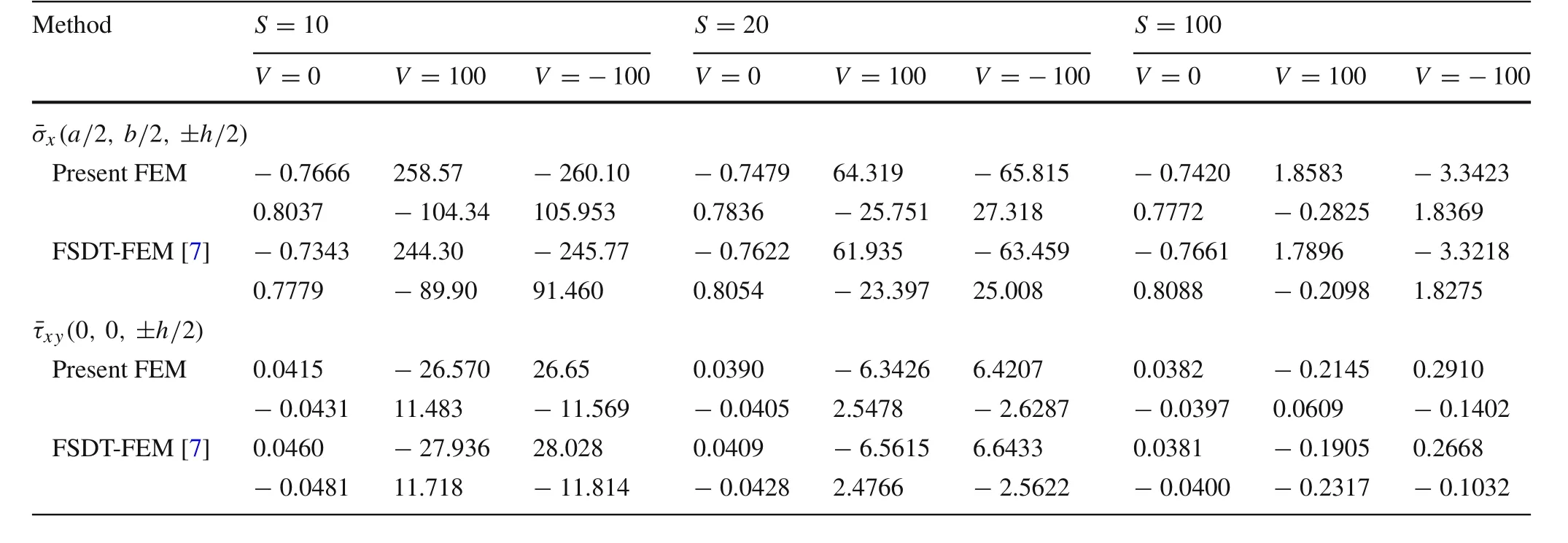
Table10 Normalized in-plane normal and shear stresses and of symmetric cross-ply square substrate[0°/90°/0°]under uniformly distributed mechanical load with and without uniformly distributed voltage applied to the PFRC layer
Table 11 Normalized in-plane and transverse displacements andof anti-symmetric angle-ply square substrate[?45°/45°/?45°/45°]under uniformly distributed mechanical load with and without uniformly distributed voltage applied to the PFRC layer

Table 11 Normalized in-plane and transverse displacements andof anti-symmetric angle-ply square substrate[?45°/45°/?45°/45°]under uniformly distributed mechanical load with and without uniformly distributed voltage applied to the PFRC layer
Method S=10 S=20 S=100 V=0 V=100 V=?100 V=0 V=100 V=?100 V=0 V=100 V=?100ū(0,b/2,±h/2)Present FEM 0.0080 ?3.7218 3.7379 0.0074 ?0.8521 0.8670 0.0072 ?0.0248 0.0393?0.0080 3.7218 ?3.7379 ?0.0074 0.8521 ?0.8670 ?0.0072 0.0248 ?0.0393 FSDT-FEM[7] 0.0073 ?3.8935 3.9081 0.0072 ?0.8169 0.8313 0.0072 ?0.0238 0.0381?0.0073 3.8935 ?3.9081 ?0.0072 0.8169 ?0.8313 ?0.0072 0.0238 ?0.0381(a/2,b/2,0)Present FEM ?0.6866 92.947 ?94.320 ?0.4950 21.389 ?22.379 ?0.4333 0.4220 ?1.2888 FSDT-FEM[7] ?0.6664 81.398 ?82.730 ?0.4847 20.323 ?21.292 ?0.4266 0.4133 ?1.2664
Table12 Normalized in-plane normal and shear stresses and of anti-symmetric angle-ply square substrate[?45°/45°/?45°/45°]under uniformly distributed mechanical load with and without uniformly distributed voltage applied to the PFRC layer

Table12 Normalized in-plane normal and shear stresses and of anti-symmetric angle-ply square substrate[?45°/45°/?45°/45°]under uniformly distributed mechanical load with and without uniformly distributed voltage applied to the PFRC layer
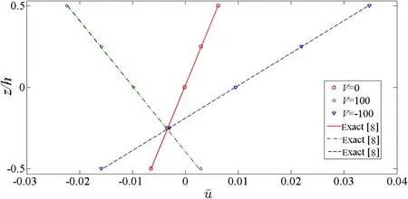
Fig.2 Variation of normalized in-plane displacementthrough the thickness of symmetric substrate[0°/90°/0°]simply supported on all edges(S=100)

Fig.3 Variation of normalized transverse displacementthrough the thickness of symmetric substrate[0°/90°/0°]simply supported on all edges(S=100)
The variation of the normal stressxand the shear stressxythrough the thickness of the substrate are illustrated in Figs.4 and 5,respectively.It is observed that the in-plane normal stress varies linearly in each layer of the substrate with the high accuracy in comparison to the exact solutions.The stress reversal also takes place due to the change in polarity of the voltage applied to the PFRC layer.
Figures 6 and 7 show the variation of transverse shear stresses across the thickness of simply supported substrate[0°/90°/0°]with the side to thickness ratio of 100.As seen the traction free conditions on the free surfaces are satisfied.The theory predicts parabolic variations of transverse strains and stresses across the plate thickness.Because of the different material properties of lam in as,the transverse stresses show jumps on the layers boundaries.
Figure8 illustrates the deflection of the plate along the line y=b/2 for three different boundary conditions.It is seen that the deflection for the SCSC plate is intermediate between the deflections of SSSS and CCCC plates,as expected.

Fig.4 Variation of normalized in-plane normal stressthrough the thickness of symmetric substrate[0°/90°/0°]simply supported on all edges(S=100)

Fig.5 Variation of normalized in-plane shear stressthrough the thickness of symmetric substrate[0°/90°/0°]simply supported on all edges(S=100)

Fig.6 Variation of normalized transverse shear stressthrough the thickness of symmetric substrate[0°/90°/0°]simply supported on all edges(S=100)
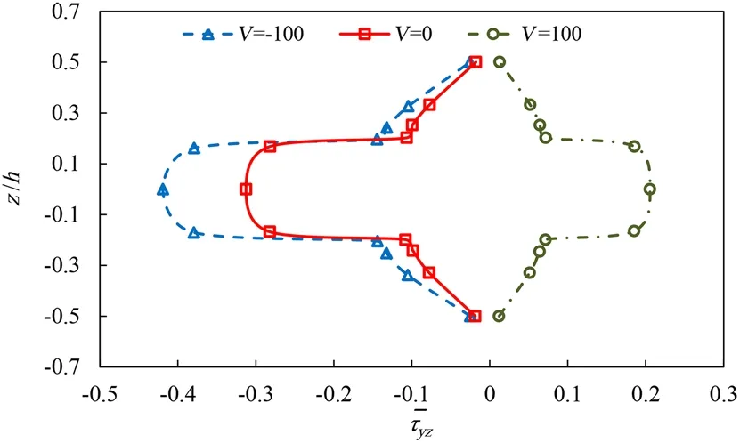
Fig.7 Variation of normalized transverse shear stressthrough the thickness of symmetric substrate[0°/90°/0°]simply supported on all edges(S=100)

Fig.8 Comparison of normalized transverse displacementalong the line of y=b/2 for CCCC,SSSS,and SCSC symmetric substrate[0°/90°/0°]
The piezoelectric properties of PFRC layer is dependent to its fiber orientation ψ .In this part,the effect of ψ(which is the angle of fiber orientation of PFRC with respect to the laminate coordinate system)on the PFRC capability in actuation of three laminated substrates[0°/90°/0°],[0°/90°/0°/90°]and[90°/0°/90°/0°]is investigated.First,these three laminates without any piezoelectric actuation are considered under uniformly distributed transverse pressure,and the central deflection of plates is illustrated in Fig.9.Obviously,the deflections of anti-symmetric square substrates[0°/90°/0°/90°]and[90°/0°/90°/0°]are identical.As seen the variation of ψ has no effect on the carnal deflection of plates without piezoelectric actuation,as expected.Then a constant voltage is also applied to the piezoelectric layer,which consequently the smart laminates are now under uniformly distributed electrical and mechanical loadings.According to Fig.9,for symmetric cross-ply plate[0°/90°/0°/p]the actuation capability of the PFRC layer is maximum when ψ =0°.In the case of anti-symmetric laminated plates([0°/90°/0°/90°/p]and[90°/0°/90°/0°/p])where coupling of bending and extensional deformationoccurs,the response is more sensitive to the variation of ψ.For[0°/90°/0°/90°/p]configuration,the actuation capability of the PFRC layer becomes maximum when ψ =0°where this condition for[90°/0°/90°/0°/p]takes place when ψ =90°which these two configurations are actually identical.

Table13 Material properties of substrate layers[32]

Table14 Material properties of PVDF layer[33]
Example2A three layered[0°/90°/0°]square cross-ply laminate with two piezoelectric layers at the top and bottom surface as actuator and sensor is considered.The substrate is made of 3 mm graphite/epoxy composite layers with the material properties listed in Table13[32].The material properties of PVDF piezoelectric layers are shown in Table 14[33].The thickness of each piezoelectric is 40 μm and the sinusoidally distributed electrical and mechanical loadings are applied to the smart plate.The amplitude of the applied mechanical load is 10 N/m2and the amplitude of the applied electrical load is 100 V.The normalized in-plane displacementsand in-plane normal and shear stressesfor symmetric cross-ply laminate[0°/90°/0°]are compared with the HSDT-FEM results[34]in Table15.It must be men-tioned that in present method the electromechanical coupling effects are neglected and nevertheless the results of present method are in acceptable agreement with the HSDT-FEM solution.
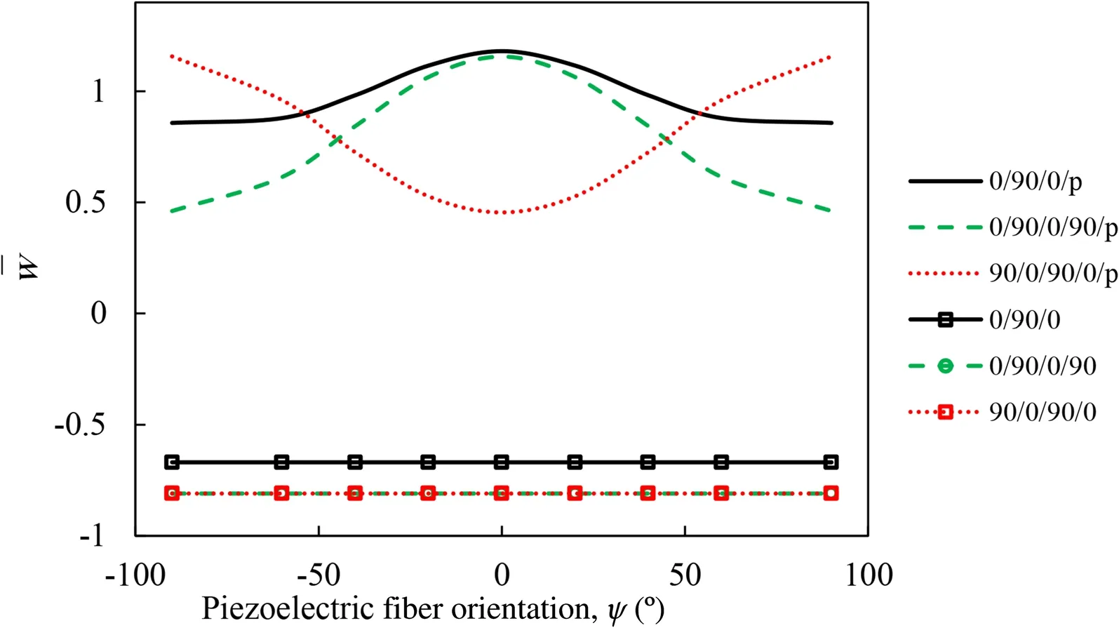
Fig.9 Effect of PFRC fiber angle ψ on variation of central deflection of smart plates
Table 15 Normalized in-plane displacements(ū)and normalized in-plane normal and shear stressesof symmetric cross-ply square substrate[0°/90°/0°]under sinusoidally distributed mechanical load with and without sinusoidally-distributed voltage applied to the PVDF layer

Table 15 Normalized in-plane displacements(ū)and normalized in-plane normal and shear stressesof symmetric cross-ply square substrate[0°/90°/0°]under sinusoidally distributed mechanical load with and without sinusoidally-distributed voltage applied to the PVDF layer
Method S=4 S=10 S=50 V=0 V=100 V=0 V=100 V=0 V=100ū(0,b/2,±h/2)Present FEM ?0.0088 0.3323 ?0.0067 0.0357 ?0.00626 ?0.0052[? 7.36] [? 7.17] [? 8.46] [? 7.51] [? 7.66] [? 8.77]0.0088 ?0.1395 0.0067 ?0.017 0.00626 0.0052[? 7.36] [? 7.49] [? 8.46] [? 8.10] [? 7.66] [? 8.77]HSDT-FEM[34] ?0.0095 0.358 ?0.00732 0.0386 ?0.00678 ?0.0057 0.0095 ?0.1508 0.00732 ?0.0185 0.00678 0.0057x(a/2,b/2,±h/2)Present FEM 0.743 ?26.42 0.567 ?2.83 0.534 0.399[? 6.89] [? 13.3] [? 6.58] [? 12.9] [? 0.37] [0.25]?0.743 12.90 ?0.567 1.47 ?0.534 ?0.453[? 6.89] [7.14] [? 6.58] [? 3.28] [? 0.37] [? 0.87]HSDT-FEM[34] 0.798 ?30.50 0.607 ?3.25 0.536 0.398?0.798 12.04 ?0.607 1.52 ?0.536 ?0.457xy(0,0,±h/2)Present FEM ?0.054 2.912 ?0.026 0.172 ?0.021 ?0.015[1.88] [6.27] [? 10.34] [? 7.52] [? 4.54] [? 6.15]0.054 ?0.762 0.026 ?0.055 0.021 0.018[1.88] [2.69] [? 10.34] [? 1.78] [? 4.54] [? 10.0]HSDT-FEM[34] ?0.053 2.74 ?0.029 0.186 ?0.022 ?0.016 0.053 ?0.749 0.029 ?0.058 0.022 0.02

Fig.10 Variation of normalized in-plane displacement through the thickness of symmetric substrate[0°/90°/0°]with two PVDF layers attached to the top and bottom surfaces(S=10,V=0)

Fig.11 Variation of normalized in-plane displacement through the thickness of symmetric substrate[0°/90°/0°]with two PVDF layers attached to the top and bottom surfaces(S=10,V=100)
Figures 10 and 11 demonstrate the normalized in-plane deflection(ū)of the substrate across the plate thickness without and with the prescribed electric potential applied on the surface of the actuator.The variation of normalized in-plane shear stressacross the plate thickness are compared with results of HSDT-FEM[34]in Figs.12 and 13 without and with applying the electric potential to the surface of the actuator,respectively.Excellent agreement is observed between the results of present FEM and those obtained by the HSDT-FEM[34].Also,it is seen that by applying the electric voltage,the direction of displacements and stresses is reversed.
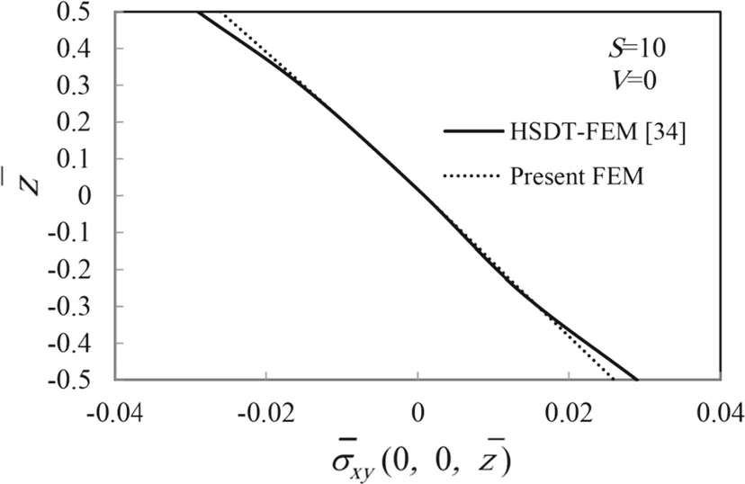
Fig.12 Variation of normalized in-plane stress through the thickness of symmetric substrate[0°/90°/0°]with two PVDF layers attached to the top and bottom surfaces(S=10,V=0)

Fig.13 Variation of normalized in-plane stress through the thickness of symmetric substrate[0°/90°/0°]with two PVDF layers attached to the top and bottom surfaces(S=10,V=100)
5 Conclusions
In this study,a finite element formulation based on four variable refined plate theory is developed for static analysis of cross-ply and angle-ply laminates integrated with a PFRC actuator subjected to mechanical and electrical loadings.This refined plate theory predicts parabolic distribution of transverse shear strains across the plate thickness and satisfies the zero traction boundary conditions on the plate’s surfaces.Unlike classical plate theory(CPT),the presented formulation can be used for both thin and thick plates.After constructing weak form equations of governing equations using the principle of minimum potential energy,a new 4-node,non-conforming rectangular plate element with eight degrees of freedom at each node is introduced for discretization of the domains.The accuracy and efficiency of the present method is demonstrated by solving several benchmark problems and comparing the obtained results with the exact and FSDT finite element solutions for symmetric and anti-symmetric multilayered plates under uniformly and sinusoidally distributed electromechanical loadings.Also the effects of side to thickness ratio,number of layers,staking sequence,type and amount of electromechanical loadings,type of boundary conditions and PFRC fiber orientation on the displacements and stresses are investigated.
Appendix A
The transformed stiffness matrix coefficients for each orthotropic layer are defined as:

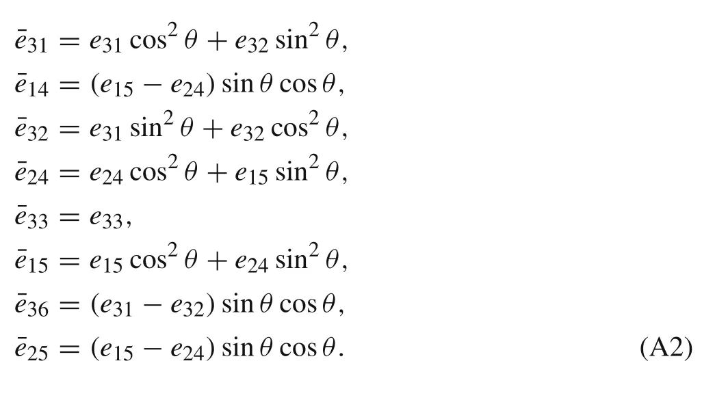
The transformed piezoelectric constants are defined as:
Appendix B
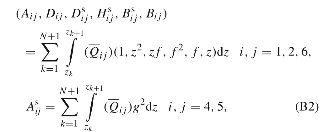
The parameters A,D,Ds,Hs,Bs,B,As,e1p,e2p,e3p,D1,D2,D3,and D4,in Eq.(14)are defined as:



Appendix C
The stiffness matrix components in Eq.(23)are defined as:
where

- Acta Mechanica Sinica的其它文章
- Application of particle splitting method for both hydrostatic and hydrodynamic cases in SPH
- Theoretical analysis for the mechanical behavior caused by an electromagnetic cycle in ITER Nb3Sn cable-in-conduit conductors
- An efficient unstructured WENO method for supersonic reactive flows
- Study of droplet flow in a T-shape microchannel with bottom wall fluctuation
- A novel method for predicting the power outputs of wave energy converters
- Structural eigenvalue analysis under the constraint of a fuzzy convex set model

