Three-point bending of honeycomb sandwich beam s with facesheet perforations
Pengbo Su·Bin Han·Zhongnan Zhao·Qiancheng Zhang·Tian Jian Lu
Abstract A novel square honeycomb-cored sandwich beam with perforated bottom facesheet is investigated under three point bending,both analytically and numerically.Perforated square holes in the bottom facesheet are characterized by the area ratio of the hole to intact facesheet(perforation ratio).While for large-scale engineering applications like the decks of cargo vehicles and transportation ships,the perforations are needed to facilitate the fabrication process(e.g.,laser welding)as well as service maintenance,it is demonstrated that these perforations,when properly designed,can also enhance the resistance of the sandwich to bending. For illustration,fair comparisons among competing sandwich designs having different perforation ratios but equal mass is achieved by systematically thickening the core webs. Further, the perforated sandwich beam is designed with a relatively thick facesheet to avoid local indention failure so that it mainly fails in two competing modes:(1)bending failure,i.e.,yielding of beam cross-section and buckling of top facesheet caused by bending moment;(2)shear failure,i.e.,yielding and buckling of core webs due to shear forcing.The sensitivity of the failure loads to the ratio of core height to beam span is also discussed for varying perforation ratios.As the perforation ratio is increased,the load of shear failure increases due to thickening core webs,while that of bending failure decreases due to the weakening bottom facesheet.Design of a sandwich beam with optimal perforation ratio is realized when the two failure loads are equal,leading to significantly enhanced failure load(up to 60%increase)relative to that of a non-perforated sandwich beam with equal mass.
Keywords Honeycomb sandwich·Facesheet perforation·Three-point bending·Analytical model
1 Introduction
Stiffened plates/shells consisting of ribs and a single panel(facesheet)are commonly found in large-scale structural constructions,such as transportation vehicles,ship hulls and architectural structures,due to convenience in terms of fabrication and high specific strength[1].However,compared with stiffened plates/shells,sandwich structures with honeycomb cores exhibit better bending strength because the second facesheet in a honeycomb sandwich significantly enhances its flexural rigidity[2].Consequently,honeycombcored sandwiches are widely used in architecture,transportation,aerospace,heat transfer,chemical engineering,nanofabrication and,more recently,bio-medicine for their excellent mechanical properties such as high specific stiffness/strength and superior energy absorption[3].In particular,as regular honeycombs have long been identified as one of the most competitive candidates for lightweight constructions[2,4],extensive analytical,numerical and experimental researches have been carried out to characterize the mechanical properties of honeycomb-cored sandwich structures having different topologies and material makes[5–12].
More recently,a range of novel honeycomb structures have been proposed to not only further improve the mechanical properties of these structures but also explore their multifunctional application potentials.For instance,Yu et al.[13]introduced gradient distribution of mass to regular honeycomb sandwich structures and demonstrated that,for enhanced loading capacity,the materials could be more efficiently utilized by introducing the gradient.In another study,Han et al.[14,15]proposed sandwich constructions with honey comb-corrugation hybrid cores and demonstrated,both theoretically and experimentally,that the hybrid core exhibits superiority in both strength and energy absorption particularly in the low density regime.Subsequently,Zhang et al.[16]carried out free vibration analysis of sandwich beams with honeycomb-corrugation hybrid cores.Then too,Oftadeh et al.[17]studied the mechanical properties of anisotropic hierarchical honeycombs and found that increasing the hierarchy order could improve the mechanical properties.Finally,it is worth mentioning that,upon introducing small perforated holes to the facesheet and/or core webs,Han et al.[10]revealed that honeycomb-corrugation cored sandwich panels have superiority not only in specific strength and energy absorption but also in sound absorption and sound proofing.In other words,the proposed hybrid constructions may be classified as acoutomechanical metamaterials for multifunctional applications.
Meanwhile, the bending mechanism of sandwich beams having a variety of lightweight cellular cores has been widely studied. For a typical instance, Han et al. [18] performed design optimization of foam-reinforced corrugated sandwich beams under transverse three-point bending while Rubino et al. [19] carried out three-point bending tests of sandwich beams comprising Y-frame and corrugated cores. In addition, Yan et al. [20] carried out three-point bending tests of sandwich beams with aluminum foam-filled corrugated cores and demonstrated that foam insertions altered not only the failure mode but also increased dramatically its bending resistance.In another instance, Zhang et al. [21] studied experimentally the bending strength, stiffness and energy absorption of composite corrugated core sandwich structures with different fiber types, corrugation angles and core-sheet thicknesses. In addition, Xu et al. [22] proposed graded lattice core sandwich structures and estimated their mechanical strengths and failure mechanisms under bending load, both theoretically and experimentally.More research about the bending mechanism of lightweight sandwich structures can be found in Refs [23–27].
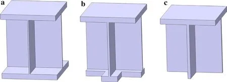
Fig.1 Unit cell of a sandwich beam without perforation,b sandwich beam with perforated bottom facesheet,and c stiffened beam
Nonetheless,in terms of fabrication cost and maintenance convenience,honeycomb sandwich structures are in general inferior to stiffened plates/shells.For instance,arc or laser welding extensively used in the construction of ship hulls/decks[28]can not be used to fabricate honeycomb sandwiches having relatively thick facesheets.Meanwhile, metal corrosion is always an important issue in ocean exploitation,but it is difficult to carry out maintenance checking for all-metallic honeycomb sandwich structures with totally enclosed cells.It is,therefore,natural to ask the question whether there exists a lightweight structure that combines the performance superiority of honeycomb sandwiches with the low fabrication cost and easy maintenance of stiffened plates/shells.The present study aims to answer this question by introducing perforations to one of the facesheets of a square honeycomb sandwich and comparing its resistance to three-point bending with that of the non-perforated one.
The contribution of the back face to the bending response of sandwich beams with corrugated and Y-frame cores was investigated by St-Pierre et al.[29].They demonstrated that sandwich beams absent a back face are stronger than those with front-and-back faces in a short span beam while the opposite holds in the case of a long span beam.Inspired by this work,a square honeycomb-cored sandwich beam with square perforations on its bottom face is proposed,as shown in Figs.1 and 2.Relative to the small perforations(sub-millimeter scale)introduced by Han et al.[10]for the purpose of absorbing sound energy,the perforations of Figs.1 and 2 are sufficiently large to facilitate not only the fabrication but also maintenance during service.For engineering applications like the decks of cargo vehicles and transportation ships,the design of large-scale sandwich constructions with facesheet perforations requires a relatively thick top facesheet to avoid local indentation failure(due to,e.g.,large concentrated load transported via the wheel of a heavy vehicle)so that considerable bending strength can be achieved.Meanwhile,introducing perforations to the sandwich design facilitates not only the fabrication process(e.g.,laser welding)but also, for certain applications,manual service maintenance during severe marine corrosive environments.As a result,w ill these perforations positively affect the mechanical properties of the sandwich and,if so,whether there exists optimal perforations for maximum strength are the two major issues that concern the present study.
The paper is organized as follows.Firstly,the concept of a perforated all-metallic sandwich beam with square honeycomb core is introduced and the key geometrical parameters describing its topology are presented.For comparison,hon-eycomb sandwich beams without perforation and absent a back facesheet are also considered,subject to the constraint of equal mass.An other constraint is that the sandwich beams with or without perforations have relatively thick top facesheets so that local indentation failure does not occur.Secondly, finite element(FE)simulations are carried out to quantify the influence of perforations on the strength of the sandwich beam subjected to three-point bending.Subsequently,analytical formulae are developed to predict the failure loads corresponding to different failure modes of the perforated sandwich.The analytical predictions are compared with the results obtained from full FE simulations,and optimal perforations for maximum strength enhancement are identified.Finally,the sensitivity of failure loads to the ratio of core height to beam span is discussed for varying perforation ratios.

Fig.2 a Perforated honeycomb sandwich beam subjected to three point bending.b Unit cell of perforated sandwich beam.c Bottom view of unit cell
2 Perforated sandwich beam in three-point bending
Figure 2 presents the geometric parameters of a square honeycomb-cored sandwich beam with square perforations on its bottom facesheet and the corresponding unit cell.As for a conventional sandwich beam without perforations,the beam span L,the thickness of facesheet tf,the thickness of core webs tc,the height of core webs Hc,and the width of a unit cell Lc(Fig.2b)are used to characterize the topology of the perforated sandwich beam.Furthermore,the perforation ratio ω(area ratio of perforations to the intact faceshteet)and the width of the bottom facesheet after perforation Lb(Fig.2c)are introduced to describe the square perforation.Let V2/(EM)denote the non-dimensional loading intensity,where E is the Young modulus of the material,M is the maximum moment,and V is the maximum shear force,both per unit width[30].

Table 1 Initial geometrical parameters of a perforated sandwich beam under three-point bending
With reference to the unit cell shown in Fig.2c,the perforation ratio is defined by

To maintain the same mass as the non-perforated sandwich,the thickness of core webs in the perforated sandwich is increased as

where

Here,tc0is the thickness of honeycomb core webs when ω=0,and Nholesand Ncoresare the number of perforations in the facesheet and the number of unit cells in the sandwich beam shown in Fig.2,respectively.
The width of the perforated bottom facesheet can be written as

For the current study,the initial geometrical parameters of the sandwich beam are listed in Table 1.In consideration of specific applications(e.g.,the deck of transport ships and cargo carriers)that require a relatively thick facesheet to avoid local failure such as yielding and buckling,once the initial thicknesses of the facesheet and core webs are specified,the core would most likely fail ahead of the facesheet.As the main purpose of this study is placed upon the concept of the face perforation and its effects on sandwich strength under three-point loading,systematic variation of geometrical and loading parameters is not performed.Further,with reference to Fig.2,it is assumed that the rigid puncher has a sufficiently large width 2a relative to cell width Lcso that local indentation failure does not occur,and that the puncher is placed directly above the node connecting the honeycomb core to the top face.Under such conditions,the sandwich under three-point bending would fail in two main modes:(1)bending failure,i.e.,yielding of beam cross-section and buckling of top face caused by the bending moment;and(2)shear failure,i.e.,yielding and buckling of core webs due to shear force.Meanwhile,as above mentioned,local indentation is not considered.
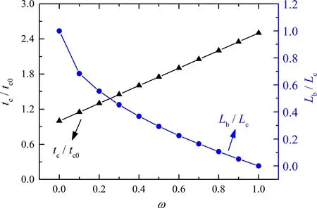
Fig.3 Thickness of core webs and width of perforated bottom face plotted as functions of ω
From Eq.(2),the thickness of core webs varies linearly with ω.Meanwhile the width of the perforated face,Lb,varies linearly withω as shown in Fig.3.When ω =0,the sandwich is intact without perforation,as shown in Fig.1a.When ω=1,the sandwich has no bottom facesheet,i.e.,it degrades to the stiffened plate of Fig.1c.With ω taking values in the range of 0?1,the perforated area of the bottom face increases as ω is increased,resulting in the increasing thickness of core webs tcand decreasing width of bottom face Lb.
3 FE simulations
3.1 FE model
FE simulations of perforated sandwich beams in three-point bending as illustrated in Fig.2 are carried out with the commercial FE code ABAQUS/Explicit.The sandwich beam consisting of two unit cells along its width is employed for the simulation.Four-node shell elements(S4R)with five integration points through the thickness are used to model the core webs,and there are 30 layers of elements along the height direction.Eight-node solid elements(C3D8R),1mm×1mm×0.2mm in size,are used to model the facesheets.Four-node rigid elements(R3D4),2 mm×2 mm in size,are used to model both the puncher and roller in three point bending.A mesh sensitivity study shows that further mesh refining does not improve the numerical accuracy of the results.
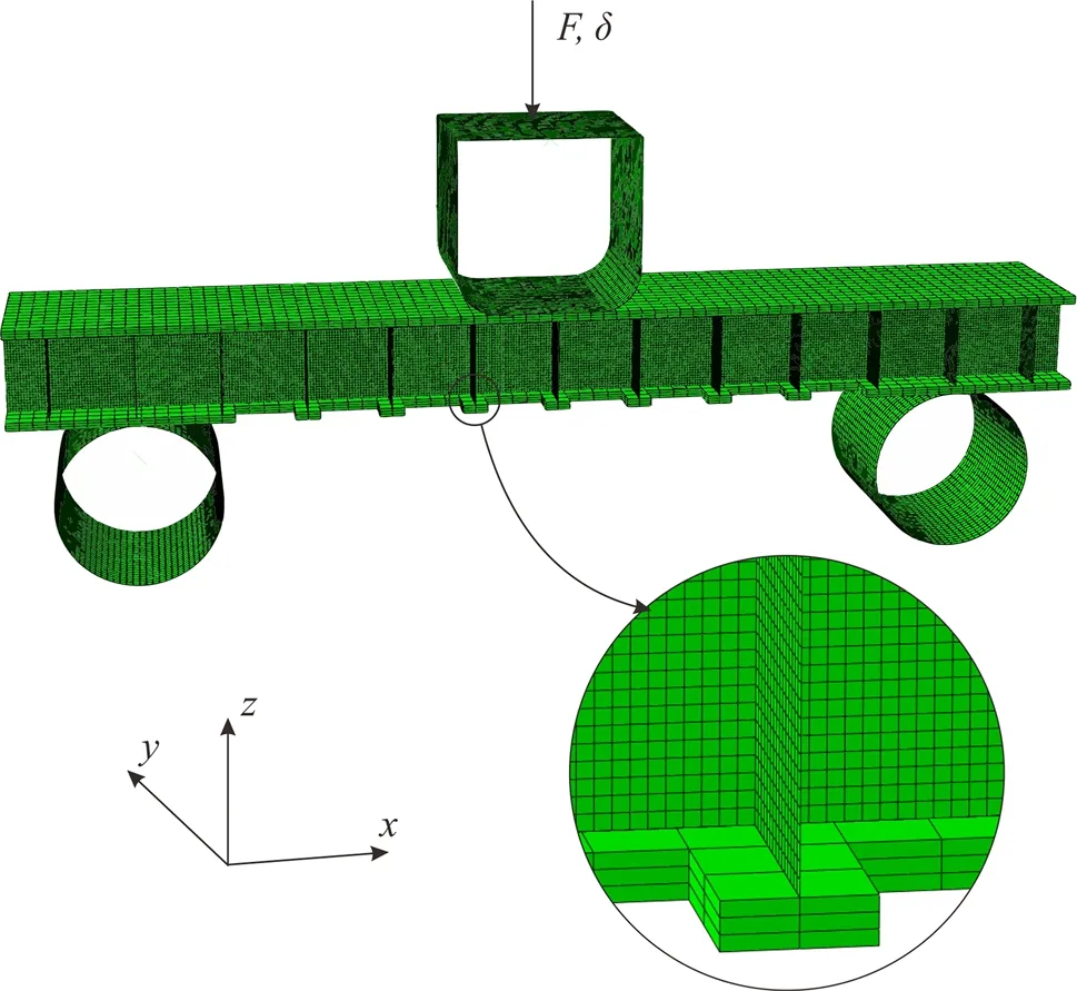
Fig.4 Sandwich model for FE simulation
Both the facesheets and core webs of the sandwich beam are made of 304 stainless steel(density ρs=8000 kg/m3,Young modulus Es= 210GPa,and yield strength σs=210 MPa),which is assumed to obey the J2-fl ow theory once yielding is initiated,with strain hardening ignored for simplicity.
Quasi-static three-point bending is applied to the sandwich beam with a rigid puncher.The whole FE model is shown in Fig.4.Note that the bottom facesheet directly above the rollers is not perforated.
3.2 Results of FE simulations
The influence of perforation ratio on the strength of a perforated sandwich beam is firstly discussed,with the strength interpreted as the reaction force of the puncher when the beam fails.Figure5 a plots the normalized reaction for ceversus the displacement of the puncher.The deformation of the sandwich is elastic at the beginning.Once the elastic limit is reached,the sandwich enters the plastic regime,which can be regarded as total failure as strain hardening is not ignored.In Fig.5a,the value of the perforation ratio(ω)is marked on each load-displacement curve.The beam with ω=0.25 has the highest strength,whereas that having ω=1 exhibits the lowest strength.More details are shown in Fig.5b,which displays the normalized strength as a function of ω.When ω≤0.25,the strength increases with increasingω and peaks when ω =0.25.Afterwards,the strength decreases as ω is further increased.Ultimately,the strength reaches the minimum as ω approaches its limiting value 1 that corresponds to the case when the whole bottom facesheet disappears(i.e.,the sandwich beam degrades to a stiffened beam).
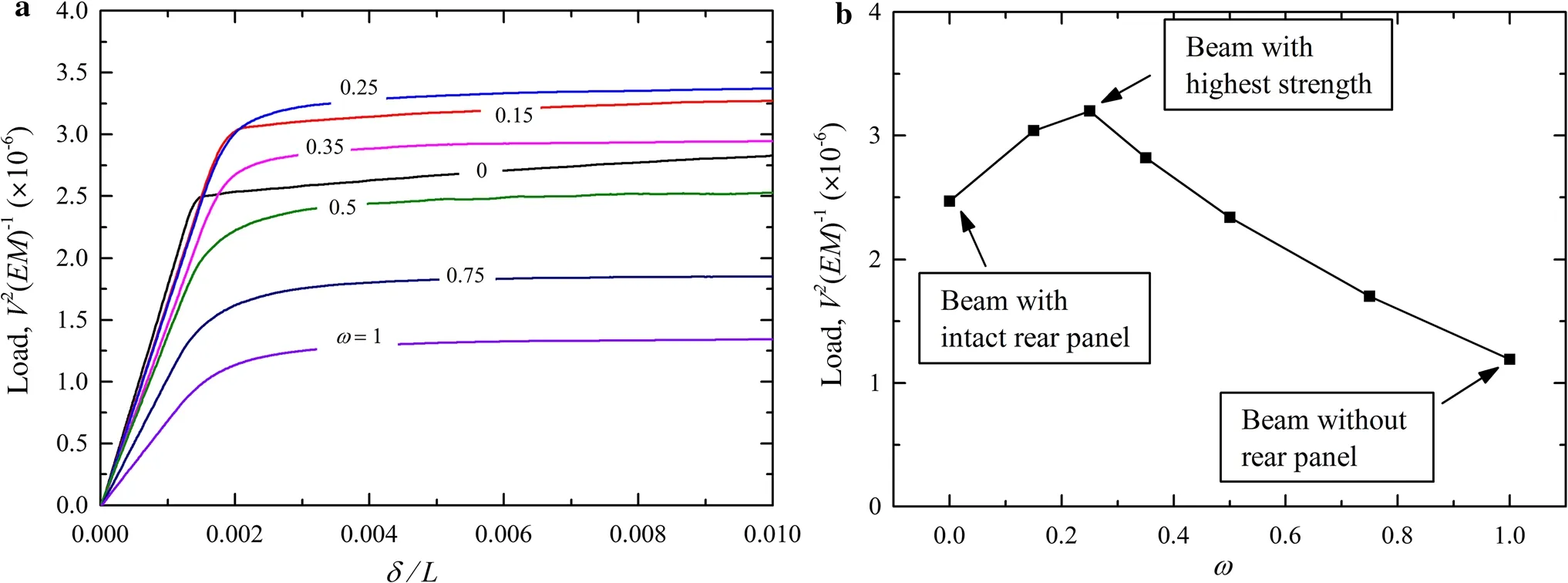
Fig.5 Sandwich beam with perforated bottom face(rear panel)under three-point bending.a Load versus deflection curves for selected values of perforation ratio ω.b Normalized sandwich beam strength plotted as a function of ω (Load:reaction force in puncher;δ:displacement of puncher;M:moment per unit width;V:transverse shear force per unit width.)
The physical mechanism underlying the variation trend in Fig.5b can be explained as follows.For a given perforation ratio,the beam fails with the smaller load of either shear or bending.For instance,the beam with intact bottom facesheet fails in shear,since the bending failure load is larger than that of shear failure.When the perforation ratio ω is increased,the area of perforations in the bottom facesheet becomes larger and the thickness of the core webs increases,resulting in a weaker facesheet but a stronger core.Consequently,the bending failure load decreases while the shear failure load increases.At a specific point,simultaneous bending failure and shear failure of the perforated beam occur,thus allowing the beam to reach the highest strength.
To explore the failure modes,the distribution of Mises stress in sandwich beams with different perforation ratios at the occurrence of failure is presented in Fig.6.When ω=0,the beam fails in shear.As ω is increased,the area of the perforated holes and the thickness of the core webs both increase,resulting in a stronger core and a weaker bottom facesheet,which in turn leads to a higher shear strength and a lower bending strength.When ω is increased to 0.25,the shear failure load is equal to the bending failure load:correspondingly,the beam acquires its maximum strength.This maximum strength and its dependence on beam configuration will be investigated further in the next section using analytical predictions.
4 Analytical predictions
In this section,analytical formulas for the failure loads of perforated sandwich beams under three-point bending are presented.

Fig.6 Distribution of Mises stress in honeycomb-cored sandwich beams with different perforation ratios at the occurrence of failure
4.1 Bending failure
When subjected to three-point bending,the sandwich beam can fail in bending failure,i.e.,yielding of its cross-section or buckling of its top face.Conventionally,in the absence of perforation,only face yielding is induced by the bending moment.In this study,however,yielding of honeycomb core due to bending moment is taken into consideration because the presence of perforations causes the moment acting on core webs to be non-negligible.As shown in Fig.7,when ω is zero or small,the neutral axis is located in the core;when ω is large,however,the neutral axis is shifted to the top facesheet.

Fig.7 Schematic of sandwich cross-section under three-point bending.a When ω is zero or small,the neutral axis is located in the core.b When ω is large,the neutral axis is shifted to the top face
In Fig.7,d is the location of the neutral ax is which divides the beam cross-section into two regimes:the blank regime is in compression while the shaded regime is undergoing tension when the beam is subjected to three-point bending.When the whole cross-section enters yielding,the beam loses the capacity of loading.Stress equilibrium in the cross section dictates that

Due to stress equilibrium, the neutral axis divides the sandwich cross-section into two regions of identical area so that the location of the neutral axis can be determined using simple geometrical calculations,as

When ω is zero or small,the neutral axis is located in the central portion of the core;when ω is large,the neutral axis is shifted to the top face.The critical perforation ratio ω0corresponding to the case when the neutral axis is just shifted to the top face can be obtained as

Correspondingly,the moment applied in the cross-section when the beam fails is given by

The failure load for the yielding of perforated beam subjected to three-point bending can then be obtained as

In addition to face or core yielding,panel buckling(PB)occurs in the top face,which is also a possible failure mode[31].The corresponding failure load can be expressed as

4.2 Shear failure
Due to the shear force applied in the beam under bending,the honeycomb core can fail in either shear yielding or shear buckling[31].For a perforated sandwich beam under three point bending,its failure load of shear yielding can be written as

while its failure load of shear buckling can be given as

where

and tcis defined in Eq.(2).
4.3 Comparison between analytical predictions and FE simulations
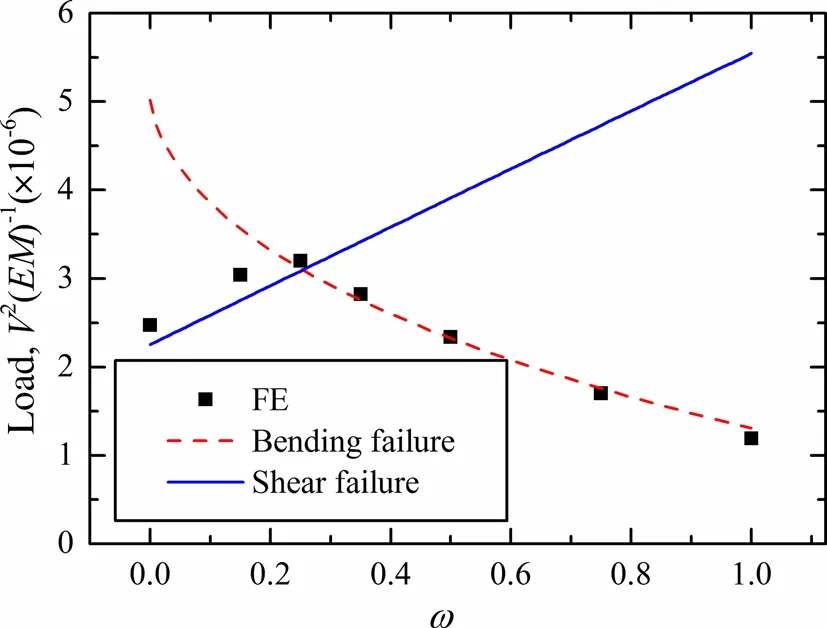
Fig.8 Comparison between analytical predictions and FE simulations for failure loads of perforated sandwich beam plotted as functions of perforation ratio
The failure loads of sandwich beams with varying perforation ratios are obtained using both analytical predictions and FE simulations,and the results are shown in Fig.8.For the sandwich beams investigated in the current study,panel buckling and core shear buckling do not happen and thus are neglected in Fig.8.
As can be seen from Fig.8,for both bending and shear typesof failure,the failure loads obtained from analytical predictions and FE simulations compare well with each other.For a given perforation ratio,the beam fails with the smaller load of shear or bending.For instance,the beam with intact bottom face(ω=0)fails in shear,since the bending failure load is larger than that of shear failure.Whenω increases,the area of perforations in the bottom face becomes larger and the thickness of the core webs increases,resulting in a weaker face and a stronger core.Consequently,the bending failure load decreases while the shear failure load increases.At a certain stage,the perforated beam initiates bending failure and shear failure simultaneously,thus reaching its maximum(optimal,though somewhat naive)strength.Let ωoptrepresent the corresponding perforation ratio.As the perforation ratio is further increased,bending failure dominates and the beam failure load decreases.
4.4 Effects of core height to beam span ratio on maxim um strength and optimal perforation ratio
For the perforated sandwich beams considered in the present study,it has been demonstrated that their failure loads can be adequately evaluated using analytical predictions of both the bending and shear failures.Next,the dependence of bending strength and shear strength upon beam aspect ratio Hc/L is quantified.Figure 9a plots the bending and shear failure loads as functions of perforation ratio ω for selected values of Hc/L in the range of 0.07–0.16.Corresponding results obtained from FE simulations and theoretical analysis are presented in Table 2.These results show good agreement between simulations and theoretical analysis.Initially,the failure load is seen to increase nearly linearly with increasing ω and the beam fails in shear at its infancy.Then,the failure load peaks when the perforation ratio is optimized at ωopt.Beyond this optimal perforation ratio,the failure load decreases with increasing ω and the beam fails in bending for all selected values of Hc/L.
Figure 9b shows that ωoptincreases almost linearly with Hc/L.For a long beam with small Hc/L,ωoptis small and tends to zero,which means the facesheet perforations do not significantly strengthen the beam.In contrast,for a short beam with large Hc/L,ωoptis large and tends to 1,which means the perforated holes significantly enhance the beam strength.To be more specific, for a perforated sandwich beam with ωopt,the ratio of its failure load to that of the nonperforated one is plotted as a function of Hc/L in Fig.9b.Again,as far as bending strength is of concern,it is seen that facesheet perforations are more beneficial to short beams rather than the long ones.
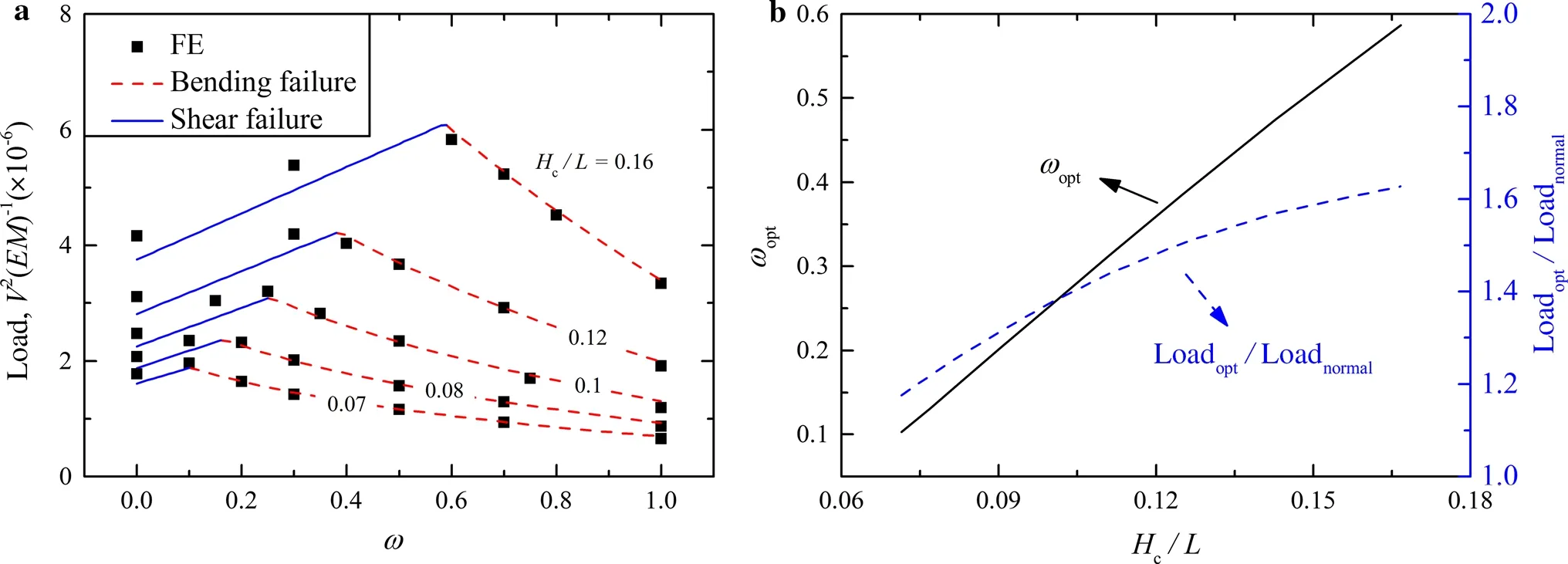
Fig.9 a Normalized failure load plotted as a function of perforation ratio (ω) for selected values of beam aspect ratio(H c/L).b Optimal perforation ratio and failure load ratio of perforated sandwich beam to an intact one plotted as functions of H c/L
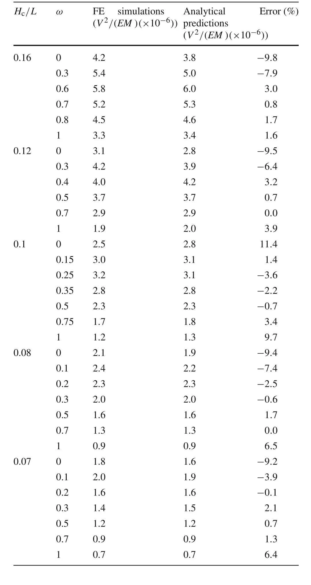
Table 2 Error analysis of results obtained from simulations and theoretical analysis
Finally,it should be pointed out that because the main focus of the present study is placed upon practical applications like the decks of cargo vehicles and transportation ships,the failure of the upper facesheet is not allowed by specifying sufficiently large initial thickness of the upper facesheet.Under such conditions,the core would most likely fail ahead of the facesheet.In a future study, systematic variation of geometrical and loading parameters will be carried out to reveal if the proposed design still has advantages if the failure of the upper facesheet occurs.
5 Concluding remarks
The concept of facesheet perforations has been proposed to enhance the resistance of square honeycomb-cored sandwich beams to three-point bending,in addition to facilitating fabrication procedures and access for maintenance during service.Both FE simulations and analytical modeling are used to evaluate the concept,with good agreement achieved between predictions obtained using the two approaches.Targeting applications like the decks of cargo vehicles and transportation ships,failureof the top facesheet such as local indentation is not allowed by specifying sufficiently large initial thickness of the upper facesheet.Two main failure modes,bending failure and shear failure,then occur in the perforated sandwich beams.The corresponding failure loads are characterized as functions of the perforation ratio.
The shear failure load is found to increase with increasing perforation ratio because of a stronger core,for the mass of the perforated sandwich beams is fixed as the perforation ratio is varied.In contrast,the bending failure load decreases with increasing perforation ratio due to a weaker bottom facesheet.Consequently,when the two types of failure load are equal,the perforated sandwich beam reaches its maximum strength,which can be up to60%higher than that of the non-perforated one with equal mass:the corresponding perforation ratio is then optimal.The optimal perforation ratio increases as the beam aspect ratio is increased,and so is the strength enhancement relative to the non-perforated beam.In other words,with the core height fixed,facesheet perforations are more beneficial to short sandwich beams rather than long ones.Results obtained in the current study can help the design of large-scale sandwich constructions for applications like the decks of cargo vehicles and transportation ships where sandwich plates/shells with relatively thick facesheets are required.
AcknowledgementsThis work was supported by the National Natural Science Foundation of China(Grants 11472209,11472208),the China Postdoctoral Science Foundation(Grant 2016M 600782),the Postdoctoral Scientific Research Project of Shaanxi Province(Grant 2016BSHYDZZ18),the Fundamental Research Funds for Xi’an Jiaotong University(Grant xjj2015102),and the Jiangsu Province Key Laboratory of High-end Structural Materials(Grant hsm1305).
- Acta Mechanica Sinica的其它文章
- Application of particle splitting method for both hydrostatic and hydrodynamic cases in SPH
- Theoretical analysis for the mechanical behavior caused by an electromagnetic cycle in ITER Nb3Sn cable-in-conduit conductors
- An efficient unstructured WENO method for supersonic reactive flows
- Study of droplet flow in a T-shape microchannel with bottom wall fluctuation
- A novel method for predicting the power outputs of wave energy converters
- Structural eigenvalue analysis under the constraint of a fuzzy convex set model

