Anharmonic 1D actuator model including electrostatic and Casimir forces with fractional damping perturbed by an external force
Maryam Mansoori Kermani·Maryam Dehestani
1 Introduction
Nanoelectro mechanical systems(NEMS)have turned into a critical topic due to their significant effect on many aspects of technology and science.The beam-type actuators are the fundamental components of the NEMS and are constructed from two conductive electrodes so that one of them is fixed and another one is movable. The electrodes are separated by a dielectric spacer. Applying a voltage induces an electric field between the electrodes via the electrostatic charges on the surface of the electrodes.The difference in the applied voltages causes the movable upper electrode to deflect downward to the fixed electrode because of the electrostatic attraction.There is a special voltage so that the movable electrode will be unstable and pulls-in onto the fixed electrode.The voltage and deflection of the actuator then are called the pull-in parameters.The reader is referred to Refs.[1]and[2]to review the studies on the pull-in instability.Because of the large surface area/surface volume of the structure, the surface energy has an important role for modeling the nano-actuators.The effect of the surface on the pull-in instability has been extensively studied for many years leading to a good understanding of the phenomenon[3–6].The interaction forces of molecules in the movable electrode become more important with decreasing the gap of electrodes.Therefore in a small gap,the intermolecular forces, as well as the elastic and electrostaticforces have more effect on the pull-in behavior[7,8].The effect of the van der Waals force on the pull-in behavior was investigated by Moeenfard and Ahmadian[9].Amongall the intermolecular forces,the forces including the nonlinear effects are more applicable to model the real phenomena.In the air gap,the vertical oscillations of the movable electrode makes the gas becomes squeezed. Thus, the gas friction that is proportional to the velocity of the oscillator causes the energy dissipation in the actuator[10].The damping is a kind of such a gas friction and is characterized by a damping parameter in which its range varies continuously from zero for pure elastic response to one for pure viscous behavior[11].Thin film damping in a micro-beam resonator based on non-classical theories was studied by Ghanbari et al.[12].One of the effective attractive forces in the nonlinear behavior of NEMS is the Casimir force that has an important role in a novel actuation source for the design and yield of devices.It has been studied in both theoretical and experimental aspects[13–17].Many researchers have focused on the investigation of the Casimir force on the performance of electromechanical actuators[18–20].The electrostatic,Casimir and van der Waals forces were applied by Mojahedi et al.[21]to investigate the oscillatory behavior of NEMS.Investigation of the motion of the movable electrode considering surface,electrostatic and Casimir forces together with fractional damping produces a nonlinear equation[22,23].Nonlinear dynamic response of a beam and its application in a nanomechanical resonator was studied by Zhang et al.[24].Also,Mansoori and Dehestani[25]investigated a model including Casimir force as well as Rydberg and Varshni potentials with fractional damping.One of the methods for solving the obtained equations in many applied sciences,with a great deal of attention,is the Adomian decomposition method[26–30].It is a useful method for solving many differential equations including the linear,nonlinear,homogeneous,and nonhomogeneous,with constant or variable coefficients.The Adomian method is a non-numerical and semi-analytical method for differential equations[26].The advantage of the method is that it does not require discretization of the variables,and,therefore,it is not affected by errors associated with discretization.Also,the method with conservation of accuracy in the numerical solution,has the ability to reduce the size of computational works[28].
In this work,we investigated the distributed parameter model of NEMS actuators considering the electrostatic and Casimir forces.The effects of a perturbing force and fractional damping operating on the displacement of the movable electrode were considered.The nonlinear oscillations of the movable electrode were modeled via the Murrell–Mottram and Lippincott potentials.The equations of motion were solved via the Adomian decomposition method and the velocity and acceleration of the electrode were calculated.In order to investigate the effect of the order of expansions on the displacement of the movable electrode,three cases including three different orders of expansions were considered.In the last section the pull-in parameter was obtained and compared with other models in the literature.Its changes versus the anharmonicity constant and the equilibrium position of the sphere were investigated.
2 1D-actuator model with fractional dam p ing
2.1 Governing equation
Our model is a one-dimensional actuator consisting of a spherical oscillating electrode with radiusRand massm,which is suspended by means of vertical elastic wire that produces a force originating from Murrell–Mottram or Lippincott potential,on a horizontal conducting surface.As it has been well understood in the small gap of electrodes,the intermolecular forces,as well as the elastic and electrostatic forces have a significant effect on the behavior of the actuator.The intermolecular forces are different from the covalent and ionic bonds forces and are between the neutral atoms.They are caused by the correlations in the fluctuating polarizations of close particles.Also the nonlinear effects play an important role to model the real phenomenon.The assumed forces from Murrell–Mottram and Lippincott potential have the advantage of including the nonlinear effects to introduce a more applicable model for actuators.Also,the forces have not been studied for modeling of NEMS up to now.The Casimir and electrostatic forces exist between the sphere and the conducting surface.The equilibrium distance between the centre of the sphere and surface isde,so thatde?R.A perturbing forcefand the fractional damping operator act on the sphere.The fractional damping has been used in the model for a simple description of energy dissipation.For engineering applications,it is useful to describe the dissipative forces in structural dynamics and viscoelastic features of advanced materials.Then the motion of sphere can be expressed as:
whereλ,fp,de,andxare the damping constant,the anharmonic elastic force originated from Murrell–Mottram or Lippincott potential,the equilibrium position,and the instantaneous vertical displacement of the sphere from the equilibrium position on the conducting surface,respectively.The fractional derivative operator(dμ/dtμ)has been used for expression of fractional damping,whereμis the fractional number.The motion is possible foris the Casimir force andis the reduced Planck constant.canddare the velocity of light and the distance between the sphere and the plate,respectively.is the electrostatic force,whereε0andVare the permittivity of vacuum and applied voltage.
It is assumed that the perturbing force isF(t)=f0sin(ωt)andf0is the amplitude of the force.ωis the angular frequency in harmonic excitation.The scheme of our model is shown in Fig.1.
2.2 Fractional damping
The fractional derivatives were first introduced by Leibniz and then were investigated by Lavoie et al.[31].The linear fractional derivatives operator can be written as[32]:

Fig.1 Schematic of 1D actuator model

wherenis an integer andΓis the Euler’s Gamma function.This is the more general definition of a fractional derivative.This gives the fractional integration operator for negative values ofκand the fractional differentiation operatorfor positiveκ.
The fractional differentiation operator has the following properties:
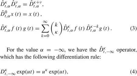
anduis a complex quantityu∈C.Forα=0,the differentiation operator.
It has been established that the differentiation operatoris more adequate to describe the forced response of our model[33].
Useofprovides the different results with respect to.It is important that this situation is more restrictive and can be considered similar to the use of the Fourier transform in nonhomogeneous differential linear equations:this case gives the part of the solution connected to the permanent response/perturbation.
3 Adomiandecom position method
The time-dependent canonical form of the equation in the Adomian decomposition method is[26,34,35]:

whereare linear residual,linear invertible,nonlinear operators,respectively.g(x)andx(t)are given and unknown functions,respectively.
The solution of Eq.(5)can be considered as:


Example1Consider the Lippincott potential:
The Lippincott potential is an intermolecular potential that has been considered in some researches[36,37].We considered the anharmonic elastic force originated from the potential.It can be written as:
wheredeis the equilibrium position in our model andE=According to Eq.(1),the equation of motion of a sphere for the Lippincott potential can be obtained and can be solved via the Adomian decomposition method(details are given in the “Appendix A”).Finally forμ=1,we have:

whereSLandNLare defined in Eqs.(A11)and(A12),respectively.Using the first and second derivation of Eq.(14)to time one can calculate the velocity and the acceleration of the movable electrode,respectively.
Example2Consider the Murrell–Mottram potential:
The intermolecular Murrell–Mottram potential is an example of cluster-type potentials,and consists of sums of effective two and three body interactions[38].The potential has been considered in many studies and is written as[39]:

whereDandbare the dissociation energy and the anharmonicity constant,respectively.
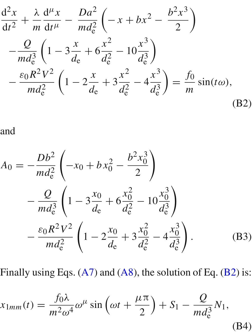
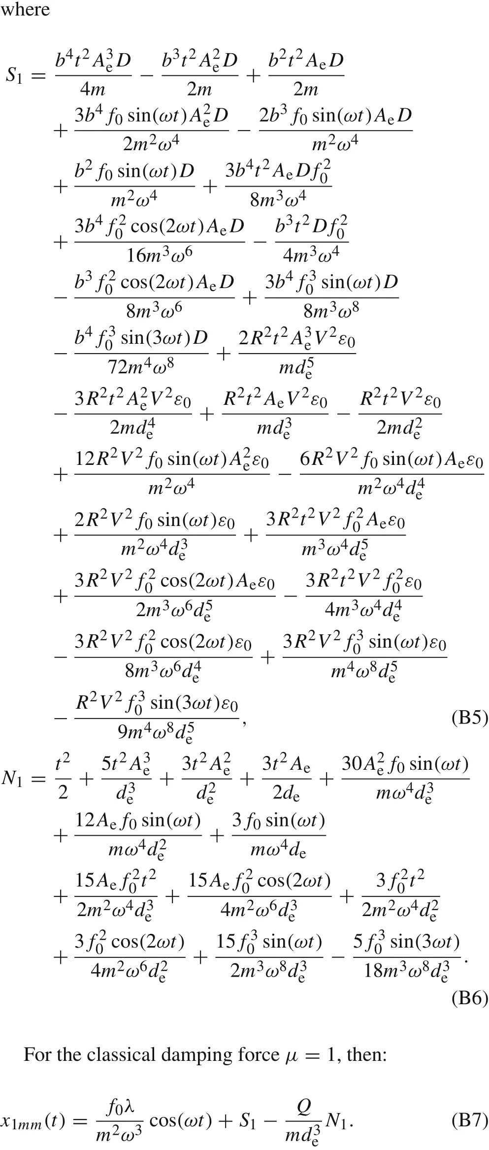
Starting from Eq.(1),applying Eq.(15)and via the Adomian method,x1mmforμ=1 is given by(see “Appendix B”for details):

whereS1andN1are defined as Eqs.(B5)and(B6),respectively.For both examples,equationA1=x1df(x0)/dx0can be used to obtainx2(t).
4 Effect o f order of expansions considering the Murrell–Mottram potential
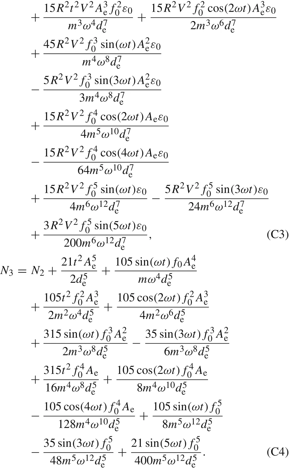
A proof of the convergence of the Adomian method was presented by Cherruault and Adomian[40].The goal of the present section is to answer this question:Does the order of expansion have any important role on the displacement of the movable electrode,its velocity and acceleration?We answered this question via obtaining the solution of the nonlinear equations with the Murrell–Mottram potential and comparing the results.We considered three cases including case1:order of expansions up to three,case2:order of expansions up to four,and case 3:order of expansions up to five.For case1,the obtained solution is Eq.(16).For case2,whenμ=1 we obtain:
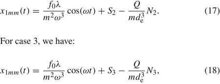
whereS2,N2,S3,andN3are given in “Appendix C”.
Via the first and second derivation of the replacement of the sphere to time(Eqs.(16)–(18)),we can calculate the velocity and the acceleration of the movable electrode,respectively.
5 Pu ll-in parameter
The pull-in parameterΔPI=xPI/deis the dimensionless variable which has a region between 0 and 1[41].It has been investigated in some models including the 1D lumped model,the linear superposition and nonlinear models[2].Their results indicated that the error of the pull-in parameters between the one-dimensional lumped model and the nonlinear beam model is large because the denominator of the electrostatic force is minimal when the electrostatic force is computed at the maximum deflection along the beam.In our model the changes in pull-in parameter according to the anharmonicity constant of the potential acting on the wire and equilibrium distance between the two electrodes were considered.ThenΔPIin this model including Murrell–Mottram potential is found as:

Table1 Pull-in parameter for different models

If the anharmonicity constant has been considered very small,the pull-in valueΔPIwill be equal to 1/3.Table 1 compares the parameter in our model with other models[2].
6 Results and discussions
In this work a one-dimensional actuator including the Casimir and electrostatic forces perturbed by an external force with fractional damping was modeled.The movable electrode was assumed to oscillate by an anharmonic elastic force originating from a Murrell–Mottram or Lippincott potential.The Adomian decomposition method was applied to solve the obtained equations.Also,the convergence of the Adomian decomposition method(ADM)in our model was investigated.The pull-in parameter was calculated and compared with other models.Our model can prepare some information for fabrication the nano-devices.
In order to put our results into perspective considering the Lippincott potential(LP),the parameters have been assumed asAe=0,de=10?7m,k2=10?5N/(m·s2),m=10?8kg,D=De=10?19J,ω=103s?1,λ=10?6kg·s·m?1,V=50V,R=10?9m,f0=10?9N,a=10?8m?1,andε0=8.85×10?12F·m?1.We plotted the displacement of the movable electrode from equilibrium position versus time in Fig.2a.This figure depicts that the competition among the acting forces causes the sphere to oscillate. In every region of time that the nonlinear Lippincott and fractional damping forces overcome the other forces,the sphere is ind>deregion,and whenever the electrostatic and Casimir forces overcome others,the sphere is found ind<deregion.In the initial times the effects of the nonlinear and fractional forces are more than others and then they decrease.The effects of the electrostatic and Casimir forces pull the sphere to come back toward the equilibrium position and then the displacement of the sphere will increase to a maximum ind<deregion.As the Fig.2a shows whentis near 0.0015,0.005,and 0.0075s the sphere is in equilibrium.The velocity of the sphere can be expressed via the first derivative of Eq.(14)to time.The curve of velocity versus time has been plotted in Fig.2b.The second derivative of Eq.(14)results in the acceleration of the movable electrode.Figure 2c indicates the curve of acceleration versus time.As Fig.2 shows,all functions oscillate with time.The mentioned competitions can be also seen in Fig.2b,c.In the initial times the velocity is toward the fixed electrode while the acceleration is against this direction.Equation(14)shows that increasing the mass of the sphere will decrease the oscillations and the displacement from equilibrium position.
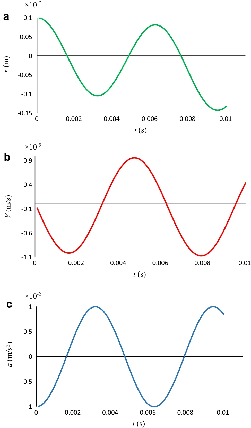
Fig.2 a Displacement,b velocity,and c acceleration from the equilibrium position of the sphere versus time considering the Lippincott potential.A e=0,d e=10?7m,k2=10?5N/(m·s2),m=10?8kg,D e=10?19 J,ω=103 s?1,λ=10?6 kg·s·m?1,V=50 V,R=10?9 m,f0=10?9N,a=10?8m?1,and ε0=8.85 × 10?12 F ·m?1
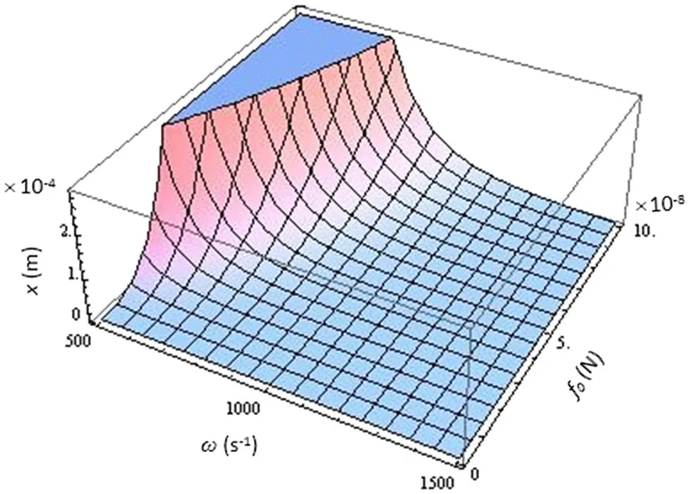
Fig.3 3D plot of displacement from the equilibrium position of the sphere as a function of frequency and amplitude considering the Lippincott potential.A e=0,d e=10?6m,k2=10?5 N/(m ·s2),m=10?9 kg,D e=10?19 J,t=10?4 s?1,λ =10?6 kg ·s·m?1,V=50V,R=10?8m,a=10?8m?1,and ε0=8.85 × 10?12 F ·m?1
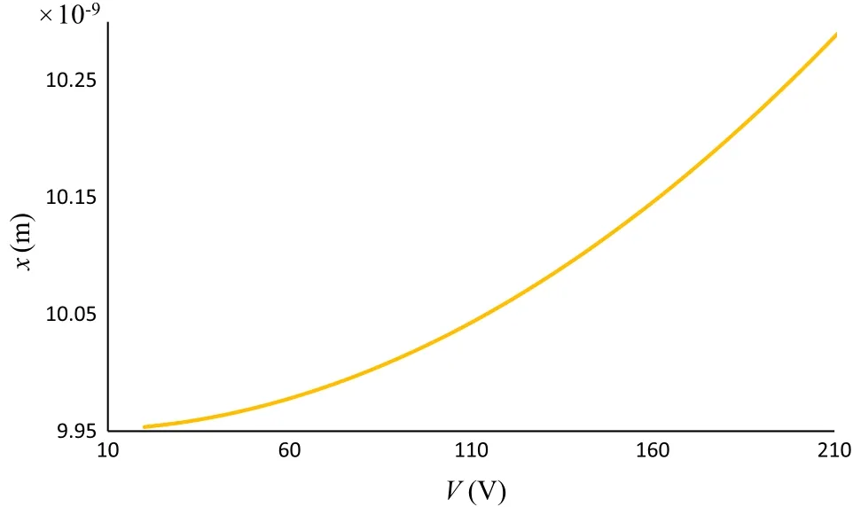
Fig.4 Displacements from the equilibrium position of the sphere as a function of voltage considering the Lippincott potential.A e=0,d e=10?6 m,m=10?9 kg,D e=10?19 J,t=10?4 s?1,k2=10?5 N/(m·s2),λ =10?6 kg·s·m?1,f0=10?9 N,R=10?8 m,ω =103 s?1,a=10?8m?1,and ε0=8.85 × 10?12 F ·m?1
The dependence of the displacement of the sphere on the frequency and the amplitude of the perturbing external force has been indicated in Fig.3.t=10?4has been assumed.As the Fig.3 depicts in a constant amplitude,increasing the frequency decreases the displacement ind>deregion and after aroundω=1200s?1it will be zero.However,the effect of the amplitude in a constant frequency is to increase the displacement of the movable electrode in thed>deregion.The incremental effect of the amplitude and the oscillatory effect of the frequency on the displacement was foreseeable according to the introduced perturbing external force.
In order to investigation of the effect of voltage on displacement,its curve has been plotted in Fig.4 when 20<V<240 andt=10?4.As Fig.4 shows there is a linear relation between voltage and displacement so that increasing the voltage increases the displacement of the sphere from the equilibrium position.Figure 5 indicates the displacement of the movable electrode as a function of the radius of the sphere and the equilibrium position.
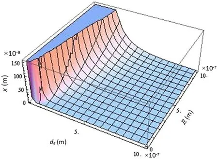
Fig.5 3D plot of displacement as a function of radius and equilibrium position considering the Lippincott potential.A e=0,m =10?9 kg,D e=10?19 J,t=10?4 s?1,λ =10?6 kg ·s·m?1,k2=10?5 N/(m ·s2),V =50V,f0=10?9 N,a=10?8m?1,and ε0=8.85×10?12 F·m?1
As it can be seen,increasing the radius increases the displacement in a constantdewhile increasing in the equilibrium position reduces the displacement whenRis constant ind>deregion.This is because of the competitive effects of the forces on the mass centre of system.
In order to discuss about the results considering the Murrell–Mottram potential,the variables were selected as those of the Lippincott potential.We plotted the displacement curve of the movable electrode from equilibrium position for case 1 versus time in Fig.6a.Competition among the forces acting on the sphere causes that at 0<t<0.003 the sphere approaches to the fixed electrode anddbe less thande.It shows that in this region the Casimir and electrostatic forces overcome the other forces.Then after a minimum,the effect of these forces decreases,and the effect of the forces originating from the Murrell–Mottram potential and fractional damping starts to increase.In 0.003<t<0.01 the general scheme of the curve is incremental.Although there is a minimum,but in all of this regiond>de.The velocity(v)of the sphere can be expressed with the first derivative of Eq.(16)to time.The curve of velocity versus time has been plotted in Fig.6b.The second derivative of Eq.(16)results in the acceleration(a)of the movable electrode.Figure6c indicates the curve of accelerate versus time.As the Fig.6 shows that all functions oscillate with time.The discussed competitions can also be seen in Fig.6b,c.In the initial times the velocity of the movable electrode is toward the fixed electrode,while the acceleration is in opposite direction to bring the movable electrode up.
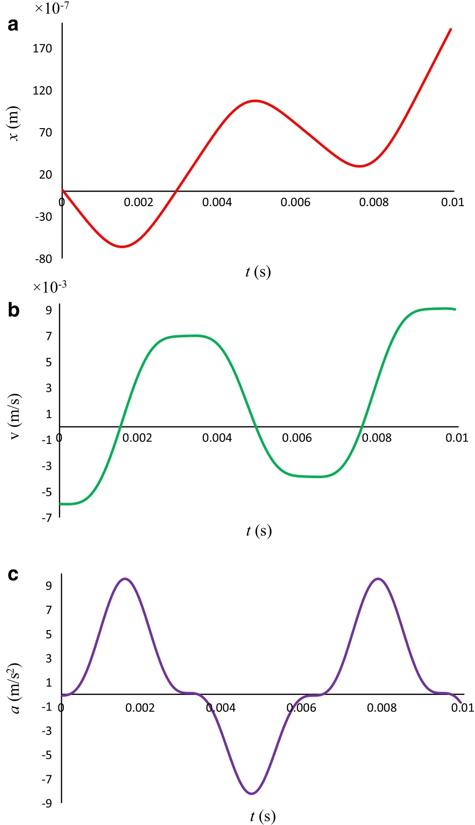
Fig.6 a Displacement,b velocity,and c acceleration from the equilibrium position of the sphere versus time for case 1 considering the Murrell–Mottram potential.A e=0,d e=10?6m,m=10?9 kg,D=10?19 J,ω =103 s?1,λ =10?8 kg ·s·m?1,V =50V,R=10?8m,f0=10?8 N,b=10?8m?1,and ε0=8.85×10?12 F·m?1
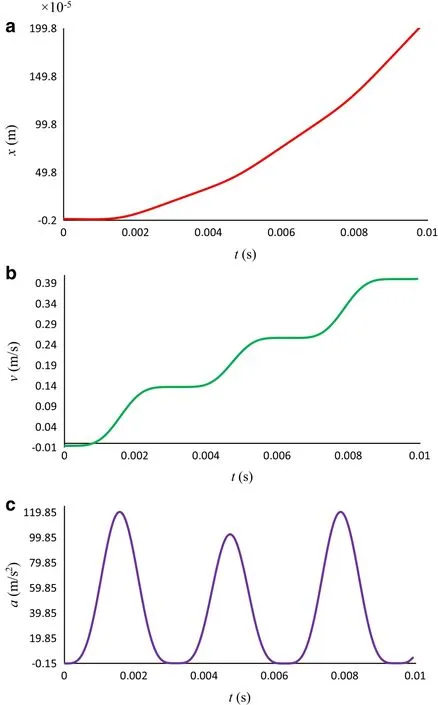
Fig.7 a Displacement,b velocity,and c acceleration from the equilibrium position of the sphere versus time for case 2 considering Murrell–Mottram potential.A e=0,d e=10?6m,m=10?9 kg,D=10?19 J,ω =103 s?1,λ =10?8 kg ·s·m?1,V =50V,R=10?8m,f0=10?8 N,b=10?8m?1,and ε0=8.85×10?12 F·m?1
For case 2,originating from Eq.(17),the curves of displacement,velocity and acceleration were plotted in Fig.7a–c.As Fig.7as hows,the displacement increases in the whole of the selected region of time andd>de.It shows for the even orders of expansion,the effect of the forces which bring the sphere up against the fixed electrode,is overcome in 0<t<0.01.The velocity and acceleration curves oscillate in the whole region.The velocity also increases,generally.For case 3,the curves of displacement,velocity and acceleration originating from Eq.(18)were plotted in Fig.8a–c.As Fig.8 depicts,the general behaviors are the same as when we considered case 1 although the quantities are different.The quantities of Eq.(18)are more,remarkably,but still the maximum and minimum occur in the same values of time.It is foreseen that the general behavior and the extremes of the curves in odd orders of expansion are the same but their values are different.It is true for even orders too.It is obvious that for the higher orders,the values are more.Equations(16)–(18)show that increasing the mass of the sphere will decrease the oscillations and the displacement from equilibrium position.
The general result considering both examples is that the termNiis independent of the nature of applied potential.It depends on external excitation force.It is the same term if the applied potentials have a same order of expansion.However,it will be different if the various orders of expansion are considered.
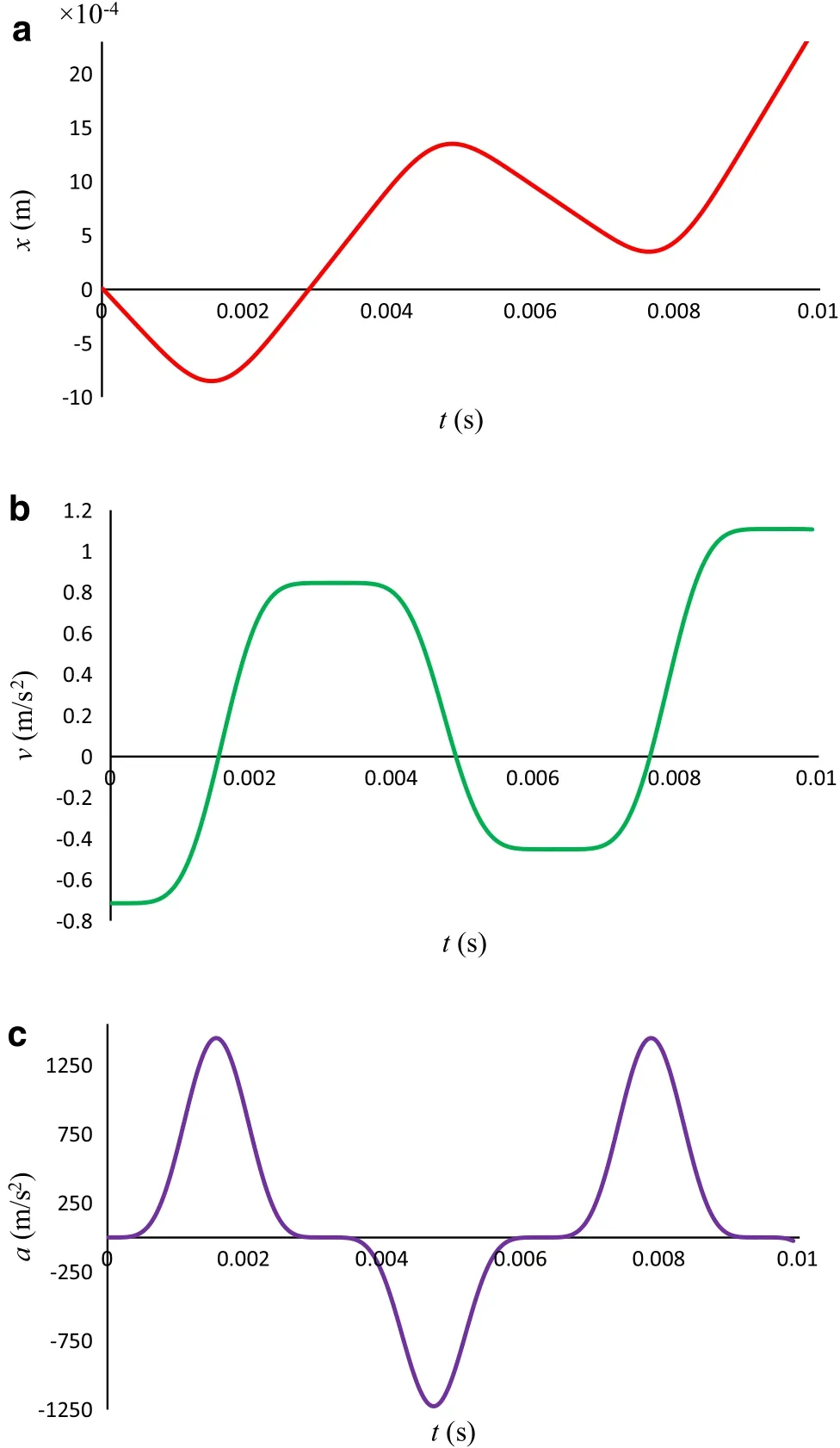
Fig.8 a Displacement,b velocity,and c acceleration,from the equilibrium position of the sphere versus time for case 3 considering the Murrell–Mottram potential.A e=0,d e=10?6m,m=10?9 kg,D=10?19 J,ω =103 s?1,λ =10?8 kg ·s·m?1,V =50V,R =10?8m,f0=10?8 N,b=10?8m?1,and ε0=8.85×10?12 F·m?1
The dependence of the displacement of the sphere on the frequency of the perturbing external force is shown in Fig.9a–c for cases 1 to 3,respectively.t=10?3has been assumed.As this figure indicates for the odd orders of expansion,the general behaviour of the displacements versus the frequency are the same but the values are different and for the higher orders,the values are more.Figure 9a,c show that the maximum of the displacement when 500<ω<1500 is in 500 s?1and with increasing inω,the displacement from equilibrium position decreases.For case 1 after aroundω=1000 s?1,the displacement is zero and constant.The zero point of displacement for case 3 occurs nearω=700 s?1.For both cases and all of the frequency region,d<de.As the Fig.9b shows,the behaviour of even orders of expansion is different.Again,the maximum of displacement is inω=500 s?1but the curve is in thed>deregion.Increasing the frequency decreases displacement and after aroundω=800 s?1it will be zero and constant.
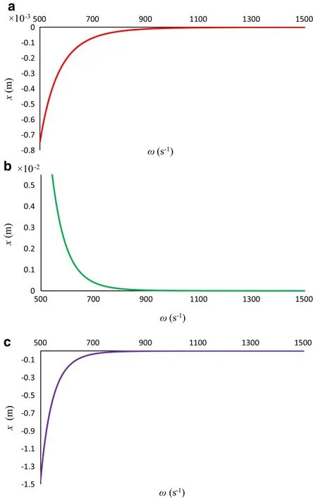
Fig.9 Displacements from the equilibrium position of the sphere as a function of frequency,a for case 1,b for case 2,and c for case 3 considering the Murrell–Mottram potential.A e=0,d e=10?6m,m=10?9 kg,D=10?19 J,t=10?3 s?1,λ =10?8 kg ·s.·m?1,V=50V,R=10?8m,f0=10?8 N,b=10?8m?1,and ε0=8.85×10?12F·m?1
The curves of displacement from equilibrium position versus voltage of the electrostatic force in 20<V<240 have been plotted in Fig.10a–c for Eqs.(16)–(18).t=10?3s andω=103s?1have been assumed.Here the behaviour of the odd orders are the same and different from those of the even orders of expansion.As Fig.10 shows increasing the voltage increases the displacement of the sphere.The values of case 3 are more,remarkably.In cases 1 and 3,the sphere is in thed<deregion;however,for case 2 it is ind>de.The values of displacement in this case are more than case 1 but less than case 3.
In another part of this work,the pull-in parameter has been calculated.The calculated pull-in parameter according to different models is different.These differences depend on boundary conditions which are assumed for computing the numerical integration in any are model that is not completely satisfied.To evaluate the dependence of pull-in parameter on the anharmonicity constant and the equilibrium position,a 3D plot of Eq.(19)is indicated in Fig.11.As this figure shows,the pull-in parameter changes from 0 to 0.33 along with changing inbfrom 10?6to 10?8anddefrom 10?6to 10?5.

Fig.10 Displacements from the equilibrium position of the sphere as a function of voltage,a for case 1,b for case 2,and c for case 3 considering the Murrell–Mottram potential.A e=0,d e=10?6 m,m=10?9 kg,D=10?19 J,t=10?3 s?1,λ =10?8 kg ·s·m?1,ω =103 s?1,R=10?8 m,f0=10?8 N,b=10?8 m?1,and ε0=8.85×10?12 F·m?1
Figure 12 shows the changes of pull-in parameter whende=10?6andb=10?8.As Fig.12a indicatesΔPIhas the maximum of its value whenb=10?8,that is 0.33,and along with increasing the value of the anharmonicity constant,the parameter decreases,monotonically.Therefore,the pull-in parameter has an inverse linear relation withbin the considered range.In the constant value ofb=10?8,Fig.12b depicts that the pull-in parameter has the constant value of 0.33 in all region ofdefrom 10?6to 10?5.
It is worth mentioning that all of the calculations were performed by making use of Mathematica 9 programs[42].
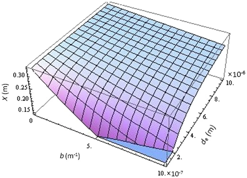
Fig.11 3D plot of pull-in parameter versus anharmonicity constant and equilibrium position of the sphere
The advantages of our model are:
(1)We solved the equations via the Adominade composition method.The advantage of the method is that it is not affected by errors associated with discretization because it does not require discretization of the variables.Also the Adomian method with conservation of the accuracy in numerical solution reduces the size of computational works.
(2)We considered the forces originating from the Murrell-Mottram potential and the Lippincott potential.The forces were interesting because they have not been used in the NEMS models up to now.Also,considering the nonlinear properties of the assumed forces,our model is a practical model for the real phenomena which include the nonlinear effects.
(3)We used the fractional damping operator because of considering the energy dissipation in our model.In this way our model is more useful in engineering applications.
7 Conclusion
Considering the one-dimensional oscillatory actuator model with fractional damping,the nonlinear behaviour of fractional differential equations has been investigated.The nonlinearity of the equations was due to anharmonic elastic force deriving from the Murrell–Mottram and Lippincott potentials.The solutions have been obtained with the aid of the Adomian’s decomposition method.The behaviour of displacement,velocity and acceleration were investigated.The different orders of expansions in nonlinear equations were considered in order to compare their effect on the results.The pull-in parameter has been calculated and compared with other models.Also the changes of the parameter versus the equilibrium position and anharmonicity constant were discussed.
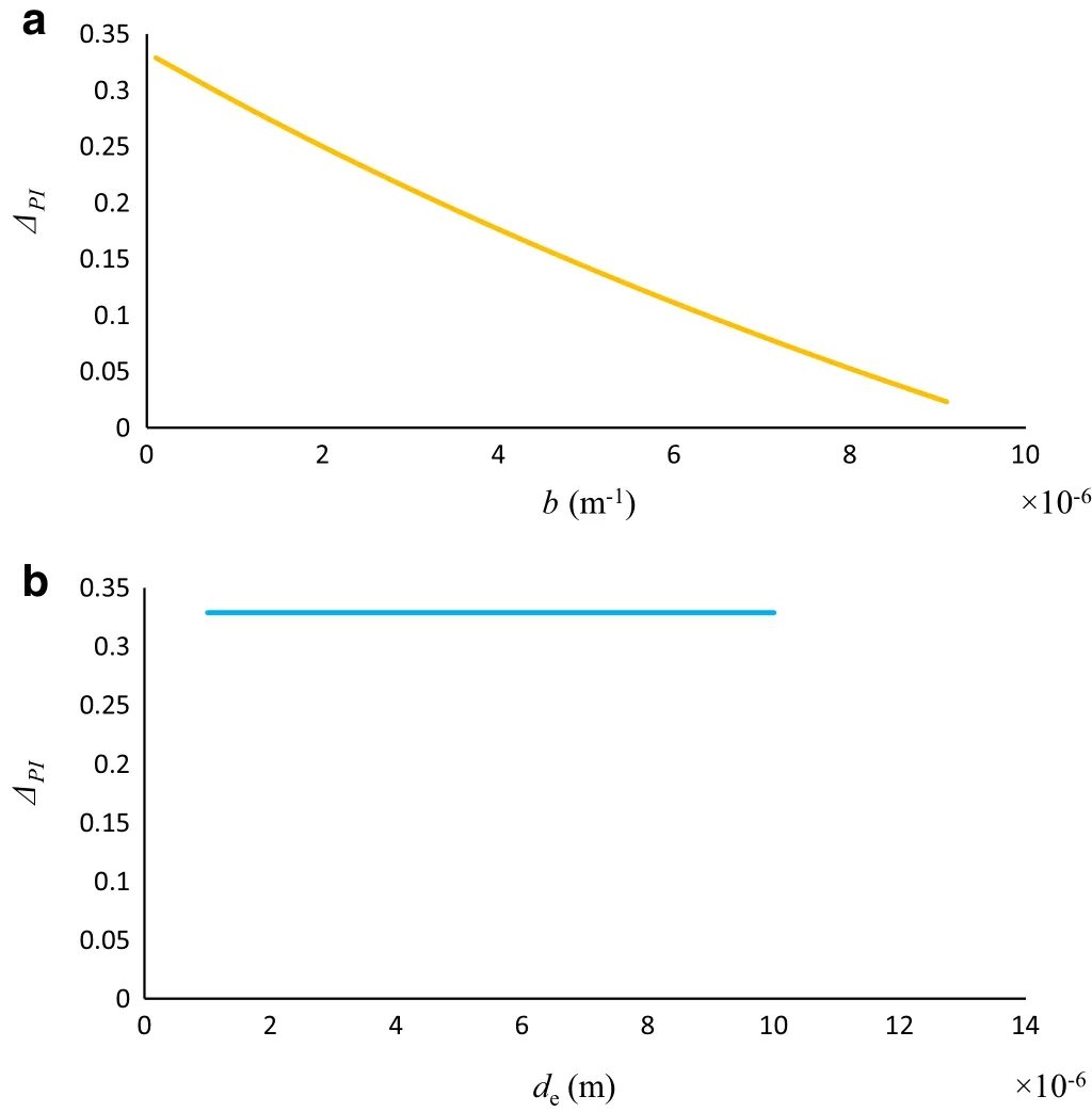
Fig.12 Pull-in parameter versus a anharmonicity constant when d e=10?6 m and versus b equilibrium position of the sphere when b=10?8m?1
Appendix A
According to Eq.(1),the equation of motion of a sphere is given by:
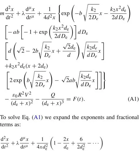
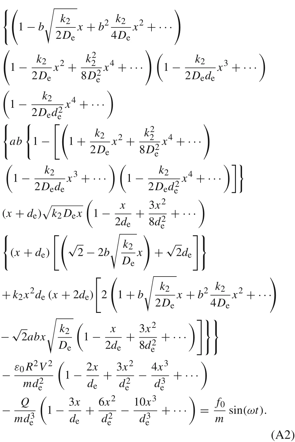
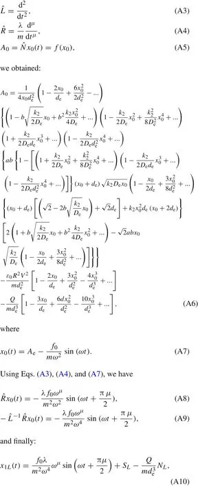
In Eq.(A2),we have considered the terms ofxup to third.Using the decomposition method and with the initial conditionsx(0)=Aeand˙x(0)=0,and


Appendix B

Using the decomposition method and the same initial conditions as “Appendix A”,and also considering the order of expansions up to three we obtained:
Appendix C


1.Zhang,W.M.,Yan,H.,Pemg,Z.K.,et al.:Electrostaticpull-in instability in MEMS/NEMS:a review.Sens.Actuators A Phys.214,187–218(2014)
2.Lin,W.H.,Zhao,Y.P.:Pull-in instability of micro-switch actuators:model review.Int.J.Nonlinear Sci.Numer.Simul.9,175–183(2008)
3.Duan,J.,Li,Z.,Liu,J.:Pull-in instability analyses for NEMS actuators with quartic shape approximation.Appl.Math.Mech.37,303–314(2016)
4.Dai,H.L.,Wang,L.:Surface effect on the pull-in instability of cantilevered nano-switches based on a full nonlinear model.Physica E Low Dimens.Syst.Nanostruct.73,141–147(2015)
5.Ma,J.B.,Jiang,L.,Asokanthan,S.F.:Influence of surface effects on the pull-in instability of NEMS electrostatic switches.Nanotechnology 21,505708–505717(2010)
6.Wang,K.F.,Wang,B.L.:Influence of surface energy on the nonlinear pull-in instability of nano-switches.Int.J.Nonlinear Mech.59,69–75(2014)
7.Kim,N.,Aluru,N.R.:Effect of intermolecular force on the static/dynamicbehaviour of M/NEM devices.Nanotechnology.25,485204–485216(2014)
8.Ramezani,A.,Alasty,A.,Akbari,J.:Closed-form solutions of the pull-in instability in nano-cantilevers under electrostatic and intermolecular forces.Int.J.Solids Struct.44,4925–4941(2007)
9.Moeenfard,H.,Ahmadian,M.T.:Analytical modeling of static behavior of electrostatically actuated nano/micromirrors considering van der Waals forces.Acta Mech.Sin.28,729–736(2012)
10.Lin,W.H.,Zhao,Y.P.:Influence of damping on the dynamical behavior of the electrostatic parallel-plate and torsional actuators with intermolecular forces.Sensors 7,3012–3026(2007)
11.Pritchard,R.H.,Terentjev,E.M.:Oscillations and damping in the fractional Maxwell materials.J.Rheol.61,187–203(2017)
12.Ghanbari,M.,Hossainpour,S.,Rezazadeh,G.:Studying thin film damping in a micro-beam resonator based on non-classical theories.Acta Mech.Sin.32,369–379(2016)
13.Casimir,H.B.G.:On the attraction between two perfectly conducting plates.Proc.Koninklijke Ned.Akad.Wet.51,793–796(1948)
14.Lin,W.H.,Zhao,Y.P.:Casimir effect on the pull-in parameters of nanometer switches.Microsyst.Technol.11,80–85(2005)
15.Serry,F.M.,Walliser,D.,Maclay,G.J.:The role of the Casimir effect in the static deflection and stiction of membrane strips in Microelectro mechanical systems MEMS.J.Appl.Phys.84,2501–2506(1998)
16.Ding,J.N.,Wen,S.Z.,Meng,Y.G.:Theoretical study of the sticking of a membrane strip in MEMS under the Casimir effect.J.Micromech.Microeng.11,202–208(2001)
17.Buks,E.,Roukes,M.:Stiction,adhesion energy,and the Casimir effect in micromechanical systems.Phys.Rev.B 63,033402-1–033402-4(2001)
18.Lin,W.H.,Zhao,Y.P.:Nonlinear behavior for nanoscale electrostatic actuators with Casimir force Chaos.Solitons Fract.23,1777–1785(2005)
19.Bordag,M.,Mohideen,U.,Mostepanenko,V.M.:New developments in the Casimir effect.Phys.Rep.353,1–205(2001)
20.Guo,J.G.,Zhao,Y.P.:Influence of vander Waals and Casimir forces on electrostatic torsional actuators.J.Microelectromech.Syst.13,1027–1035(2004)
21.Mojahedi,M.,Ahmadian,M.T.,Firoozbakhsh,K.:The oscillatory behavior,static and dynamic analyses of a micro/nano gyroscope considering geometric nonlinearities and intermolecular forces.Acta Mech.Sin.29,851–863(2013)
22.Draganescu,G.E.,Bereteu,L.,Ercuta,A.,et al.:Anharmonic vibrations of a nano-sized oscillator with fractional damping.Commun.Nonlinear Sci.Numer.Simul.15,922–926(2010)
23.Wang,K.F.,Wang,B.L.:A general model for nano-cantilever switches with consideration of surface effects and nonlinear curvature.Physica E Low Dimens.Syst.Nanostruct.66,197–208(2015)
24.Zhang,Y.,Liu,Y.,Murphy,K.D.:Nonlinear dynamic response of beam and its application in nanomechanical resonator.Acta Mech.Sin.28,190–200(2012)
25.Mansoori Kermani,M.,Dehestani,M.:Solving thenonlinearequations for one-dimensional nano-sized model including Rydberg and Varshni potentials and Casimir force using the decomposition method.Appl.Math.Model.37,3399–3406(2013)
26.Adomian,G.A.:Review of decomposition method in applied mathematics.J.Math.Anal.Appl.138,501–544(1988)
27.Kuang,J.H.,Chen,C.J.:Adomian decomposition method used for solving nonlinear pull-in behavior in electrostatic micro-actuators.Math.Comput.Model.41,1479–1491(2005)
28.Chen,W.,Lu,Z.:An algorithm for Adomian decomposition method.Appl.Math.Comput.159,221–235(2004)
29.Wazwaz,A.M.:A comparison between Adomian decomposition method and Taylor series method in the series solution.Appl.Math.Comput.97,37–44(1998)
30.Abbasbandy,S.:A numerical solution of Blasius equation by Adomian’s decomposition method and comparison with homotopy perturbation method.Chaos Solition.Fract.31,257–260(2007)
31.Lavoie,J.L.,Osler,T.J.,Tremblay,R.:Fractional derivatives and special functions.SIAM Rev.18,240–268(1976)
32.Abramowits,M.,Stegun,I.A.:Handbook of Mathematical Functions with Formulas,Graphs,and Mathematical Tables.National Bureau of Standards,Washington,DC(1964)
33.Gómez-Aguilar,J.F.,Yépez-Martínez,H.,Calderón-Ramón,C.,et al.:Modeling of a Mass–Spring–Damper system by fractional derivatives with and without a singular kernel.Entropy 17,6289–6303(2015)
34.Basto,M.,Semiao,V.,Calheiros,F.L.:Numerical study of modified Adomian’s method applied to Burgers equation.J.Comput.Appl.Math.206,927–949(2007)
35.Ramana,P.V.,Raghu Prasad,B.K.:Modified adomian decomposition method for Van der Pol equations.Int.J.Nonlinear Mech.65,121–132(2014)
36.Lippincott,E.R.,Steele,D.,Caldwell,P.:General relation between potential energy and internuclear distance for diatomic molecules.III.Excited states.J.Chem.Phys.35,123–141(1961)
37.Schlegel,H.B.,Wolfe,S.,Bernardi,F.:Abinitio computation of force constants.II.The estimation of dissociation energies from abinitio SCF calculations.Can.J.Chem.53,3599–3601(1975)
38.Lim,T.C.:Relationship between Morse and Murrell-Mottram potentials at long range.J.Math.Chem.36,139–145(2004)
39.Lim,T.C.:Relationship between the 2-body energy of the Biswas-Hamann and the Murrell-Mottram potential functions.Z.Naturforsch.59a,116–118(2004)
40.Cherruault,Y.,Adomian,G.:Decomposition method:a new proof of convergence.Math.Comput.Model.18,103–106(1993)
41.Lin,W.H.,Zhao,Y.P.:Dynamics behavior of nanoscale electrostatic actuators.Chin.Phys.Lett.20,2070–2073(2003)
42.Wolfram Research,Inc.Mathematica,v.9;Wolfram Research,Inc.:1988–2015
- Acta Mechanica Sinica的其它文章
- Instability waves and low-frequency noise radiation in the subsonic chevron jet
- Density enhancement mechanism of upwind schemes for low Mach number flows
- Hydrodynamic studies on two wiggling hydrofoils in an oblique arrangement
- The spanwise spectra in wall-bounded turbulence
- The dimension split element-free Galerkin method for three-dimensional potential problems
- Zero group velocity longitudinal modes in an isotropic cylinder

