Partition method and experimental validation for impact dynamics of flexible multibody system
J.Y.Wang·Z.Y.Liu·J.Z.Hong
1 Introduction
The accurate and efficient modeling of contact/impact is one of the main difficulties in many engineering applications.The numerical approaches that are used widely in contact/impact analysis can be divided into two categories:approaches based on computational solid mechanics(CSM),see Refs.[1–3],and approaches based on multibody system dynamics(MBS),see Refs.[4–7].
In CSM,the finite element method(FEM)is most widely used to model the deformations,and usually the node-tosegment approach is used to discretize the contact surfaces.It is of major interest to predict the strain and stress field in the deformable bodies com ing into contact.It is well suited for particularly high accuracy needs,yet requires very high computational effort.
Approaches based on MBS provide a more efficient yet less accurate analysis of the contact/impact problems.These approaches emphasize capturing the effect of impact on the overall motion of the system for long simulation time.Usually,the floating reference frame formulation[8,9]is used to separate the overall motion into the rigid motion of the reference frame and a linear elastic deformation with respect to the reference frame.In order to gain computational effi-ciency,formulations based on the modal superposition and substructure methods have been used to reduce the number of degrees of freedom(DOFs),and various modal reduction techniques exist[10].For the modeling of contact,some simplifying assumptions are usually made in these approaches:the contact interface is represented by two coincident points and a local reference frame rather than a time-varying area,or the contact force is modeled as a Hertz force element rather than distributed forces.
We would like to bridge the gap between approaches based on CSM,which can acquire results of high accuracy yet require excessively long computation times,and approaches based on MBS,which cannot provide accurate local deformation information yet acquire considerably less computational burden.We thus start here with a survey of different approaches toward the goal of accuracy vs.efficiency trade-offs for contact/impact analysis in multibody system.
Considering a low velocity impact,only the local region of the flexible body immediately involved in the impact is subject to plastic or finite deformation.Based on this assumption,some methods that maintain accuracy in the local impact region yet reduce computational burden to a manageable level have been developed.The work of Benson and Hallquist[11]implemented a simple rigid body algorithm into DYNA3D.The mesh outside the impact region is replaced with a rigid body model to reduce the cost of the analysis with only a small loss in accuracy.Also,Ambrosio et al.[12]derived the equations of motion of the partially rigid- flexible body model and proposed the methodology for co-simulation of multibody and finite element codes.Furthermore,Lankarani and Nikravesh[13]used a multibody model of the occupant with a nonlinear FEM model of the lumbarspine for the crashdynamic simulation.In Kim et al.’s work[14]on contact problems of two flexible multibody systems,the components under going direct contact are model led using the FEM that incorporates large rigid body displacement,while the rest of the system is handled through the usual flexible multibody formulation.The simulation strategy presented by Seifried et al.[15]and Dong et al.[16]pursues a different approach.Different models of the flexible bodies are implemented in flight and impact phase.The float frame of reference formulation is used in the flight phase and FEM is used in the impact phase.
In this paper,the partition method is presented for the simulation of multibody system with impact.The non-impact region is modelled using the modal reduction approach to reduce the DOFs.The FEM is employed for modelling the nonlinear and plastic deformation in the local impact region.With this method,the computational efficiency of the whole system and the computational accuracy in the local impact region are both increased.
For the experimental investigations of impact problems,the main difficulty is that the impact duration is very short and the frequencies of impact responses are extremely high.Early experimental investigation mainly focused on transient strain response,in which the measurement instruments are mainly strain gauges[17].Accelerometers were also used in some impact experiments to measure points not located close to the impacts[18,19].With the advance of laser techniques,some impact experiments were conducted using laser-Doppler vibrometers(LDVs);however,these are mainly for one-dimensional rod impact or two-dimensional planar impact problems[15,16].
A three-dimensional impact of a hemispherical-tip rod on a square plate is designed and performed to validate the simulation results using the partition method.The rodplate impact problems have been investigated by several researchers using either analytical method[20,21]or FEM[22,23],but few of them are validated experimentally.In this experiment strain gauges and LDVs are employed to measure the high-frequency impact responses.Both FEM and the partition method are used to simulate the experimental case,and a principle for how to partition the contact bodies is proposed.The results show that the partition method is an effective formulation considering both accuracy and efficiency.Moreover,the partition method is applied to solve a more complicated impact problem of a crank slider mechanism,which is a typical flexible multibody system.
2 Partition method
In multibody dynamics with contact/impact,the rigidmotion of a flexible body is described by a floating reference frame,and the deformation is modeled by relative deformation coordinates.This section provides the derivation of the partition method for contact/impact problem in a multibody system,including the kinematic description and equations of motion.
2.1 Equations of motion using FEM
As shown in Fig.1,a deformable bodyBiis discretized by lumped mass FEM;therefore,the mass of body is distributed to each finite element node.The inertial reference frame is represented byer,and the floating reference frame attached to the body is denoted byeb.The position vector ofebwith respect toeris denoted asr.An arbitrary node positionrPof flexible bodyBiis defined by(ignore the body marki)

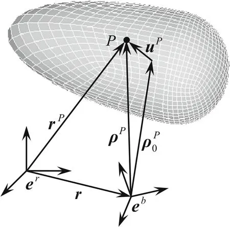
Fig.1 Kinematics of a flexible body using FEM
whererepresents the position of nodePin inertia frame,is the initial position,is the displacement in the floating frame,andAis the transformation matrix from the floating frame to the inertial frame.Equation(1)follows the notation(?)′,meaning that the quantity(?)is expressed in the floating frame.
Deriving Eq.(1)with respect to time yields the nodal absolute velocity,and deriving Eq.(1)twice results in the absolute acceleration:

whererepresents the angular velocity of the floating frame,and
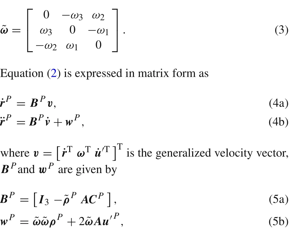
where the matrixCPis a Boolean matrix,leading to
Applying the principle of virtual power for the whole body,the equations of motion can be written as

wherefPis the nodal external force vector,CFandKFare the damping matrix and stiffness matrix assembled by FEM.
Substituting Eq.(3)into Eq.(6)yields:
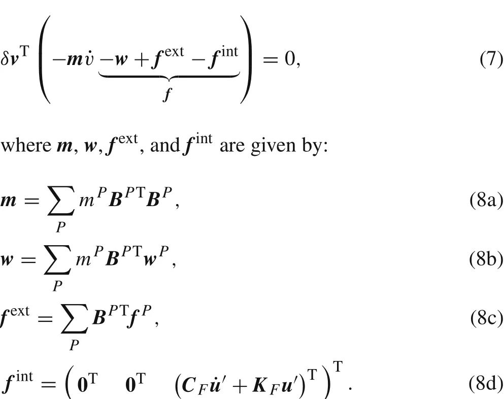
For a single flexible body,the coordinates are independent,Eq.(7)can be written as

For the system containingnbodies connected by kinematic joints,if the joint constraints aregJ(p)=0,pis generalized displacement vector,the equations of motion can be written as

whereis matrix leading torepresents the corresponding Lagrange multipliers.
2.2 Equations of motion using partition method
As shown in Fig.2,the contact body is decomposed into two parts,namely,the non-impact region I and the impact region II.
The deformation coordinate can be written as

wheredescribes the rigid body motion.

Fig.2 Partition of a flexible body using partition method
In order to reduce the system DOFs,the nodal coordinates in non-impact region I are reduced by a small number of main modes:

whereΦis the modal matrix,comprising the eigenmodes of the finite element structure andais the modal coordinate,which has much fewer degrees than that of nodal coordinateu.The eigenvaluesωiand the associated eigenmodes?iare derived from solving the eigenvalue problemis the mass matrix assembled in FEM.The modal matrix of non-impact regionΦIis selected from the entire modal matrix by node number.
Substituting Eq.(13)into Eq.(12),the generalized velocity becomes:

3 Modeling of contact force
For contact/impact dynamics of a discretized elastic body,two typical methods are usually presented to model the contact force:penalty method[1,15,24,25]and Lagrangian method[1,16,26,27].In the penalty method,the contact force is defined by a force function of local penetration at the contact point,because the non-penetration constraint is not precisely satisfied during the contact process,the accuracy of numerical simulation depends on the choice of the coefficient of contact stiffness.In contrast,the Lagrangian method for contact modeling,where constraint equations are appended to dynamic equations to be solved together,reflects the non penetration condition without manually defined parameters.In this section,the contact constraint equation is derived using Lagrangian method.
In computational contact mechanics,mostly the node-tosegment approach is used to discretize the contact surfaces,as shown in Fig.3.A node-to-segment element for the two colliding bodies is defined by the four nodesM1–M4on the master body and by the penetrating nodeSon the slave body.The other contact pointMon the master surface can be identified according to the closest point projection[2].
The vector of contact gap is given as

wherenis the normal vector of the master segment at the pointM.No impact occurs whenindicates an impact andindicates an non-physical penetration.
When contact occurs,according to the non-penetration condition in the contact point,the locking of the free motion in a normal direction is described by the following constraint equation on position level:

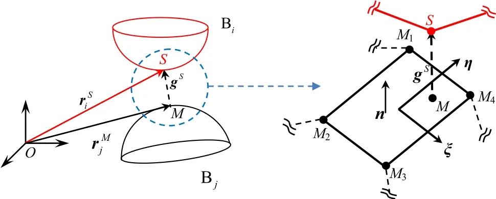
Fig.3 A node-to-segment contact pair
Deriving Eq.(21)yields the constraint equation on velocity level:

Ais on the tangent plane,the second term in Eq.(22)disappears.Deriving Eq.(22)yields the constraint equation on acceleration level:

Considering a normal contact,the relative velocity of the contact pair in the tangential direction tends to be zero,thus the second term in Eq.(23)can also be ignored.Substituting Eq.(19)into Eq.(23),we obtain:
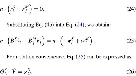
If there aremcontact pairs,the system contact constraint equations can be assembled as
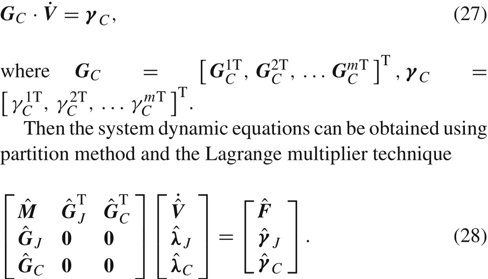
It is to be noted that Eq.(28)is an ODE;therefore,we can choose an arbitrary numerical integration approach.Here the explicit central difference method is applied.
The time integration can be written in the following form for a typical time steph:

4 Experimental setup
A schematic diagram of the impact experiment is shown in Fig.4,and an overview of the experimental setup is shown in Fig.5.A cylindrical steel rod with hemispherical tip is used to strike an alum inum plate.The two colliding bodies are suspended by two sets of thin wires in a“V”shape at two locations and are positioned horizontally by means of a spirit level.The rod just contacts the plate’s center and the rod’s axis is vertical to the plate’s surface when in equilibrium position.The plate remains still until a collision occurs.To ensure the impact point is at the center of the plate,a pencil is used to mark the accurate location,the rod head is painted with red ink,and then adjustments are performed until an imprint is produced exactly at the marked point of the plate.After impact the imprint is also checked and the experimental data is adopted only when the imprint is at the center.
The rod is set free from a specified height and impacts the plate at a velocity of about 0.596 m/s measured by the LDV.To determine the time of collision,we connect the two bodies to a direct current source,the current signal comes out in the contact process.For the investigated duration of 5 ms,the motion of both bodies can be considered as a free horizontal motion approximately.
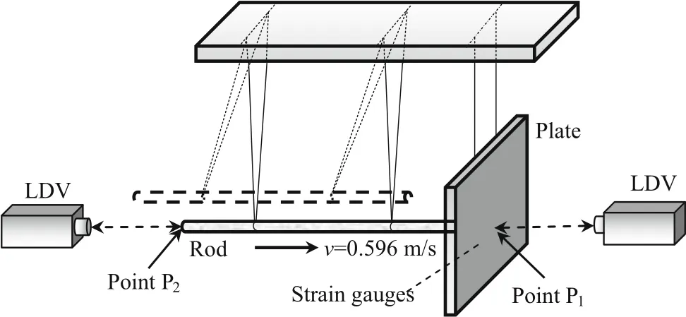
Fig.4 Schematic diagram of the rod-plate impact experiment
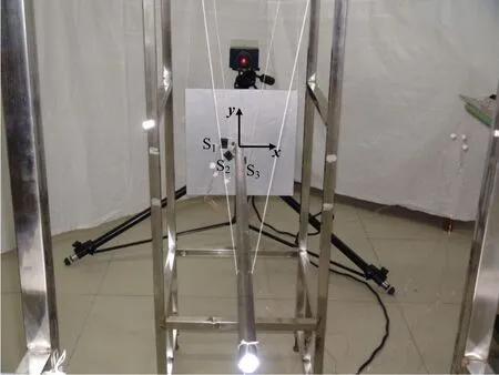
Fig.5 Overview of the experimental setup

Table 1 Geometrical and material parameters

Fig.6 Comparisons between experiment and FEM simulation.a Velocity of point P1.b Velocity of point P2
The strains are measured with strain gauges.As shown in Fig.5,three gauges are bonded to the contact surface of the plate in three directions 15 mm away from the center point,the strain gauge S1is located in thex-direction,the strain gauge S3is located in they-direction,the strain gauge S2has a 45°angle with both S1and S3.The used signal amplifier is of type YE3817c made by Sinocera Piezotronics,Inc.In the measurement the supplied constant voltage is set to 6 V and the amplifier gain is set to 500.
For the measurement of velocities,two laser-doppler vibrometers of type PSV-300F,made by Polytec GmbH are used.The vibrometer utilizes an interferometric technique to measure vibrational signals.The measurement range of velocity is±10 m/s,and the resolution reaches 10?6m/s.The back point of the rod and the center point of the plate are measured in the normal impact experiment.
The material and geometrical parameters of the two colliding bodies are tabulated in Table 1.
5 Simulation and experimental results
5.1 Comparison between FEM simulation and experiment
For numerical simulation using FEM,the commercial software ANSYS is used here.The finite element type is an 8-node hexahedral element.The spatial discretization is an essential factor.In impact dynamics,the mesh of the main part should be small enough to get an accurate representation of high frequency wave propagation.For the discretization of the local impact region,additional considerations are required.To represent sufficiently the deformation and stress distribution in the impact region,the impact region must be discretized in a much smaller size than the element length required for the wave propagation.
In the rod-plate impact case,the mesh size is gradually reduced until the simulation reaches convergence.The element length of main part is about 5 mm and that of the local region is less than 0.2 mm,and the total node amount is 95218.Comparisons between experiment and simulation using FEM are shown in Figs.6 and 7.Figure 6 shows the comparisons of velocities of the two measured points.Figure 7a shows the experiment data of three strain gauges and they agree with each other well because they are bonded at the same distance from the center.It also verifies that the contact point is the center of the plate.Take the strain gauge S2as an example to compare the experimental strain with the simulated strain,as shown in Fig.7b.The observation of the comparisons indicates that the FEM approach predicts the measured results very well when the spatial discretization is conducted appropriately.
5.2 Comparison between FEM and partition method
As shown in Sect.5.1,for a correct evaluation of the impact process,the FEM leads to an inefficient numerical implementation due to the large number of DOFs.In this section,the partition method will be used to reduce the system DOFs.The partition method is implemented in the MATLAB.
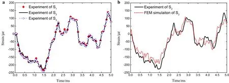
Fig.7 Strain values.a Experiment data of three strain gauges.b Comparison between Experiment and FEM simulation
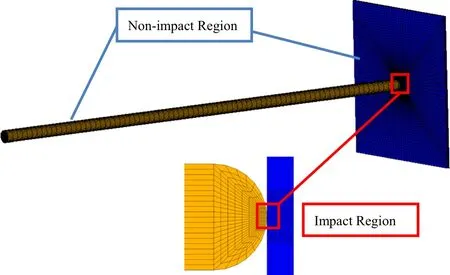
Fig.8 Partition of the impact bodies
The core idea of partition method is to use different coordinates to describe the deformations of different regions.As shown in Fig.8,the contact bodies are divided into two regions,the impact region is described by nodal coordinates and the non-impact region is defined using modal coordinates.
For the partition method,a very important problem is how to divide the contact bodies to ensure the accuracy of the simulation.That is to say,how many nodes should be used to describe the impact region,and how many orders of modes should be applied to describe the non-impact region?In the following,the principle for the partition scheme of the contact bodies will be given.
In order to determine the size of impact region,the maximum contact radius should be estimated beforehand.Here we use the Hertz contact law to simulate the impact case firstly.It predicts a rough maximum force of 800 N.From this the contact radiusrccan be calculated by the Hertz law:
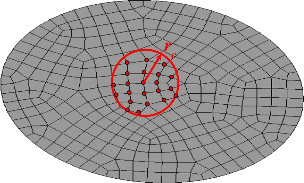
Fig.9 Maximum contact area
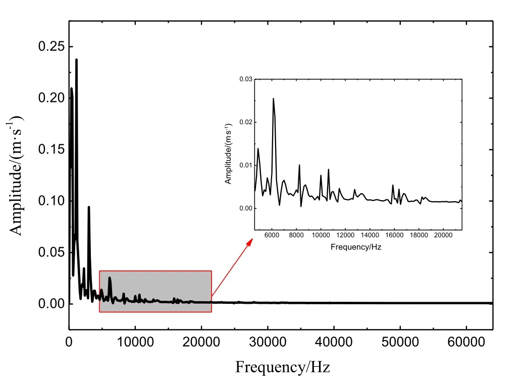
Fig.10 Amplitude-frequency response of velocity of point P1

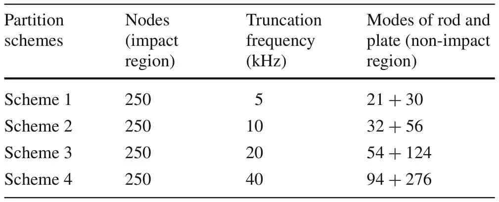
Table 2 Partition schemes of the contact bodies

Table 3 Comparison of efficiency between FEM and partition method
wherePis the contact force,Ris the curvature radius of the contact surface,in this caseR1=10 mm,R2=∞.
As shown in Fig.9,the red points in the circle belong to the impact region.In this rod-plate impact case,the impact region consists of 250 nodes in total.
Since impacts are high-frequency phenomena, it is not sufficientto retain only the lower order modes for the non-impact region.The modal truncation frequency should be determined by the measurement.Here we perform a fast Fourier transform(FFT)of the velocity response of the impact point P1,as shown in Fig.10.It can be seen that the frequency mainly concentrates in the range from 0 to 10 kHz,and the highest frequency of velocity response is up to 20 kHz.
We set the truncation frequency as 5,10,20,40 kHz,respectively,then we have four partition schemes as listed in Table 2.The results of the four partition schemes using partition method are compared with the result using FEM,as shown in Fig.11.It is shown that only keeping lower order modes leads to a large deviation.As the modes in nonimpact region increase,the result becomes more accurate.When the truncation frequency reaches 40 kHz,the result of partition method agrees very well with the result of FEM.It means that in the impact process very high order modes of the contact bodies are excited.In order to ensure the simulation accuracy,the modal truncation frequency should be about two times the highest frequency of measured signal.If there is no measurement data,the frequency up to 50–100 kHz have to be included in the reduction in impact dynamics,as presented by Seifried et al.[15].
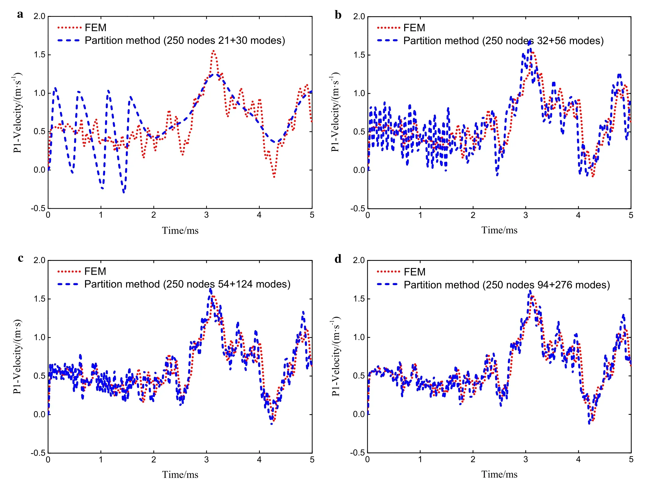
Fig.11 Comparisons between FEM and partition method.a Partition scheme 1.b Partition scheme 2.c Partition scheme 3.d Partition scheme 4

Fig.12 Impact of a crank slider mechanism

Table 4 Geometrical and material parameters
The comparison of efficiency between FEM and partition method is listed in Table 3.In this impact case,the partition method uses 250 nodes and 276+94=370 modes instead of 95218 nodes in FEM,the DOFs of the system is highly reduced and the computational scale is correspondingly reduced.When using the same numerical integration algorithm,the CPU time of FEM is about20h while the partition method needs only 0.973h.This shows that the partition method greatly improves the simulation efficiency.
6 Impact of a crank slider mechanism
The impact between a crank slider mechanism and a block is considered,as shown in Fig.12.The crank slider mechanism is composed of a rigid crank B1, flexible link B2,and two impact blocks B3,and B4.The rigid crank B1is homogeneous and has a length of 150 mm,a mass of 0.234 kg.The link B2has a rectangle cross-section.The block B3and B4are cylinders with spherical heads.The material and geometrical parameters of flexible bodies are listed in Table 4.All the flexible bodies are meshed with 8-node hexahedral element.
The crank B1is driven with a constant angular velocityω=10π rad/s,the initial angleθ=0°.The end of block B4is connected to a spring-damper with stiffness coefficientk=1×10⁵N/m and damping coefficientc=1×10³N·s/m.All frictions are ignored.A rotation cycle of0.2 sis simulated and the block B3will impact the block B4at some moment during the period.
The link B2is modeled using a 20 orders of modal coordinates,and the finite element model of B3and B4contains 9478 nodes.The presented partition method is applied to reduce the DOFs of B3and B4.The impact region consists of 150 nodes.In the reduction of the non-impact region,the modal truncation frequency is set as 100 kHz to guarantee the accuracy,and the modal orders of B3and B4are 15 and 12 respectively.Therefore,we replace 9478 nodes with 27 modes and150nodes.The number of basic variables is highly reduced and the computational burden is correspondingly reduced.
Figure 13 shows the contact force between B3and B4.It can be seen that the contact force undergoes a sharp jump at the impact moment and then gradually comes into the contact state. Figure 14 shows that the motion torque at the origin has a large peak during the contact and high frequency response is activated after impact.Figure 15 shows the velocity of the center point of B2,and obviously high frequency vibration is also excited due to the impact.
7 Conclusion
In this paper partition method for the description of multibody system with impacts is presented.With this method,the contact bodies are divided into two regions called impact region and non-impact region.The FEM is employed for modelling the nonlinear deformation and high stress in the local impact region.The non-impact region is model led using the modal reduction approach to raise the solving efficiency.Partition method bridges the gap between approaches based on CSM,which can acquire results of high accuracy yet require excessively long computation times,and approaches based on MBS,which can not provide accurate local deformation information yet acquire considerably less computational burden.

Fig.13 Contact force between B3 and B4
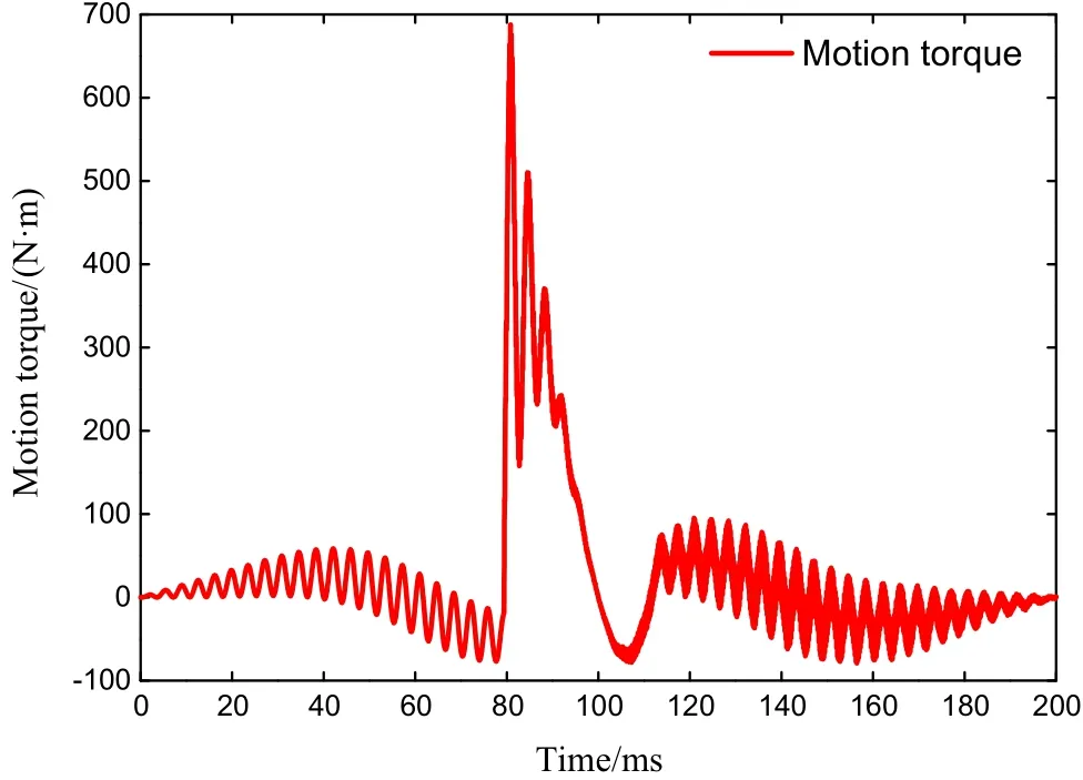
Fig.14 Motion torque at the origin
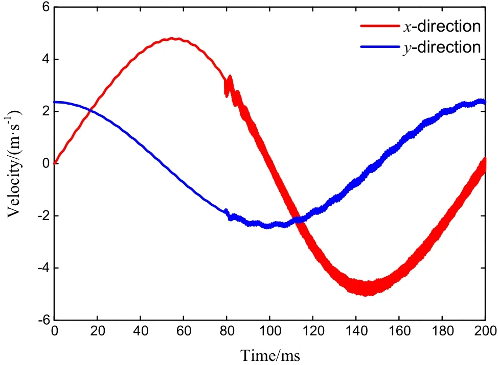
Fig.15 Velocity of the center point of B2
For validation of the presented method,a three-dimensional rod-plate impact experiment is performed with LDVs and straingauges.First,the FEM simulation results are compared with the experimental results,and they are in good agreement.Then,the results of partition method using different partition schemes are compared with the FEM results.The principle for how to partition the contact bodies is proposed:for the impact region,the analytical method is used to predict the maximum contact radius;for the non-impact region,the modal truncation frequency should be about twice of the highest frequency of measured signal.It is shown that the partition method can effectively reduce the computational scale and improve the computational efficiency.At last,the partition method is applied to solve a more complicated impact problem of a crank slider mechanism, which is a typical flexible multibody system.
AcknowledgementsThe project was supported by the National Natural Science Foundation of China(Grants 11772188,11132007).
1.W riggers,P.:Computational Contact Mechanics.Springer,Berlin(2006)
2.Laursen,T.A.:Computational Contact and Impact Mechanics:Fundamentals of Modeling Inter facial Phenomena in Nonlinear Finite Element Analysis.Springer,Berlin(2002)
3.Nsiampa,N.,Ponthot,J.P.,Noels,L.:Comparative study of numerical explicit schemes for impact problems.Int.J.Impact Eng.35,1688–1694(2008)
4.Wang,J.,Liu,C.S.,Zhao,Z.:Non-smooth dynamics of a 3D rigid body on a vibrating plate.Multibody Syst.Dyn.32,217–239(2014)
5.Machado,M.,Moreira,P.,Flores,P.,et al.:Compliant contact force models in multibody dynamics:evolution of the Hertz contact theory.Mech.Mach.Theory 53,99–121(2012)
6.Tian,Q.,Zhang,Y.,Chen,L.,et al.:Dynamics of spatial flexible multibody systems with clearance and lubricated spherical joints.Comput.Struct.87,913–929(2009)
7.Choi,J.,Han,S.R.,Chang,W.K.,et al.:An efficient and robust contact algorithm for a compliant contact force model between bodies of complex geometry.Multibody Syst.Dyn.23,99–120(2010)
8.Shabana,A.A.:Dynamics of Multibody Systems.Cambridge University Press,New York(2005)
9.Bauchau,O.A.:Flexible Multibody Dynamics.Springer,Netherlands(2011)
10.Sherif,K.,Witteveen,W.,Mayrhofer,K.:Quasi-static consideration of high-frequency modes for more efficient flexible multibody simulations.Acta Mech.223,1285–1305(2012)
11.Benson,D.J.,Hallquist,J.O.:A simple rigid body algorithm for structural dynamics programs.Int.J.Number.Methods Eng.22,723–749(1986)
12.Ambrosio,J.,Pombo,J.,Rauter,F.,et al.:A memory based communication in the co-simulation of multibody and finite element codes for pantograph-catenary interaction simulation.Multibody Dyn.12,231–252(2009)
13.Lankarani,H.M.,Nikravesh,P.:Continuous contact force models for impact analysis in multibody systems.Nonlinear Dyn.5,193–207(1994)
14.Kim,S.W.,Misra,A.K.,Modi,V.J.,et al.:Modeling of contact dynamics of two flexible multibody systems.Acta Astronaut.45,669–677(1999)
15.Seifried,R.,Schiehlen,W.,Eberhard,P.:The role of the coefficient of restitution on impact problems in multibody dynamics.Proc.Inst.Mech.Eng.Part K J.Multibody Dyn.224,279–306(2010)
16.Dong,F.X.,Hong,J.Z.,Zhu,K.,et al.:Numerical and experimental studies on impact dynamics of a planar flexible multibody system.Acta.Mech.Sin.26,635–642(2010)
17.Al-Mousawi,M.M.:On experimental studies of longitudinal and flexural wave propagations:an annotated bibliography.Appl.Mech.Rev.39,853–865(1986)
18.Hariharesan,S.,Barhorst,A.A.:Modelling,simulation and experimental verification of contact/impact dynamics in flexible multibody systems.J.Sound Vib.221,709–732(1999)
19.Khemili,I.,Romdhane,L.:Dynamic analysis of a flexible slidercrank mechanism with clearance.Eur.J.Mech.A Solid 27,882–898(2008)
20.Rossikhin,Y.A.,Shitikova,M.V.:Dynamic response of a prestressed transversely isotropic plate to impact by an elastic rod.J.Vib.Control 15,25–51(2009)
21.Rossikhin,Y.A.,Shitikova,M.V.:Dynamic response of a viscoelastic plate impacted by an elastic rod.J.Vib.Control 22,2019–2031(2016)
22.Shin,H.,Yoo,Y.H.:Effect of the velocity of a single flying plate on the protection capability against obliquely impacting long-rod penetrators.Combust.Explos.Shock Waves 39,591–600(2003)
23.Lee,M.,Yoo,Y.H.:Assessment of a new dynamic FE-code:application to the impact of a yawed-rod onto nonstationary oblique plate.Int.J.Impact Eng.29,425–436(2003)
24.Zhang,J.,Wang,Q.:Modeling and simulation of a frictional translational joint with a flexible slider and clearance.Multibody Syst.Dyn.38,367–389(2016)
25.Lundberg,O.E.,Nordborg,A.,Arteaga,I.L.:The influence of surface roughness on the contact stiffness and the contact filter effect in nonlinear wheel-track interaction.J.Sound Vib.366,429–446(2016)
26.Weyler,R.,Oliver,J.,Sain,T.,et al.:On the contact domain method:a comparison of penalty and Lagrange multiplier implementations.Comput.Method Appl.Mech.Eng.205,68–82(2012)
27.Chen,P.,Liu,J.Y.,Hong,J.Z.:An efficient for mulation based on the Lagrangian method for contact-impact analysis of flexible multibody system.Acta.Mech.Sin.32,326–334(2016)
- Acta Mechanica Sinica的其它文章
- Instability waves and low-frequency noise radiation in the subsonic chevron jet
- Density enhancement mechanism of upwind schemes for low Mach number flows
- Hydrodynamic studies on two wiggling hydrofoils in an oblique arrangement
- The spanwise spectra in wall-bounded turbulence
- The dimension split element-free Galerkin method for three-dimensional potential problems
- Zero group velocity longitudinal modes in an isotropic cylinder

