Oil field produced water treatment in internal-loop airlift reactor using electrocoagulation/ flotation technique
Saad H.Ammar*,Ahmed S.Akbar
Department of Chemical engineering,AL-Nahrain University,Baghdad,Iraq
1.Introduction
Produced water(PW)is water associated with crude oil during the extractive operations in the oil reservoirs,which often contains large amounts of this water.The chemical and physical properties of the produced water are unstable,and the change of these properties depends on several factors including the geology of the oil reservoir,the hydrocarbon composition of crude oil extracted,geographical location,and history of water injection.Produced water contains many contaminants that must be removed before disposal or re-use,water contaminants such as hydrocarbons,naturally occurring radioactive materials(NORM),wax,grease,sand and scales,dissolved salts,and metals[1].
According to the available way of discharge or goal of the re-use of the produced water,there are many ways to treat produced water.The filtration, flotation,and evaporation methods are the commonly used treatment techniques.After treatment there are a number of options available for the disposal or reuse of this water,such as disposal in the surface water(rivers or seas)or the use of evaporation ponds[2].It can also be re-injected into the oil well to maintain reservoir pressure or can be used for various industrial purposes.
One of the important and effective ways to remove a wide range of contaminants is the electrocoagulation(EC)technique it is one of the most successful processes used to treat different kinds of contaminants dissolved or colloidal in industrial wastewater including oil field produced water.
EC uses electric power to collect suspended particles,metals,and emulsi fied oils in water into a sludge which can be easily removed.EC involves the formation of coagulants in situ from an electrode by applying an electric current applied to these electrodes.This ions formation is followed by electrophoretic concentration of particles at the anode electrode.The ions are attracted by the colloidal pollutants,then neutralizing their charge and letting them to coagulate.The hydrogen gas released from the cathode interacts with the particles causing flocculation,allowing the unwanted material to rise( float)or settle,depending on their density to be separated.Severalmetals have been used as electrodes,such as iron,aluminum,and stainless steel[3].
The background of EC theory has been discussed by many researchers depending on the complexity of the phenomena included,it can be summarized in three successive operation stages[4].Firstly,two simultaneous electrochemicalreactions take place;the firstreaction is the electrolytic oxidation ofanode(in case ofaluminum)to form Al3+ions,simultaneously,the second reaction takes place at the cathode where hydrogen microbubbles and OH-ions were generated.In some cases,microbubbles of oxygen are generated also at the anode.The metal ion Al3+formed at the anode reacts with OH-ions formed at the cathode to form the coagulating agent such as Al(OH)3.Secondly,the formed coagulating agent Al(OH)3neutralizes the surface charge and destabilizes the colloidal particles and facilitates the formation and growth of flakes.Formation ofmicro bubbles ofhydrogen atthe cathode and oxygen at the anode in some cases,which float to the surface and are adsorbed when colliding with the flakes,moving the particles and impurities in suspension to the top promoting the clari fication of the effluent.
In general,mostofthe EC equipmentused industrially are consists of tanks where electrodes are inserted into;the problemwith these equipment is the lack of contact with coagulants Al(OH)3with suspended particles and thus,the lack of removal efficiency or an increase in the time required to remove these pollutants.To increase this contact,a mechanical mixer is used inside the tank to increase the mixing and thus,consuming a large amount of energy and increasing operational cost.
On the other hand,airlift reactors are special case of bubble columns.It consists of two distinctive sections called,the riser and the downcomer.The air or gas may be sparged in the riser section which leads to a difference in gas holdup between riser and downcomer sections.As a result of the gas holdup differences and thus,densities differences between the two sections;there willbe a static pressure difference between the riser and downcomer;therefore,leading the liquid circulation between them[5].In airlift reactors,the driving force of the overall liquid circulation comes from the difference in gas holdup between the riser section and the downcomer section which leads to density difference.There are two main configurations for airlift:internal loop and external loop airlift reactors[6]
Airlift reactors have been widely used in the process of wastewater treatment to implement many applications including two phase or even three phase systems.The use of airlift contactor as EC cells was limited to external-loop airlift,such these applications as days removal[7],chemical oxygen demand(COD)removal and decolorization of textile dye wastewater[8],de fluoridation of drinking water[9],arsenic removal from wastewater[10],real textile dyes removal by a pilot external-loop airlift reactor[11],and ozone assisted decolorization of acid days in a lab scale rectangular external-loop airlift reactor[12].
The unique characteristics of the airlift reactor has attracted us to investigate the ability of hydrogen bubbles generated at the cathode to generate liquid circulation between the riser and downcomer and therefore,good mixing between the coagulants and pollutants;this is done by placing the two EC electrodes in the inner tube to become a riser.Another advantage may be added to the use of this airlift reactor as EC cell is dispensing mechanical mixer and thus,the rationalization of energy consumption.The objective of this research is to evaluate the performance of a conventional internal-loop airlift contactor when equipped with two aluminum electrodes inserted in the riser section for produced water treatment by electrocoagulation/ floatation technique.Two types of experimental parameters were considered in this study;airlift dynamic parameters such as inlet air flowrate and liquid circulation velocity in the riser and downcomer sections,and the electrocoagulation process parameters which include current density,initial pH,and electrolysis time.All these parameters were studied on the emulsi fied oil content and other impurities(such as turbidity)removal from oil field produced water.
2.Experimental
2.1.Produced water sample
The produced water sample was obtained from Al-Ahdab oil field,midland oil company,Wasit province,180 km south-east of Baghdad,Iraq.The specification of produced water sample were initial oil and grease content=600 mg·L-1,pH=7.2,conductivity=170.5 mS·cm-1,turbidity=206 NTU,total dissolved solids(TDS)=137800 mg·L-1,and total suspended solids(TSS)=21 mg·L-1.The other constituents present in this produced water are listed in Table 1.
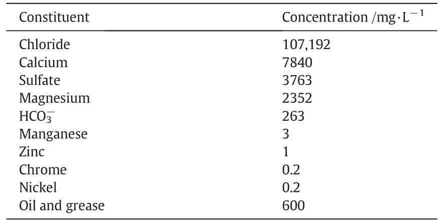
Table 1 Constituents of Al-Ahdab oil field produced water
2.2.EC airlift reactor design
An internal loop airlift electrochemical reactor made from acrylic material was used in this study.It comprised two concentric tubes;internal tube of 20 cm long and 4.7 cm diameter and outer tube of 27 cm long and 8 cm diameter given a reactor working liquid volume of 1.75 L.The air was sparged if needed at the bottom of internal tube section called riser(in some experiments the liquid circulation was resulted from the micro bubbles of the generated hydrogen gas at the cathode if no air inlet to riser).The riser/downcomer cross sectional area Ar/Ad=0.537.Two rectangular aluminum plates were inserted in the riser as two electrodes parallel to the liquid circulation direction(plate dimensions were 20 mm×110 mm with 1 mm thickness giving electrode surface area of 22 cm2and the distance between the two electrodes was 2.5 cm),The distance between the bottom of the plates and the bottom of the riser was 2 cm and between the bottom of the plates and liquid level was 19 cm.The distance from the top of the riser to the liquid level(top clearance)was 1 cm.DigitalDC/power supply was used to create the required current.The anode and cathode electrodes were connected to the negative and positive apertures of DC power supply.The required current value was checked by use of a digital ammeter.The reactor's dimensions are shown in Fig.1.
2.3.Procedure
Fouroperating parameters were studied to obtain the optimalconditions for the produced water treatment in the EC airlift reactor.These parameters include current density(from 6.8 to 45.4 mA·cm-2),initial pH(from 3 to 11),EC time,and air flowrate(from 0 to 1 L·min-1).During the experiments,the circulation liquid velocity was monitored and recorded in each run.All the experiments were performed at room temperature(25°C)and atmospheric pressure in batch operation mode(where the reactor is close to the liquid phase).EC airlift reactor performance was evaluated in terms of oil and turbidity removal efficiencies.
The first part of experiments were carried out to study the effect of current density as 6.8,13.6,27,and 45.5 mA·cm-2which corresponds to an electrical current of 0.15,0.3,0.6,and 1 A,respectively.The other parameters where kept constant(initial pH of 7.2 and no air inlet).For each specified current density value,the samples were taken at prespecified EC time intervals.
In the second part of experiments,the effect of initial pH of the produced water was studied from 3 to 11(initial pH value was varied by adding small droplets of NaOH or HCl solution as required)while the other parameters kept constant.No air was pumped in this part and the current density was fixed at 27 mA·cm-2.pH values were also monitored and recorded during electrocoagulation process.
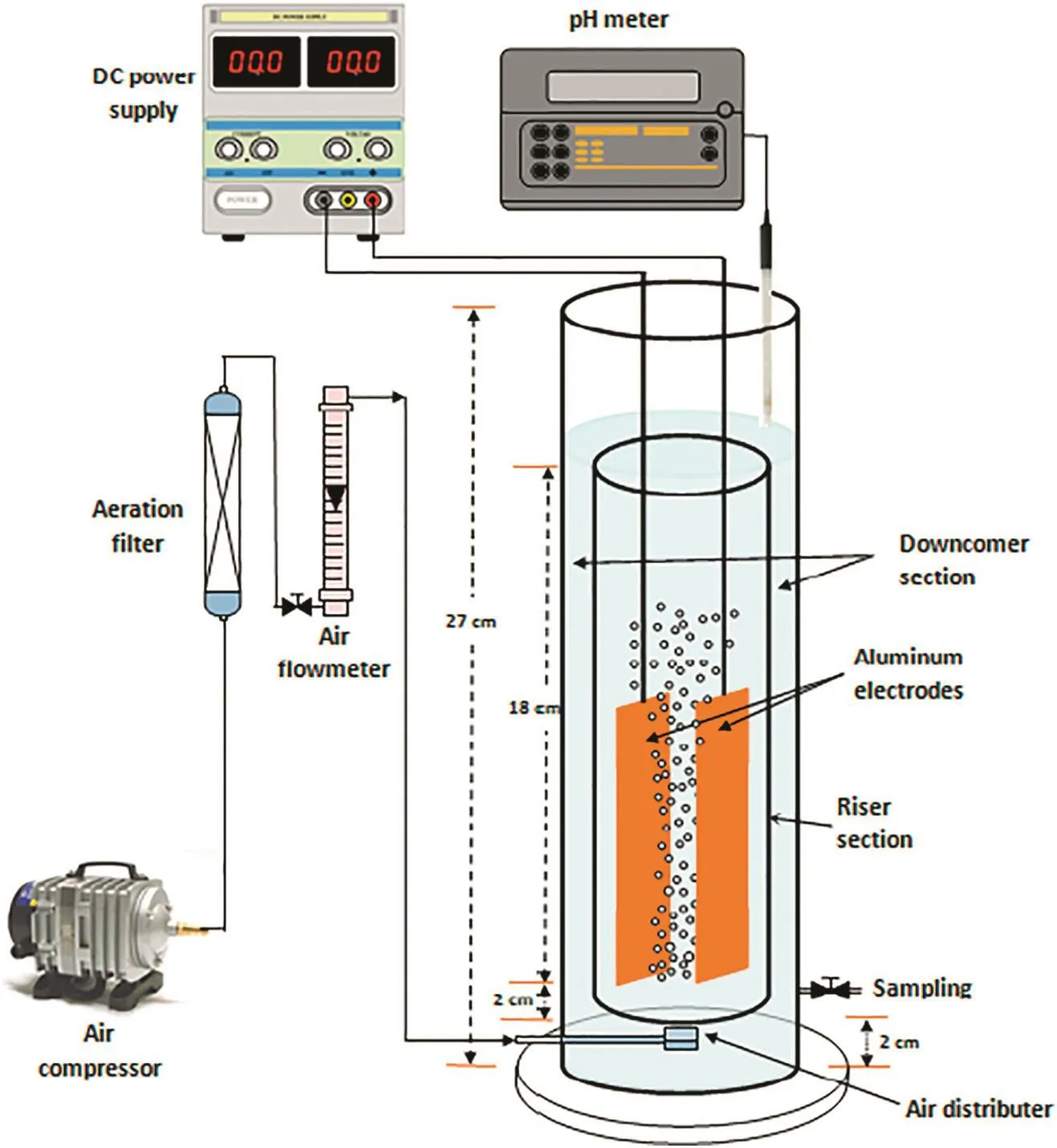
Fig.1.Experimental apparatus of Internal loop EC airlift reactor system used for electrocoagulation treatment of produced water.
In the final part,air was pumped in the riser at different flowrate(from 0.1 to 1 L·min-1),while the other parameters were fixed as 27 mA·cm-2current density,7.2 initial pH,and 35 min EC time.In this part,oil and turbidity removal efficiencies in addition to the liquid circulation velocity were monitored to investigate the effect of air pumping in the riser of EC airlift reactor.
For determination of liquid circulation velocity,the circulation time in the riser and downcomersections were determined with the method called neutral-buoyancy flow follower.Simply the method depends on the use of a tracer particle that has a distinctive color(in order to be visible clearly in liquids).The diameter of tracer particle was 2 mm and specific gravity was 1.05.The time which elapsed in the downcomer or riser is the time taken by this particle to travel a vertical distance which equal to the riser height plus half distance between top of the riser and liquid level plus half distance between bottom of the riserand base ofthe reactor.The circulation time wasmonitored and recorded for downcomer and riser using a digital camera.The procedure was repeated several times and the liquid velocity for each section was calculated from the average of 10 trials[13,14].
2.4.Sample analysis
In every run,about 2 ml of sample was taken for analysis from the sampling slot located 1 cm above the base of the reactor;the samples were allowed to settle for more than 15 min and then filtered.For analysis of oil content,TD-500D Handheld oil in water analyzer(Turner Designs Hydrocarbon Instruments Co.)was utilized.TDS was determined by TDS-meter(161002 PurePro Co.).TSS and Turbidity were determined by TSS Portable Hand-held Turbidity,and suspended solids meter(Hach LXV322.99.00002)and the pH was measured by using pH meter(HANNAInstruments Co.).The oil and turbidity removalefficiencies were determined using following equation:

where,
R is oil or turbidity removal efficiency(%);Y0is initial oil(mg·L-1)or turbidity(NTU),and Ytis oil(mg·L-1)or turbidity(NTU)after time(t).
3.Results and Discussions
3.1.Effect of current density and EC time
Figs.2 and 3 show the effectofcurrentdensity and EC time on the oil and turbidity removals respectively at initial pH of 7.2 and no air pumped.Results show that oil and turbidity removals increase rapidly when current density increases.With increasing current density,the rate of anodic dissolution increases which resulting in more precipitate for the removal of oil.On the other hand,the rate of small hydrogen bubbles generation increases from the cathode and therefore increasing bubble densities and high emulsi fied oil removal by hydrogen flotation[15].
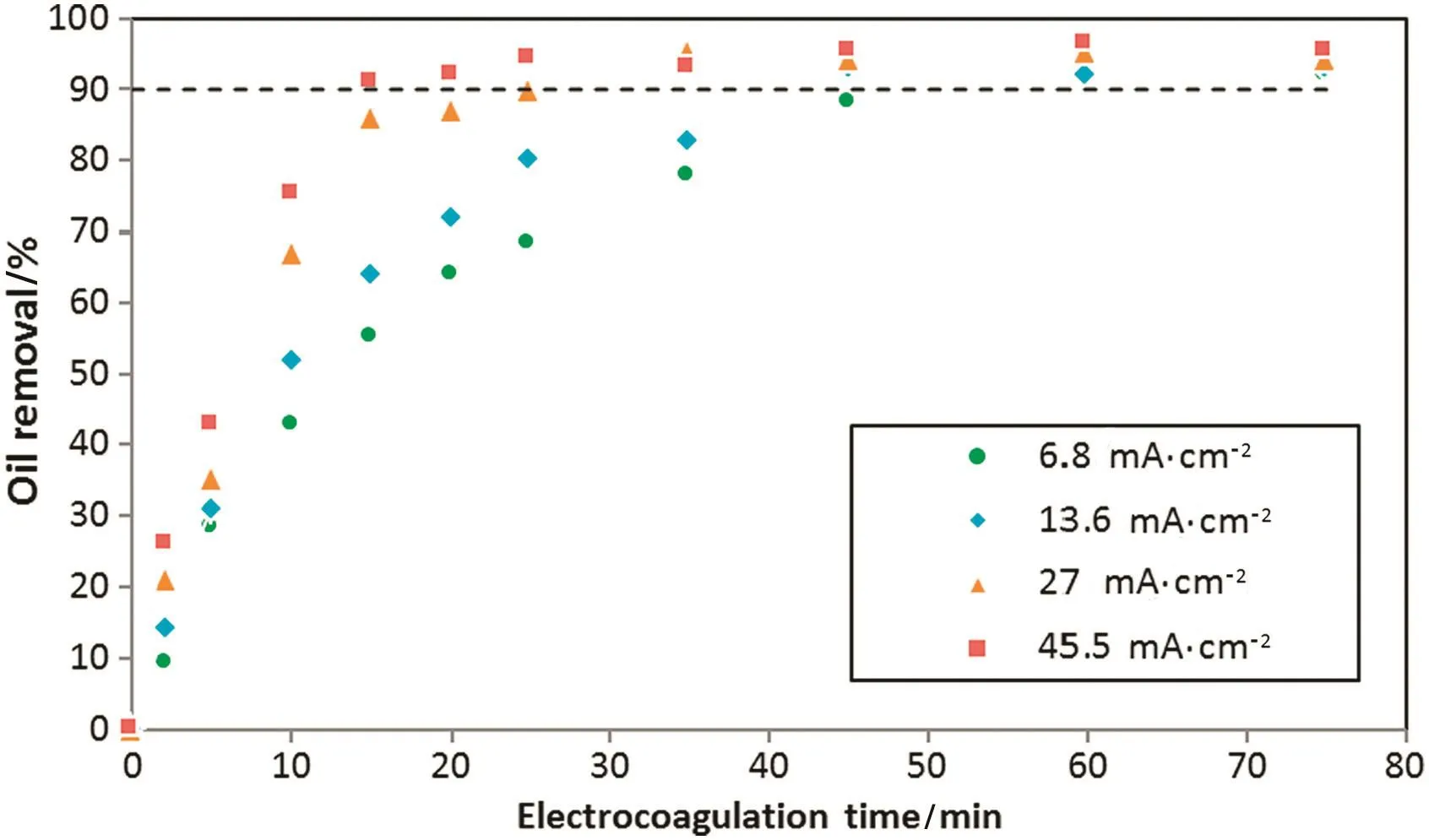
Fig.2.Effect of current density and electrocoagulation time on the oil removal efficiency:initial oil content:600 mg·L-1,initial pH:7.2.
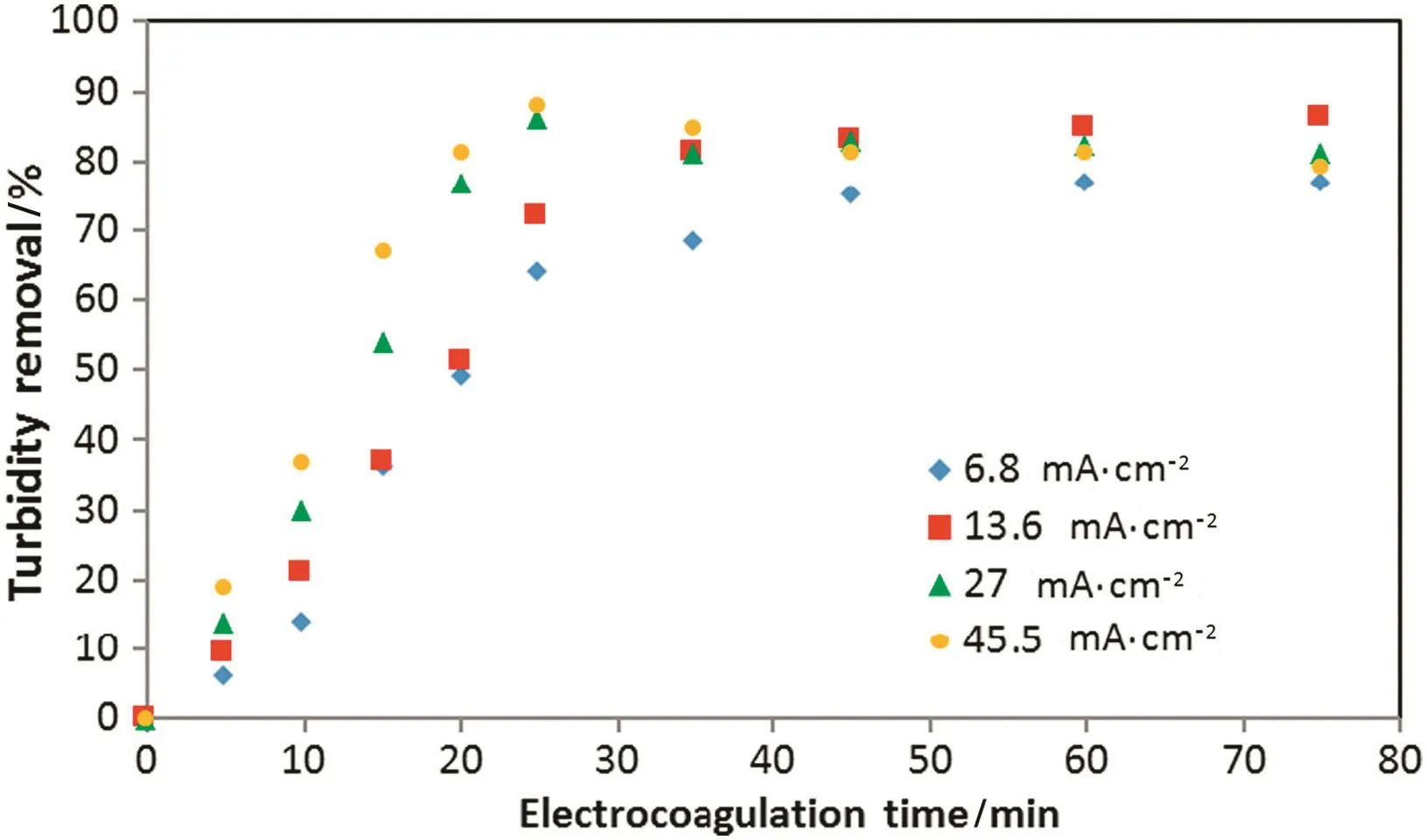
Fig.3.Effect of current density on the turbidity:initial oil content:600 mg·L-1,initial pH:7.2.
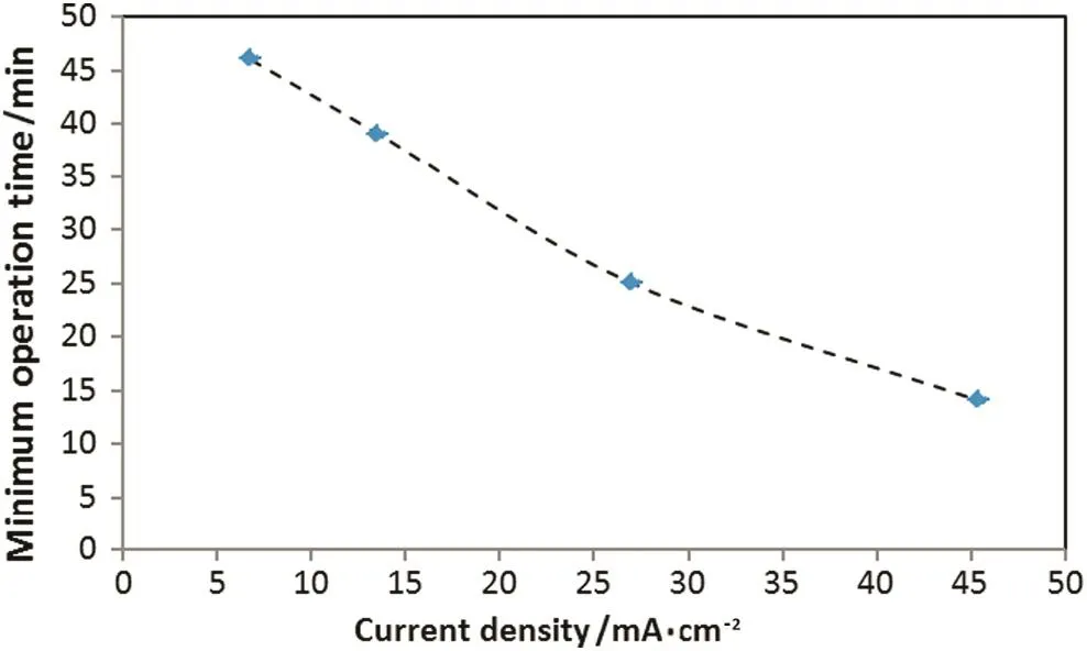
Fig.4.Minimum operation time value for≥90%oil removal at different current density:initial oil content:600 mg·L-1,initial pH:7.2.
The electrocoagulation time required oil removal of≥90%threshold decreases from 46 to 15 min when operating current density increases from 6.8 to 45.5 mA·cm-2.Fig.4 shows the minimum operation time value for≥90%oil removal at different current density.Turbidity removal curve(Fig.3)follows a different behavior,which was expected because the oil constitute is not the only source of pollution in this study.Turbidity removal efficiency increase with increasing of current density,but for high current density value and long electrocoagulation time,turbidity removal percent decreases.This behavior may be attributed to the formation of large amount of Al(OH)3coagulating agent that has difficulties to flocculate and float[8].
The emulsion stability of oil droplets was explained by Helmholtz theory of the electrical double layers[16].The breaking of oil-in-water emulsion through electrocoagulation process is accomplished as follows:
(1)Formation of Al3+by the electrochemical dissolution of the anode:

(2)At the same time,hydrogen micro bubbles are generated from the cathode:
(3)
(4)Al3+and OH-ions react in the bulk produced water to form aluminum hydroxide coagulates:
(5)Formation of(oil droplets–coagulates complex)due to coagulation,neutralization the charge of the oil droplets by counter ions produced which reduce the electrostatic repulsion between droplets and make them less stable.
(6)Hydrogen micro bubbles adhere to oil droplets-coagulates complex make them rise to the top of the reactor.
Increasing current density leads to increase liquid circulation velocity due to the increase the hydrogen micro bubbles generated at the cathode.It was noted that the liquid circulation between the riser and downcomer sections was achieved even by small bubbles of hydrogen gas at the cathode electrode when no air bubbled in the riser.
Fig.5 shows the liquid circulation velocity versus current density.Increasing hydrogen generation with large amount and small size bubbles in the riser section leads to increase gas holdup and therefore liquid circulation due to density difference between the two sections of the reactor.This behavior of the gas holdup effect on the liquid circulation velocity is wellknown by many hydrodynamic studies of two phase airlift contactors as specified by[5].The double positive effect of current density on the oil removal efficiency(and therefore turbidity)is due to two reasons: firstly,the formation more coagulating agent(such as Al(OH)3)due to increasing the rate ofanode oxidation reaction and secondly,good mixing in the reactor which resulted from increasing circulation velocity by more micro bubbles of hydrogen at the cathode.This means more coagulating agent is being contacted with colloidal oil which leads in the two cases to improve the oil removal.This mechanism is illustrated in Fig.6.
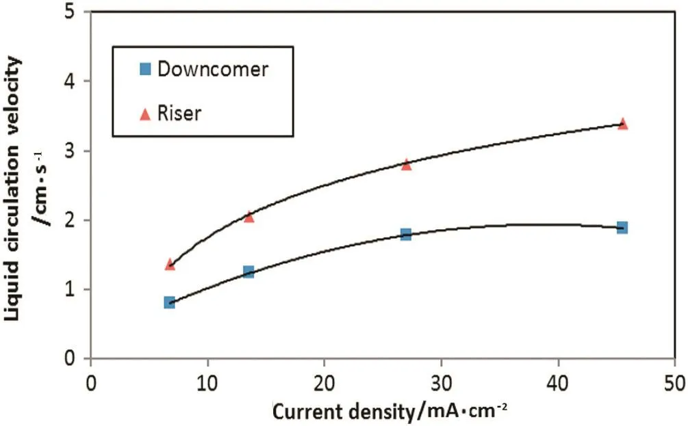
Fig.5.Effect of current density on the overallliquid circulation velocity in the downcomer and riser:initial oil content:600 mg·L-1,initial pH:7.2.
3.2.Effect of initial pH
The effect of the initial pH on oil and turbidity removals is shown in Fig.7 at constant current density(27 mA·cm-2)and operation time of 35 min.As shown in this figure,the optimum removal condition is for the initial pH,which was between 7 and 9.As initial pH increased beyond 9,the decline of the oil and turbidity removal efficiencies were observed due to less formation of the reactive flocs of aluminum hydroxide.Also Fig.8 shows the pH changed during electrocoagulation process,while Fig.9 shows the relation between initial and final pH;it's clear that the pH profile depended on the initial pH,but it does not change significantly due to the balance between the formation and the consumption of OH-ions[17].As shown in Fig.9,the treatment induced an increase in the final pH when the initial pH was low.This might be attributed to the excess of OH-ions generated in acidic conditions and by the liberation of OH-due to the occurrence of a partial exchange of Cl-with OH-in Al(OH)3coagulants[18].When the initial pH is above 8,the formation of Al(OH)4-species together with parasite attack of the cathode by OH-ions lead to a slightdecrease in the final pH.
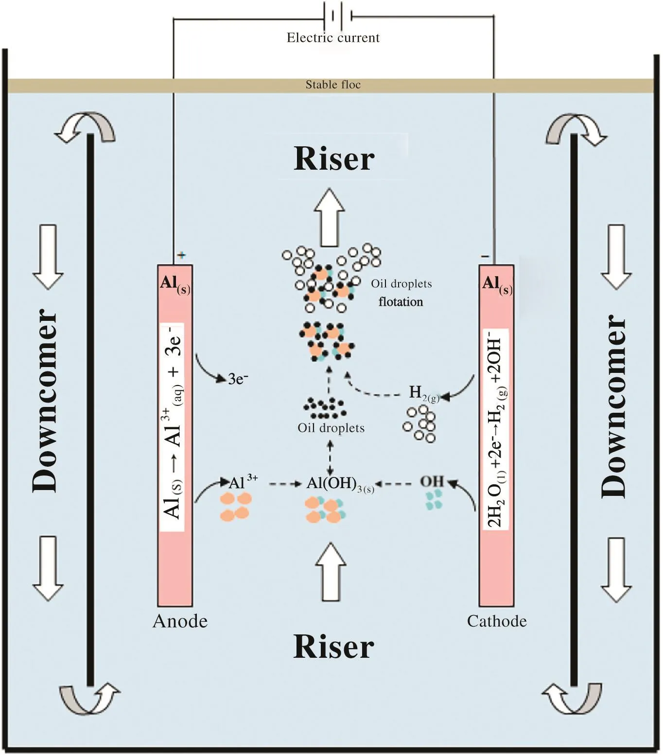
Fig.6.Schematic view of the airlifting-electrocoagulation/ flotation hybrid system.
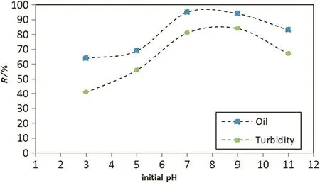
Fig.7.Oil and turbidity removal efficiency versus initial pH at 35-min operation time and current density of 27 mA·cm-2.
3.3.Energy consumption
In this work,the specific electrical energy consumption per kg oil removed(Eoil,kW·h·kg-1)was calculated from the following equation[8]:

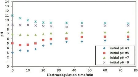
Fig.8.pH profile during electrocoagulation process of produced water at different initial pH and at current density of 27 mA·cm-2.
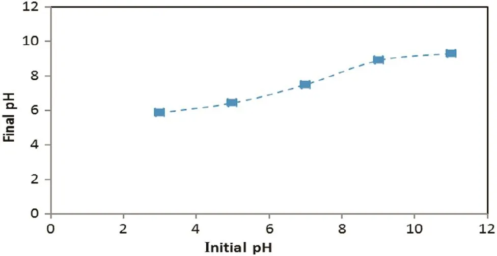
Fig.9.pH variation after electrocoagulation(current density:27 mA·cm-2,time of electrocoagulation:75 min)
For initial oil content C0(600 mg·L-1),current I(A),voltage U(V),electrocoagulation time t(h)and produced water volume V(L).The electrocoagulation time was determined at 90%removal efficiency(R).Fig.10 shows the in fluence of current density on electrical energy requirements per kg oil removed(Eoil)at operation time for which oil removal is at 90%,while Fig.11 shows the electrical energy consumption during operation time.Energy consumption during EC process is known to vary according to the product UIt.As expected,Fig.10 shows a continuous increase of energy consumption with current density,which has already been noted in the literature for many polluted wastewater[19,20].The minimum time required to achieve 90%oil removal affect the energy requirements,butdecrease in this time does notcompensate the effect of current density increase on energy requirements.In conventional EC equipment,electrical energy cost represents only from 20%–50%of the total operating costs of EC,while the other costs includes electrode material and mechanical agitation[21].However,there is no mechanical stirrer in proposed EC reactor and the electrode material cost was not considered in this study.From the point of view of specific energy consumption and to avoid releasing excess Al(OH)3in bulk,the best conditions correspond to a low current and a high EC time,such as 6.8 mA·cm-2(I=0.15A)and t=46 min.In fact,Eoilis proportional to t,but varies roughly as I2because of Ohm's law.

Fig.10.In fluence of current density on specific electrical energy consumption(E oil)at operation time for which oil removal of 90%(initial oil content:600 mg·L-1,initial pH:7.2).
3.4.Effect of air pumping
Fig.12 depicts the effect of different air flowrate on the oil removal efficiency at current density of 27 mA·cm-2and initial pH of 7.2.When air sparged to the riser(internal tube),the circulation velocity increases gradually.This Figure indicates that internal-loop airlift reactor when used as electrocoagulation/ flotation cell was very successful even without using air.Using air in this EC reactor may increase the removal efficiency by two ways, firstly,the mixing of the reactor contentincrease and therefore electrical conductivity increased.Moreover pumping air in the EC reactor increase the flotation rate of oil droplets–coagulates complex.
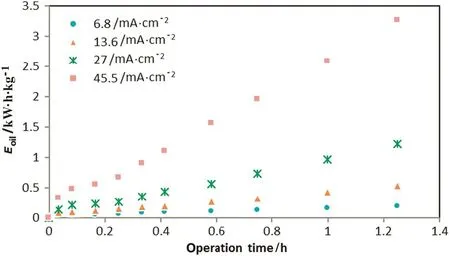
Fig.11.In fluence of current density and operation time on electrical energy consumption,E oil(initial oil content:600 mg·L-1,initial pH:7.2).
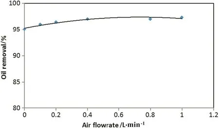
Fig.12.Effect of air flowrate on oil removal efficiency(EC time:35 min,initial oil content:600 mg·L-1,initial pH:7.2 and current density of 27 mA·cm-2).
In this EC reactor,airpumping can be dispensable and therefore eliminating the additional cost and suf ficiency of hydrogen microbubbles from cathode only to circulate the liquid between the riser and downcomer.Oil removal efficiency does not increase significantly when increasing air flowrate,as shown from Fig.12;at certain conditions the oil removal efficiency increased from 95%to 97.3%only when increasing air flow from 0 L·min-1to 1 L·min-1respectively.Also,using high air flow rate can cause a very high mixing of the reactor contents and breaking the floc layer of contaminants floating on the surface of the reactor.
4.Conclusions
In this study,produce water was treated in internal-loop airlift reactor with high efficiency.Internal-loop airlift reactor has been shown to be a multiuse equipment that can carry out electrocoagulation process with efficient flotation,using only H2bubbles generated from the cathode electrode.Therefore,an overall liquid circulation between riser and downcomer and good mixing conditions were obtained.Batch experiments on produce water treatment,with 90%oil and turbidity removal as the targets,showed that the electrical energy consumption in this equipment was low in the current density range studied.The double positive effect of increasing the current density in this reactor on the oil removal efficiency comes from two reasons:The first reason is due to increased oxidation and reduction reactions rate.The second reason is the good mixing resulting from the circulation of liquid between the two parts due to hydrogen bubbles generated from the cathode electrode without the need of compressed air or mechanical energy requirements for mixing.
References
[1]P.R.Jams,F.R.Engelhardt,Produced Water:Technological/Environmental Issues and Solutions,Springer,California,1992.
[2]J.Gomes,D.Cocke,K.Das,M.Guttula,D.Tran,J.Beckman,Treatment of produced water by electrocoagulation,EPD Congress 2009:Proceedings of Sessions and Symposia Held during TMS 2009 Annual Meeting&Exhibition,San Francisco,California 2009,pp.15–19.
[3]M.Y.A.Mollah,R.Schennach,J.R.Parga,D.L.Cocke,Electrocoagulation(EC)—science and applications,J.Hazard.Mater.84(1)(2001)29–41.
[4]M.M.Emamjomeh,M.Sivakumar,Reviewofpollutants removed by electrocoagulation and electrocoagulation/ flotation processes,J.Environ.Manag.90(5)(2009)1663–1679.
[5]M.Y.Chisti,Airlift Bioreactors(Vol.39),Elsevier,New York,1989.
[6]R.Di Felice,Liquid circulation rates in two-and three-phase external airlift reactors,Chem.Eng.J.109(1)(2005)49–55.
[7]W.Balla,A.H.Essadki,B.Gourich,A.Dassaa,H.Chenik,M.Azzi,Electrocoagulation/electro flotation of reactive,disperse and mixture dyes in an external-loop airlift reactor,J.Hazard.Mater.184(1)(2010)710–716.
[8]A.H.Essadki,M.Bennajah,B.Gourich,C.Vial,M.Azzi,H.Delmas,Electrocoagulation/electro flotation in an external-loop airlift reactor—application to the decolorization oftextile dye wastewater:a case study,Chem.Eng.Process.47(8)(2008)1211–1223.
[9]A.H.Essadki,B.Gourich,C.Vial,H.Delmas,M.Bennajah,De fluoridation of drinking water by electrocoagulation/electro flotation in a stirred tank reactor with a comparative performance to an external-loop airlift reactor,J.Hazard.Mater.168(2)(2009)1325–1333.
[10]H.K.Hansen,P.Nunez,D.Raboy,I.Schippacasse,R.Grandon,Electrocoagulation in wastewater containing arsenic:comparing different process designs,Electrochim.Acta 52(10)(2007)3464–3470.
[11]H.Chenik,M.Elhafdi,A.Dassaa,A.H.Essadki,M.Azzi,Removalof real textile dyes by electrocoagulation/electro flotation in a pilot external-loop airlift reactor,J.Water Resour.Prot.5(10)(2013)1000.
[12]J.Behin,N.Farhadian,M.Ahmadi,M.Parvizi,Ozone assisted electrocoagulation in a rectangular internal-loop airlift reactor:application to decolorization of acid dye,J.Water Proc.Eng.(8)(2015)171–178.
[13]W.J.Lu,S.J.Hwang,C.M.Chang,Liquid mixing in internal loop airlift reactors,Ind.Eng.Chem.Res.33(9)(1994)2180–2186.
[14]S.H.Ammar,S.S.Abdu-Majeed,Performance evaluation of an internal-loop airlift reactor for phenolic wastewater treatment by adsorption onto activated carbon,Int.J.Curr.Eng.Technol.6(1)(2016).
[15]G.J.Rincon,E.J.La Motta,Simultaneous removal of oil and grease,and heavy metals from artificial bilge water using electro-coagulation/ flotation,J.Environ.Manag.144(2014)42–50.
[16]A.G.Volkov,D.W.Deamer,D.L.Tanelian,V.S.Markin,Electrical double layers at the oil/water interface,Prog.Surf.Sci.53(1)(1996)1–134.
[17]G.Chen,Electrochemical technologies in wastewater treatment,Sep.Purif.Technol.38(1)(2004)11–41.
[18]A.Fakhru'l-Razi,A.Pendashteh,L.C.Abdullah,D.R.A.Biak,S.S.Madaeni,Z.Z.Abidin,Review of technologies for oil and gas produced water treatment,J.Hazard.Mater.170(2)(2009)530–551.
[19]M.Kobya,E.Demirbas,O.T.Can,M.Bayramoglu,Treatment of leva fix orange textile dye solution by electrocoagulation,J.Hazard.Mater.132(2006)183–188.
[20]M.Y.A.Mollah,P.Morkovsky,J.A.G.Gomes,M.Kesmez,J.R.Parga,D.L.Cocke,Fundamentals,present and future perspectives of electrocoagulation,J.Hazard.Mater.114(2004)199–210.
[21]M.Bayramoglu,M.Kobya,O.T.Can,M.Sozbir,Operating cost analysis of electrocoagulation of textile dye wastewater,Sep.Purif.Technol.37(2004)117–125.
 Chinese Journal of Chemical Engineering2018年4期
- Chinese Journal of Chemical Engineering的其它文章
- An innovative design of septic tank for wastewater treatment and its performance evaluation:An applicable model for developing countries
- From pollutant to solution of wastewater pollution:Synthesis of activated carbon from textile sludge for dye adsorption
- 17α-Ethinylestradiol removal from water by magnetic ion exchange resin☆
- Transesteri fication of sun flower oil in microchannels with circular obstructions
- The extraction of potassium from K-feldspar ore by low temperature molten salt method☆
- Decomposition behavior of CaSO4 during potassium extraction from a potash feldspar-CaSO4 binary system by calcination☆
