Crack deflection occurs by constrained microcracking in nacre
Jingru Song·Cuncai Fan·Hansong Ma·Lihong Liang·Yueguang Wei
1 Introduction
Almost all engineering structural materials are required to be both strong and tough(damage-tolerant),but these two mechanical properties are mutually exclusive[1].For some mineralized biological tissues,this conflict has been resolved by incorporating hard minerals into soft organic matrices,producing sophisticated composites with certain combinations of stiffness,toughness,and strength to meet the physiological demand for structural support and armored protection[2–4].Mollusk shell is an extraordinary example that exhibits excellent mechanical properties. In past decades,it has been of great interest to material scientists and engineers,as it promises to be a model for synthetic ceramic composite[5–8].

In the present study,we use the three-point bending test of dehydrated nacre in situ with a scanning electron microscope(SEM)to discern how cracksevolve and form the consequent deflection outline.Finally,a crack propagation model is proposed based on our experiments,which will help us obtain a comprehensive understanding of the underlying mechanisms for nacre’s superior fracture toughness.

Fig.1 Schematic of bending tested specimens(units in millimeter).Red circle denotes the position of SEM imaging
2 Experimental methods
The hard shells ofHyriopsis cumingii,a kind of limnetic oyster,were obtained from south of China and cut into strips using a low-speed diamond saw,with the outer periostracum and prismatic layers ground off.Then,they were rinsed thoroughly in constant irrigation of water.The specimens for SEM observation were mechanically polished and subsequently etched with 10 wt% ethylenediaminetetraacetic acid disodium salt(EDTA-2Na)solutions for 10 min.The specimens for bending tests were cut into small beams,carefully polished,and then stored at room temperature for 3 months to ensure complete dehydration.All specimens were coated with a thin film of gold prior to SEM imaging.
The shapes and sizes of the specimens used in the bending test are shown in Fig.1.The first specimen(see Fig.1a)was tested as in previously reported investigations:controlled bending deflection was gradually applied to the specimen(at the rate of 0.55μm/s)until it eventually ruptured,followed by the analysis of its macro-appearance,loading–displacement curve measurement,and failure microstructure.By comparison,the second notched specimen was mounted to a micromechanical tester which was integrated with an SEM to image the nacre surface(the area of the red circle in Fig.1b)during the experiment.Once the crack was initiated on the surface at the notch root,the loading was temporarily suspended for SEM imaging.As the crack tip terminated in the nacre,additional controlled deflection was applied again and immediately suspended if the crack resumed extending.This method allowed control over the crack growth rate and the real-time monitoring of morphology evolutions during testing.The fracture mechanism for the nacre material will be developed and the fracture process will be modeled.
3 Experimental observation and measurement
3.1 Hierarchical structure
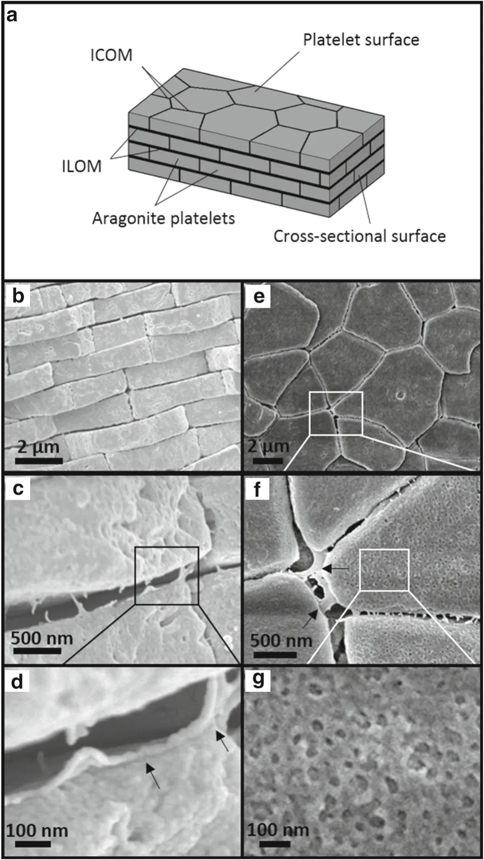
Nacre has a complex hierarchical architecture that spans multiple length scales from nanometers to millimeters.Figure 2a presents a schematic of nacre.On the platelet surface,it is polygon-shaped(see Fig.2e),while on the cross-sectional surface,it exhibitsa so-called brick-and-mortar structure(see Fig.2b).In general,there are two kinds of nacre:columnar nacre and sheet nacre[12].The distinction between them lies in the stacking mode of aragonite platelets and the ultrastructural features on their surfaces.Here,our sample from the shell ofHyriopsis cumingiiis of the sheet type,whose aragonite platelets are randomly stacked,with no nano-apsperites on the surface and no mineral bridges between them,as shown in Fig.2b,c.Based on these observations,the aragonite platelets were measured as 4.60±1.67μm in length,and 0.93±0.17μm in thickness.
In addition,the magnified images revealed the existence of organic biopolymer(about 30 nm in thickness)between platelets.This inter-platelet organic matrix(IPOM)can be subdivided into two types:inter-laminar organic matrix(ILOM,black arrow in Fig.2d)and inter-crystalline organic matrix(ICOM,black arrow in Fig.2f).According to the “organic matrix-mediated”theory of surface-templated growth,ILOM precedes ICOM during the biomineralization process;thus they may be different in both structure and composition[26–29].Also,it is worth noting that intracrystalline organic biopolymer embedded inside individual mineral platelets has recently been detected using different techniques[30–34].In our experiment,the closer examination in Fig.2g on the etched platelet surface clearly exposes the nanograins inside aragonite platelets,consistent with the literature description that the aragonite in nacre is constructed with highly oriented nanoparticles and biopolymers[35,36].It is believed that these organic inclusions have a substantial effect on the mineral platelet’s mechanical properties[37,38].

Fig.2 Hierarchical structure of nacre.a A schematic showing how polygonal aragonite platelets are arranged to form a lamellar structure in nacre.Magnified figures of nacre on cross-sectional surface(b–d)and platelet surface(e–g).ICOM inter-crystalline organic matrix,ILOM inter-laminar organic matrix

Fig.3 Load–deflection curves of the specimen without a notch and the specimen with a single notch
3.2 Three-point bending test
The resulting load–deflection curves are shown in Fig.3.In the first experiment of the sample without a notch(see Fig.1a),the dry nacre behaved like a ceramic material and failed in a brittle fashion(see Fig.3).
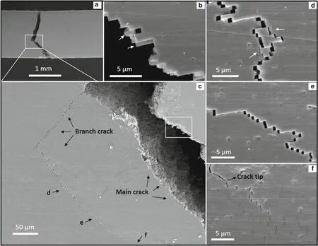
Figure 4 shows its surface morphology after failure.The overall failure form seems to be a combination of two main failure mechanisms from the compressive and tensile zones of the two sides.The magnified image in Fig.4b seems to indicate that the main crack traveled both around and through mineral platelets with broken and intact platelets(white arrow).However,a branch crack(see Fig.4c),which developed and was accompanied by the main crack that came from the tensile zone and terminated in the compressive zone,behavesquite differently.Closer examination along the branch crack exposed the unexpected evolution of a crack which may be the second joint of two failure mechanisms from the compressive and tensile regions,respectively.In the position farbehind the crack tip(see Fig.4d),the fracture path behaves like that of the main crack,but when the observed view moves toward the crack tip(see Fig.4e),no broken platelets are found,indicating that the crack propagated strictly along the biopolymers between aragonite platelets.This assumption is confirmed by the SEM micrograph in the area just ahead of the crack tip(see Fig.4f),which clearly shows the successive stair-like stepson the surface,extending up and down along the biopolymer interlayer.
To fully investigate how crack deflection occurs in nacre,another three-point bending test with a single-notched sample was performed in situ in the SEM.This technique allows us to monitor the evolution of damage mechanisms ahead of the crack tip.In this experiment,a stable fracture from three cycles of loading and unloading(see Fig.3)was observed.

Fig.4 Crack path profile and damage morphology in nacre under a three-point bending test.a The fracture path observation of broken sample.b A closer examination of the white boxed area in c showing the main crack path profile with both broken and intact aragonite platelets(white arrow).c A close-up view of the white boxed area in a showing a branch crack that develops from the main crack.d–f Magnified figures of the branch crack toward the crack tip in positions marked “d”,“e”,and “f”in c
When the load reached around 40 N,a crack initiated at the notch,shown in the white boxed area in Fig.5a.After unloading,the crack propagated slowly with a reduction in load from the point ofAtoBin Fig.3,and finally ended in nacre.During the second loading from the point ofBtoCin Fig.3,the crack resumed propagating.Once unloaded,the crack propagated further with another,smaller reduction in load from the point ofCtoD.Interestingly,the area just ahead of the crack tip began to take the shape of arborization(see Fig.5b).A closer examination of this area in Fig.5c clearly demonstrates the formation of multiple microcracks contained within the ICOM.At the beginning of the third loading from the point ofDtoEin Fig.3,the crack traveled through these constrained microcracks,as shown in Fig.5d.At the same time,some pre-existing microcracks(indicated by the dotted ovals in Fig.5c,d)were preserved beside the main crack,while some new microcracks were produced continually(indicated by the dotted squares).In conclusion,these observations clearly reveal that crack deflection in nacre occurs by constrained microcracking,and this mechanism allowed for stable growth of the crack until the final failure at the point ofFin Fig.3.
3.3 Crack propagation process
To better understand the development and morphology of microcracking in nacre,a schematic model is proposed in Fig.6.The application of deflection results in the initiation of a crack at the notch root and the subsequent formation of a microcrack zone ahead of the crack tip.These microcracks are confined between aragonite platelets in ICOM(stage I).With continued loading,the main crack propagates through this zone.Meanwhile,some new microcracks are being produced ahead of the main crack tip(indicated by the dotted square),while some pre-existing microcracks(indicated by dotted ovals)are preserved beside the main crack(stage II).Stage II continues until a local saturation of microcracks in the area ahead of the crack tip is achieved.The main crack propagates again to repeat stage I,followed by stage II.This pattern of alternating stages I and II is repeated as the main crack continues to propagate stably through the nacre.
Over recent decades,it has been understood that nacre’s principal toughening strategy is at the crack deflection along the biopolymer interface.Our findings,however,clearly show that the crack deflection in nacre does not happen directly,but rather occurs by constrained microcracking ahead of the main crack tip.The presence of such microcracks initiated ahead of the main growing crack can effectively release the local stress concentration that would otherwise cause the nacre to fracture,thus enhancing the crack extension resistance.Most importantly,as with other biological mineralized composites such as bone,microcracking is advantageous for the development of crack deflection,as fracture is closely associated with the intrinsic(damage)mechanisms ahead of the crack tip that promote cracking[39–41].The crack deflection in return provides the greatest contribution to nacre’s toughness.Nevertheless,our experiments were conducted under a quasi-static state.Some recent studies have shown that nacre exhibits much higher fracture strength under high-strain-rate loading,which is attributed to the fracture transition from crack deflection to invasion through the aragonite platelets[42,43].Here,we can reasonably speculate that the fracture transition might be caused by the suppression of nucleation of microcracks under a high strain-rate state.

Fig.5 In situ SEM micrographs reveal the evolution of damage mechanisms ahead of the crack tip.a A crack initiates at the notch.b The crack terminates in nacre with a shape of arborization atcrack tip(white boxed).c,d Sequential snapshots show that crack deflection occurs by constrained microcracking,with some microcracks preserved(in dotted ovals)and some newly produced(in dotted squares).The black arrows in c and the dotted line with arrow in d show the main crack path profile under continued loading;the light areas in d indicate electrical charging in the SEM resulting from the deformation of the gold coating during crack propagation
In addition,our investigations are significant in uncovering the evolution of damage morphology in nacre.Consistent with the common belief that the organic biopolymer layers are so well bonded to the mineral platelets,microcracking is able to be activated,followed by crack deflection.Therefore,the aragonite platelets invariably remain shielded from the propagating crack,resulting in a “ragged platelet”morphol-ogy.However,with increasing displacement,some separated platelets are broken off due to the interaction between adjacent ones.This is very important,considering a recently proposed assumption that crack invasion might occur at the crack tip,as the intra-crystalline organic matrix inside individual platelets serves as defects,leading to cracking[38].Our research,on the other hand,indicates that such organic inclusions actually strengthen the mineral platelet by modifying it into a nanoparticle architecture which becomes insensitive to flaws[6].This is verified by the direct evidence that the microcracks arise from ICOM instead of from the inside the aragonite platelets;however,more quantitative details are needed to further evaluate nacre’s mechanical design.

Fig.6 Schematic model showing the development of crack deflection through microcracking in nacre

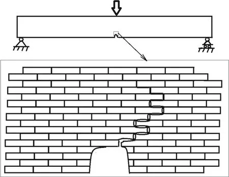
Fig.7 Crack propagation model for nacre under three-point bending due to interfacial shear sliding
4 Modeling of the energy release rate
Referring to the experimental observation in Fig.5,we present a small-scale damage zone model as shown in Fig.7,near the notch,a crack forms and propagates due to bending and interfacial shear sliding between bricks.
When the damage zone is small,the energy release rate is written as follows

whereΠis the total potential of the system,ais crack length,andBis the width of the beam.

whereUis the strain energy of the beam,Pis the load,and
Δis the deflection of the central point of the beam(point acted on by load).For the case of small beam deformation and small-scale damage,Uis bending energy

for a three-point bend beam,whereLis beam length,Eis Young’s modulus,andIis inertial momentum

for the rectangular section of the beam,wherehis the height of beam.Equation(2)can be rewritten as follows

whereΔ0is the deflection at the central point of the beam when the beam is without a notch,

The load–deflection curves for un-notched and notched beams are shown in Fig.3a,b,respectively.
The crack propagation condition can be expressed as follows

whereΓ0is the elastic fracture toughness(or elastic fracture energy density),andΓDis the damage dissipation energy density due to sliding between bricks.Based on the model sketched in Fig.7,we further assume that shear stress within the organic layer can be described as

where|Δu|is the relative sliding displacement between two bricks,(τs,γs)is the shear strength and shear strain of the organic layer,andlis the sliding zone length between two neighboring bricks.ThusΓcan be expressed as

whereρ=1/tis the density of a “brick”in the vertical direction,tis brick thickness,anddis the width of the damage zone.
5 A simple comparison of model results with experimental results for the energy release rate
From experimental observation,as seen in Fig.4,the form of failure for both a notched and un-notched specimen is cross-section fracture.From the load–displacement curve,as shown in Fig.3,one can obtain the average energy release rates by calculating the area under the load–displacement curves divided by the cross-section area of the specimen:ˉG=Γ0≈200 J·m?2for a specimen without a notch,andˉG≈303 J·m?2for a specimen with a notch.On the other hand,one can also use the theoretical model given in Sect.4(see Eqs.(7)–(9))to calculate the energy release rate.From Fig.2b,c,t~ 0.93μm,l~ 4.6μm,and from Fig.5c or d,d~ 18μm,in addition toτs≈ 37 MPa,andγs=τs/μs≈0.038 from Refs.[44,45],one can obtain the energy release rateˉG=Γ0+ΓD≈325 J·m?2,whereΓ0≈200 J·m?2is the energy release rate of a specimen without a notch.
6 Conclusions
The nacreous layer from the shell ofHyriopsis cumingiihas a sophisticated structure with a rigid hierarchical design that can generate high fracture toughness,primarily by crack deflection.Under a quasi-static loading state,crack deflection occurs by constrained microcracking.This crack propagation model contributes to our understanding of the toughening mechanisms of nacre in at least two ways:First,the microcracking just ahead of the crack tip can effectively release the local stress concentration,thus enhancing the crack extension resistance.Second,the formation of microcracking is advantageous for the main crack to propagate along biopolymer layers and to dissipate the most energy,namely becoming tougher.Furthermore,this model also contributes to uncovering the evolution of damage morphology and the distinctive mechanical responses between high strain rate and a quasi-static state.In summary,it is expected that the present experimental findings shall be quite helpful to inspire us in replicating nacre’s mechanical design.
AcknowledgementsThis work was supported by the National Natural Science Foundation of China(Grants 91216108,11432014,11672301,11372318,and 11502273)and the Strategic Priority Research Program of the Chinese Academy of Sciences(Grant XDB22040501).
1.Ritchie,R.O.:The conflicts between strength and toughness.Nat.Mater.10,817–822(2011)
2.Wegst,U.G.K.,Ashby,M.F.:The mechanical efficiency of natural materials.Philos.Mag.84,2167–2186(2004)
3.Launey,M.E.,Ritchie,R.O.:On the fracture toughness of advanced materials.Adv.Mater.21,2103–2110(2009)
4.Song,J.R.,Fan,C.C.,Ma,H.S.,et al.:Hierarchical structure observation and nanoindentation size effect characterization for a limnetic shell.Acta.Mech.Sin.31,364–372(2015)
5.Kamat,S.,Su,X.,Ballarini,R.,et al.:Structural basis for the fracture toughness of the shell of the conch Strombus gigas.Nature 405,1036–1040(2000)
6.Gao,H.,Ji,B.,J?ger,I.L.,et al.:Materials become insensitive to flaws at nanoscale:lessons from nature.Proc.Nat.Acad.Sci.100,5597–5600(2003)
7.Mayer,G.:Rigid biological systems as models for synthetic composites.Science 310,1144–1147(2005)
8.Mayer,G.:New toughening concepts for ceramic composites from rigid natural materials.J.Mech.Behav.Biomed.Mater.4,670–681(2011)
9.Currey,J.D.,Taylor,J.D.:The mechanical behaviour of some molluscan hard tissues.J.Zool.173,395–406(1974)
10.Jackson,A.P.,Vincent,J.F.V.,Turne,R.M.:Comparison of nacre with other ceramic composites.J.Mater.Sci.25,3173–317(1990)
11.Jackson,A.P.,Vincent,J.F.V.,Turner,R.M.:The mechanical design of nacre.Proc.R.Soc.Lond.B Biol.Sci.234,415–440(1988)
12.Wang,R.Z.,Suo,Z.,Evans,A.G.,et al.:Deformation mechanisms in nacre.J.Mater.Res.16,2485–2493(2001)
13.Evans,A.G.,Suo,Z.,Wang,R.Z.,et al.:Model for the robust mechanical behavior of nacre.J.Mater.Res.16,2476(2001)
14.Zuo,S.C.,Wei,Y.G.:Microstructure observation and mechanical behavior modeling for limnetic nacre.Acta.Mech.Sin.24,83–89(2008)
15.Barthelat,F.,Tang,H.,Zavattieri,P.D.,et al.:On the mechanics of mother-of-pearl:a key feature in the material hierarchical structure.J.Mech.Phys.Solids 55,306–337(2007)
16.Wang,R.,Gupta,H.S.:Deformation and fracture mechanisms of bone and nacre.Annu.Rev.Mater.Res.41,41–73(2011)
17.Wang,R.Z.,Wen,H.B.,Cui,F.Z.,et al.:Observations of damage morphologies in nacre during deformation and fracture.J.Mater.Sci.30,2299–2304(1995)
18.Jackson,A.P.,Vincent,J.F.V.,Turner,R.M.:The mechanical design of nacre.Proc.R.Soc.Lond.B 234,415–440(1988)
19.Sarikaya,M.,Gunnison,K.E.,Yasrebi,M.,et al.:Mechanical property-microstructural relation ships in abalone shell.Mater.Res.Soc.174,109–116(1990)
20.Yao,H.M.,Song,Z.G.,Xu,Z.P.,et al.:Cracks fail to intensify stress in nacreous composites.Compos.Sci.Technol.81,24–29(2013)
21.Xie,Z.Q.,Yao,H.M.:Crack deflection and flaw tolerancein“brickand-mortar”structured composites.Int.J.Appl.Mech.6,1450017(2014)
22.Feng,Q.L.,Cui,F.Z.,Pu,G.,etal.:Crystal orientation,toughening mechanisms and a mimic of nacre.Mater.Sci.Eng.C 11,19–25(2000)
23.Song,F.,Zhang,X.H.,Bai,Y.L.:Microstructure and characteristics in the organic matrix layers of nacre.J.Mater.Res.17,1567–1570(2002)
24.Meyers,M.A.,Chen,P.Y.,Lin,A.Y.M.,et al.:Biological materials:structure and mechanical properties.Prog.Mater Sci.53,1–206(2008)
25.Katti,K.S.,Katti,D.R.,Pradhan,S.M.,et al.:Platelet interlocks are the key to toughness and strength in nacre.J.Mater.Res.20,1097–1100(2005)
26.Bevelander,G.,Nakahara,H.:An electron microscope study of the formation of the nacreous layer in the shell of certain bivalve molluscs.Calcif.Tissue Res.3,84–92(1969)
27.Weiner,S.,Traub,W.,Parker,S.B.:Macromolecules in mollusc shells and their functions in biomineralization.Philos.Trans.R.Soc.Lond.B Biol.Sci.304,425–434(1984)
28.Sch?ffer,T.E.,Ionescu-Zanetti,C.,Proksch,R.,et al.:Doesabalone nacre form by heteroepitaxial nucleation or by growth through mineral bridges?Chem.Mater.9,1731–1740(1997)
29.Levi-Kalisman,Y.,Falini,G.,Addadi,L.,et al.:Structure of the nacreous organic matrix of a bivalve mollusk shell examined in the hydrated state using cryo-TEM.J.Struct.Biol.135,8–17(2001)
30.Pokroy,B.,Quintana,J.P.,El’ad,N.C.,et al.:Anisotropic lattice distortions in biogenic aragonite.Nat.Mater.3,900–902(2004)
31.Rousseau,M.,Lopez,E.,Stempflé,P.,et al.:Multiscale structure of sheet nacre.Biomaterials 26,6254–6262(2005)
32.Oaki,Y.,Imai,H.:The hierarchical architecture of nacre and its mimetic material.Angew.Chem.Int.Ed.44,6571–6575(2005)
33.Xie,L.,Wang,X.X.,Li,J.:The SEM and TEM study on the laminated structure of individual aragonitic nacre tablet in freshwater bivalveH.cumingiiLea shell.J.Struct.Biol.169,89–94(2010)
34.Younis,S.,Kauffmann,Y.,Bloch,L.,et al.:Inhomogeneity of nacre lamellae on the nanometer length scale.Cryst.Growth Des.12,4574–4579(2012)
35.Takahashi,K.,Yamamoto,H.,Onoda,A.,et al.:Highly oriented aragonite nanocrystal-biopolymer composites in an aragonite brick of the nacreous layer of Pinctada fucata.Chem.Commun.8,996–997(2004)
36.Li,X.,Huang,Z.:Unveiling the formation mechanism of pseudosingle-crystal aragonite platelets in nacre.Phys.Rev.Lett.102,075502(2009)
37.Li,X.,Chang,W.C.,Chao,Y.J.,et al.:Nanoscale structural and mechanical characterization of a natural nanocomposite material:the shell of red abalone.Nano Lett.4,613–617(2004)
38.Huang,Z.,Li,X.:Origin of flaw-tolerance in nacre.Sci.Rep.3,1693(2013)
39.Vashishth,D.,Tanner,K.E.,Bonfield,W.:Contribution,development and morphology of microcracking in cortical bone during crack propagation.J.Biomech.33,1169–1174(2000)
40.Nalla,R.K.,Kinney,J.H.,Ritchie,R.O.:Mechanistic fracture criteria for the failure of human cortical bone.Nat.Mater.2,164–168(2003)
41.Launey,M.E.,Buehler,M.J.,Ritchie,R.O.:On the mechanistic origins of toughness in bone.Annu.Rev.Mater.Res.40,25–53(2010)
42.Huang,Z.,Li,H.,Pan,Z.,et al.:Uncovering high-strain rate protection mechanism in nacre.Sci.Rep.1,148(2011)
43.Huang,Z.,Pan,Z.,Li,H.,et al.:Hidden energy dissipation mechanism in nacre.J.Mater.Res.29,1573–1578(2014)
44.Lin,A.Y.M.,Meyers,M.A.:Interfacial shear strength in abalone nacre.J.Mech.Behav.Biomed.Mater.2,607–612(2009)
45.Bezares,J.,Asaro,R.J.,Hawley,M.:Macromolecular structure of the organic framework of nacre inHaliotis rufescens:implications for mechanical response.J.Struct.Biol.170,484–500(2010)
- Acta Mechanica Sinica的其它文章
- Amplitude modulation and extreme events in turbulent channel flow
- The influence of surface roughness on cloud cavitation flow around hydrofoils
- The influence of sub-grid scale motions on particle collision in homogeneous isotropic turbulence
- A simple algorithm to improve the performance of the WENO scheme on non-uniform grids
- Third-order polynomial model for analyzing stickup state laminated structure in flexible electronics
- A semi-analytical solution for electric double layers near an elliptical cylinder

