Third-order polynomial model for analyzing stickup state laminated structure in flexible electronics
Xianhong Meng·Zihao Wang·Boya Liu·Shuodao Wang
1 Introduction
Flexible electronics not only retain the functionality and characteristics of the traditional semiconductor technologies,but also have advantageous features of ultra-softness,light weight,and large scalability[1–5],which enable a broad range of bio-compatible applications[5].Because of these features,flexible electronics can be folded,twisted,flipped inside-out,or pasted to other surfaces of arbitrary shapes[6–10].The electronic components in these highly sophisticated structures usually consist of an array of discrete brittle semiconductor(such as silicon and gallium arsenide)islands or ribbons,printed on or encapsulated on an elastomeric substrate[11,12].With the vigorous development of flexible electronics in recent years,structure optimization and design to accommodate large deformation and the associated mechanics issues become important and emerging research problems[4,5,10].
Because of the huge mismatch in the material properties of different components in flexible electronics(e.g.,130 GPa for silicon and 1 MPa for the substrate),conventional beam theories are not applicable to the multi-layer integrated structures since the plane-cross-section assumption is not valid any more.To analyze the multi-layer structures,a few theories have been developed,including the high-order shear-deformation theory[13–15],the layer-wise theory[16–21],and the zigzag theory[22–24].In the above analyses,the cross-section is assumed constant along the length of the beam.For flexible electronics with more complicated,discontinuous cross-sections along the lateral direction,a higher-order model is developed in this study to analyze the corresponding mechanical behavior.
In this paper,we investigated two cases of frequently used stickup structures:silicon with polymer of Norl and Opti-cal Adhesive(Si-NOA system)and silicon with polymer of polydimethylsiloxane(Si-PDMS system).The geometry parameters and material properties of the two systems are shown in Sect.3.The difference between the two systems is the mechanical property of the polymers.By contrasting these two structures,the conclusion of the analysis is more universal and convincing.
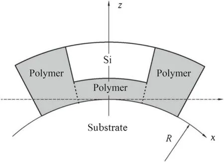
Fig.1 A typical structure of stickup flexible electronic system
2 Analytical model
In flexible electronics,electronic components are usually embedded in a soft,polymeric matrix.To achieve maximum flexibility,the brittle electronic components need to be placed at the neutral mechanical plane.Due to the periodic nature of the system,here we consider only a unit cell of a typical stickup flexible electronics structure which is shown in Fig.1.The composite structure consists of silicon(white area)and polymer(gray area),and is pasted on the surface of a curved substrate(with radius ofR).Due to the symmetry of the system,only half of the element needs to be analyzed,for which the cross section and geometric parameters are shown in Fig.2.Here,L1andLdenote the half lengths of the laminated region and entire unitcell,respectively;h1andhdenote the thicknesses of the bottom polymer and the unit cell,respectively.
Different from traditional laminated structures for flexible electronics,in the stickup structures shown in Figs.1 and 2,both the laminated region with dissimilar materials and the region with sole material should be analyzed.A Cartesian coordinate system is established,withxaxis along the horizontal direction andzaxis along the vertical direction,as shown in Fig.2.
In the laminated region(0<x<L1),the displacement field is given as

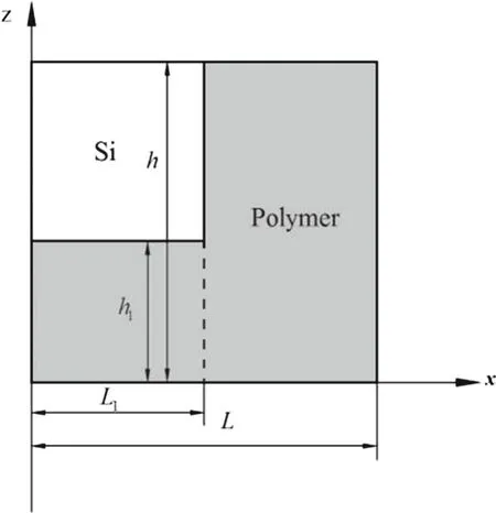
Fig.2 Geometrical parameters and coordinate system
whereθis the rotation angle;u,ware the piece-wise displacement along thexandzdirection,respectively.The first superscript of symbolurepresents the region 0<x<L1;while the second superscript represents the region 0<z<h1andh1<z<h,respectively.The polynomialsθiandw iare introduced up to the third-order in order to describe the parabolic variation of the shear stress across the transversal direction.Under the small deformation condition,the axial and shear strains can be obtained from the constitutive equations
By use of Hooke’s law,the normal stress and the shear stress can be written as

Taking into account the issue of transverse shear stress continuity,i.e.,τ(1,1)xz=τ(1,2)xzatz=h1,and zero transverse shear stress boundary condition at the top surface,i.e.,τ(1,2)xz=0 atz=h,we can get:


Substitute Eq.(6)into Eqs.(1)and(2),the displacement functions can be expressed as
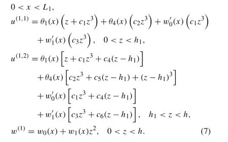
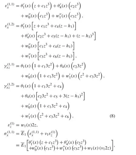
Based on the Eq.(7),the axial strains,shear strains,axial stresses,and shear stresses can be rewritten as
The displacement of regionL1<x<Lis modeled as a uniform function
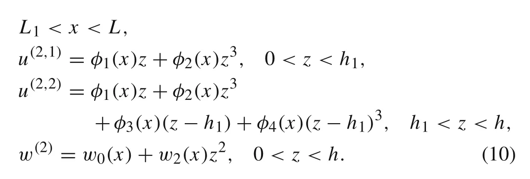
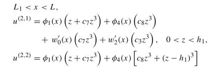
Similarly,considering continuous conditions of shearing stress and boundary conditions,τ(2,1)xz=τ(2,2)xzatz=h1,andτ(2,2)xz=0 atz=h,we can get the displacement functions in regionL1<x<Las the following

The displacement functions can be expressed as
The corresponding strains can be written as

The principle of virtual work for a beam is expressed as

Substituting Eqs.(8),(9),(13),and(14)into Eq.(15)and integrating by parts yields the following equations
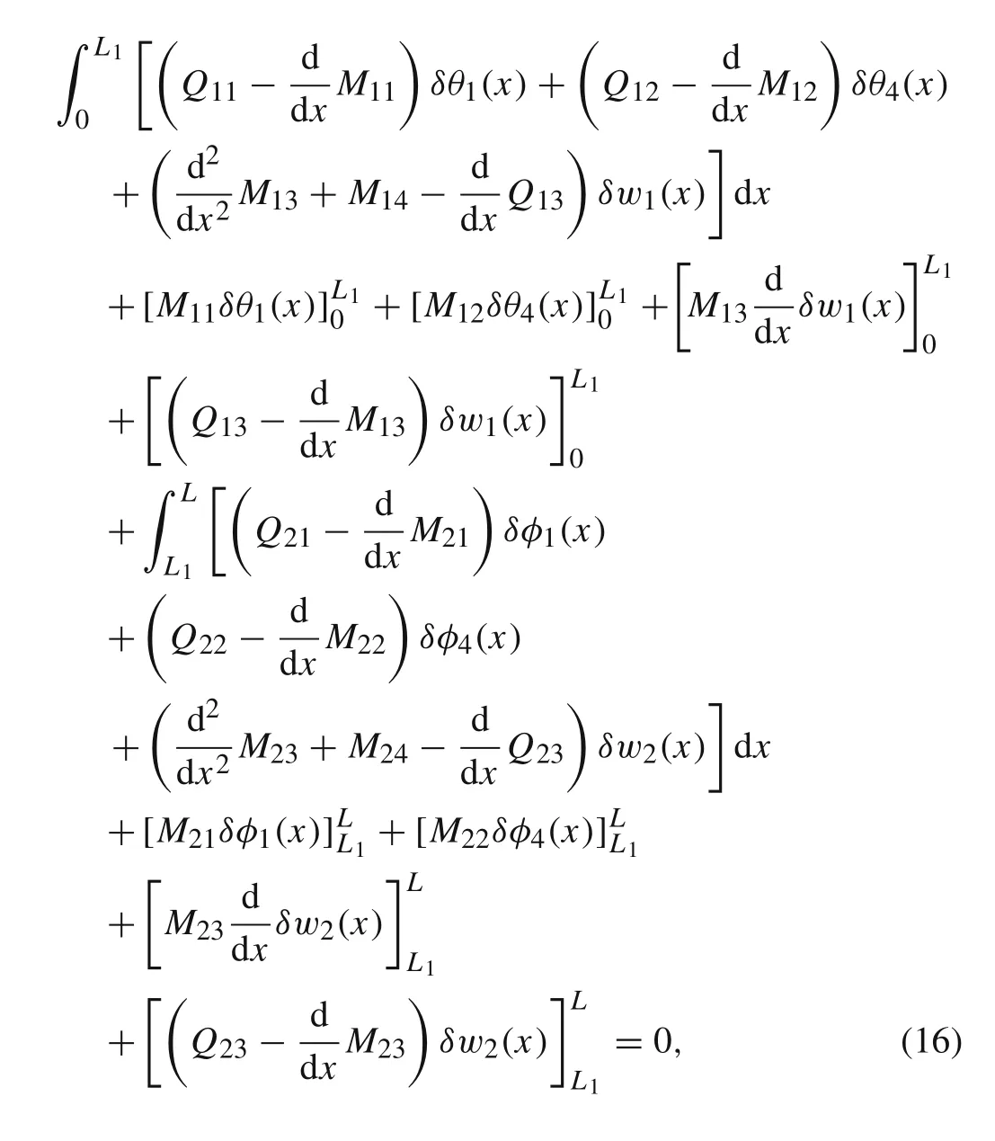
where the resultant moments and forces per unit width are
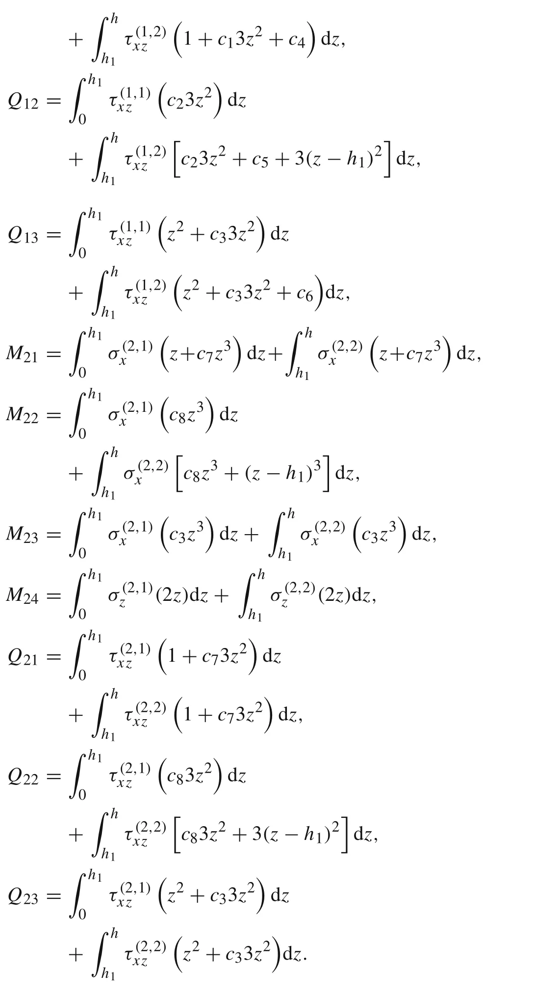
The governing differential equations can be obtained by equating the coefficients ofδθ1,δθ4,δw1,δφ1,δφ4,andδw2in Eq.(16)to zero:

and a consistent set of boundary conditions is obtained as
Substituting the expressions of stresses in Eqs.(9)and(14)into Eq.(17)yields the following equilibrium equations
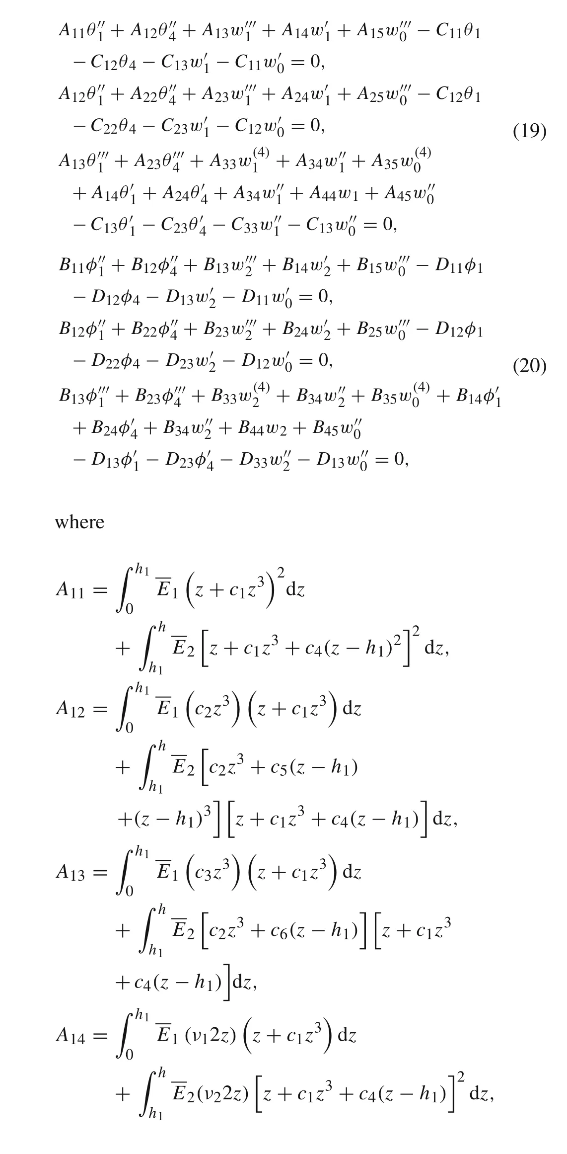


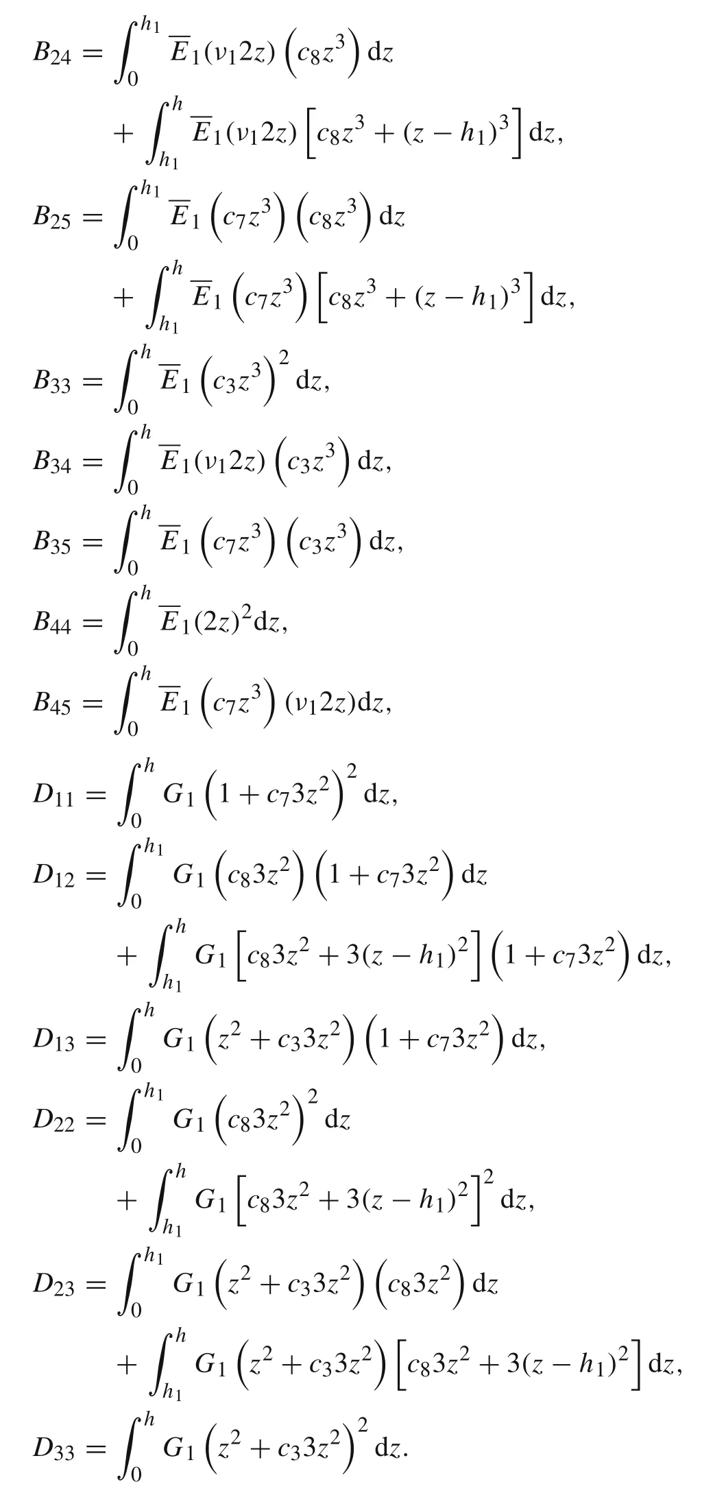
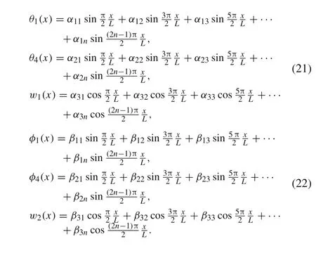
For the method of trigonometric series,the accuracy is high and application is simple[25].So the solutions ofθ1(x),θ4(x),w1(x),φ1(x),φ4(x),w2(x)are assumed to be a trigonometric series here.Substituting them into Eqs.(19)and(20),the final expressions can be determined as below.The number of termsncan be chosen according to the convergence of the final results.
3 Results and discussion
In this section,we investigate two cases of stickup structures:the Si-NOA system and the Si-PDMS system.The geometric parameters for the two systems areh1=20μm,h=40μm,L1=25μm,andL=50 μm.The material properties of the Si-NOA system areESi=150 GPa,νSi=0.27,ENOA=1 GPa,andνNOA=0.49.The material properties of the Si-PDMS system areESi=150 GPa,νSi=0.27,EPDMS=2 MPa,andνPDMS=0.48.The boundary conditions on

It is found in Figs.3–6 that the results from the theoretical analysis agree well with the FEA,and the analytical model is proved to be an effective method to analyze the stickup structure widely used in flexible electronics.The normal strain in silicon is rather small,and the polymer substrate isolates most of the applied strain.The peak value of shear stress occurs in the silicon material
Based on the above analysis,the effects of three typical parameters are discussed here:(1)different thickness ratio of the hard-soft layers;(2)different length ratio of the laminated area and the single material area;(3)different curvature of stickup substrate surface.The results are as shown as follows


From Figs.11–14 we can find that both the maximum normal strain and the maximum shear stress in the silicon increase with the increase ofΔL.

It is shown in Figs.15–18 that both the maximum normal strain and the maximum shear stress in silicon film increase with the increase of theΔw.
4 Conclusions
In this paper,a model of third-order polynomials is established to study the mechanics of multilayer hard-soft structures in stickup flexible electronics.Third-order polynomials are adopted to describe the displacement field,which is used to derive the strain and stress distributions.According to the analysis,the strain and stress distributions are similar between Si-NOA and Si-PDMS systems,and while the design parameters(Δh,ΔL,andΔw)are changed,the change of strains and stresses of these two systems present similar disciplines.
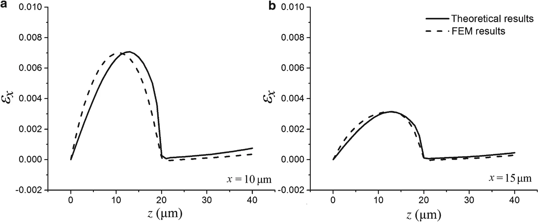
Fig.3 Normal strain distributions of the Si-NOA system
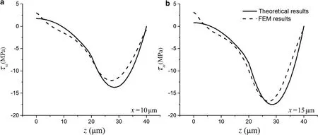
Fig.4 Shear stress distributions of the Si-NOA system

Fig.5 Normal strain distributions of the Si-PDMS system
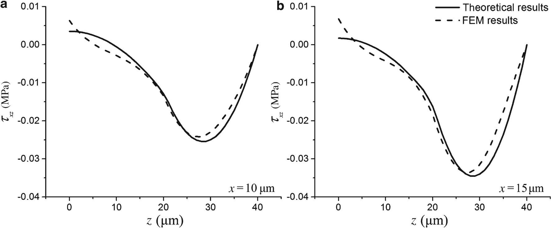
Fig.6 Shear stress distributions of the Si-PDMS system
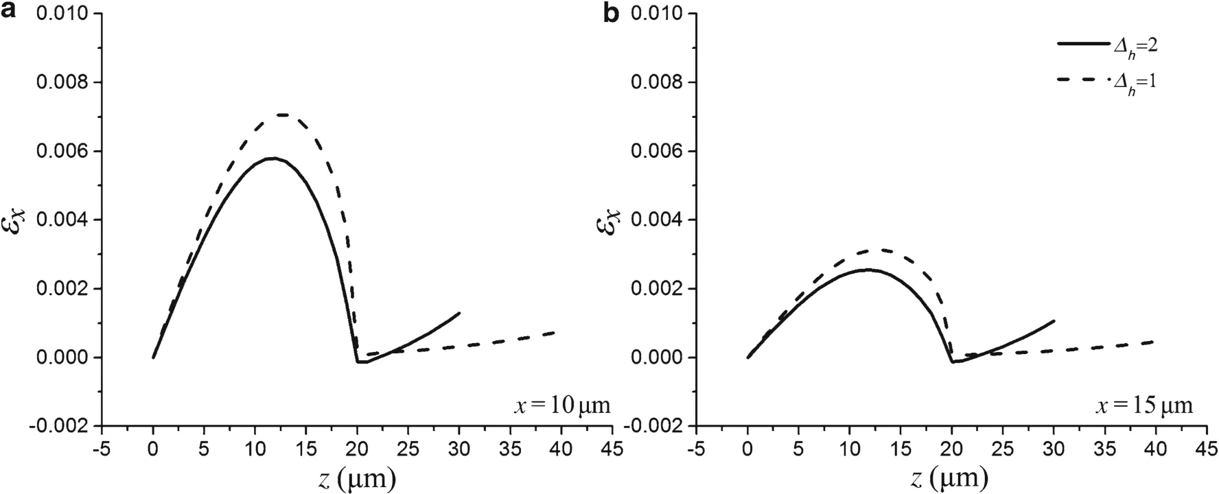
Fig.7 Normal strain distributions of the Si-NOA system with different thickness ratios
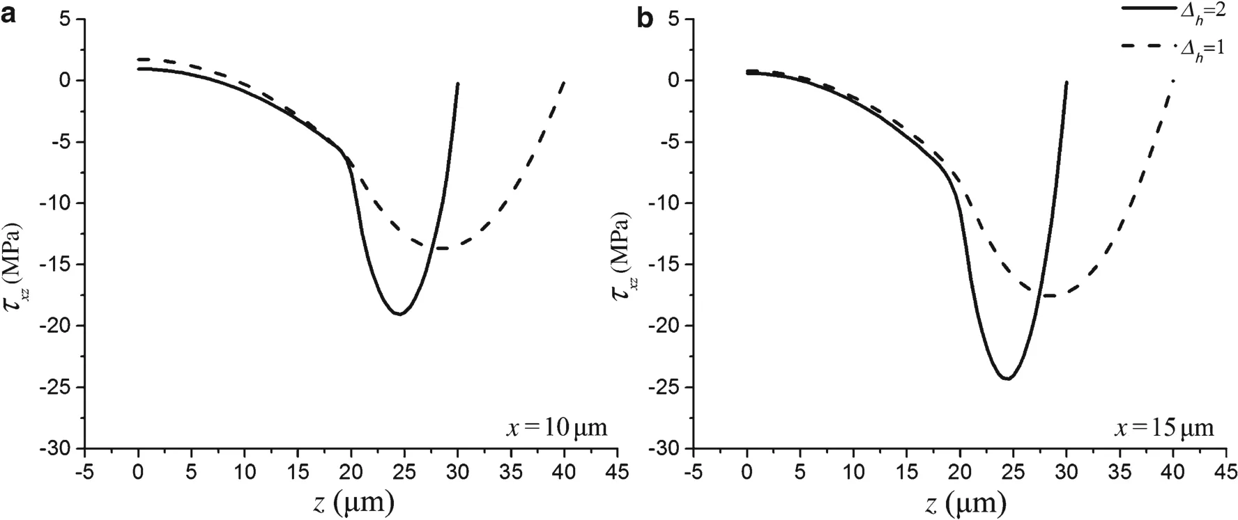
Fig.8 Shear stress distributions of the Si-NOA system with different thickness ratios
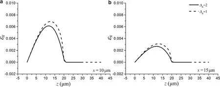
Fig.9 Normal strain distributions of the Si-PDMS system with different thickness ratios
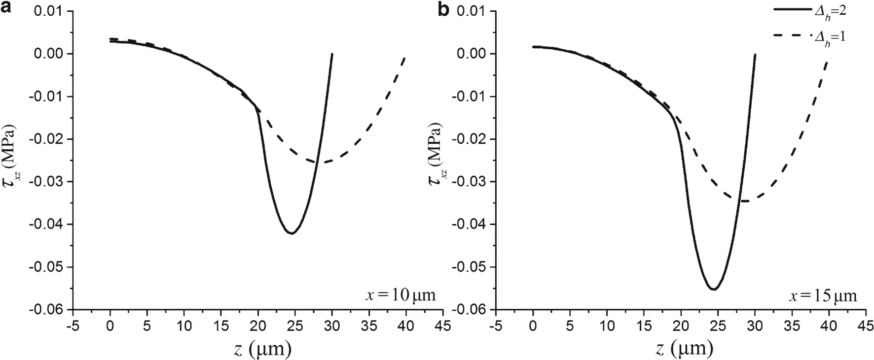
Fig.10 Shear stress distributions of the Si-PDMS system with different thickness ratios

Fig.11 Normal strain distributions of the Si-NOA system with different length ratios

Fig.12 Shear stress distributions of the Si-NOA system with different length ratios
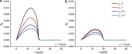
Fig.13 Normal strain distributions of the Si-PDMS system with different length ratios
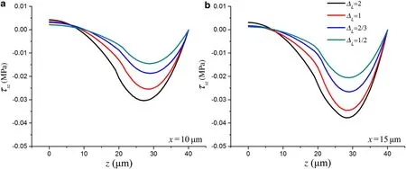
Fig.14 Shear stress distributions of the Si-PDMS system with different length ratios
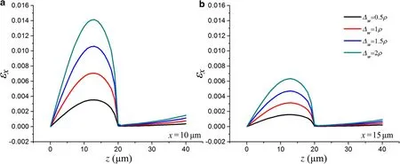
Fig.15 Normal strain distributions of the Si-NOA system with different curvatures
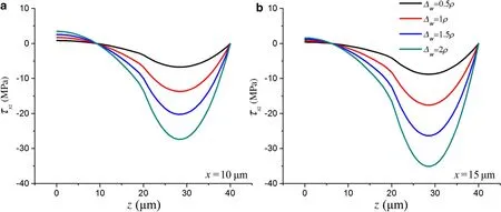
Fig.16 Shear stress distributions of the Si-NOA system with different curvatures

Fig.17 Normal strain distributions of the Si-PDMS system with different curvatures
The substrate accommodates the majority of the strain,so that the strain passed into the silicon is fairly small.For the shear stress,the maximum occurs at the silicon mate-rial,which may cause the shear failure of the structure.The shear stress at the interface is also very large,which may lead to delamination of the integrated structure.Therefore,the stress at the interface and inside the silicon material should be designed to be below the interfacial toughness to make sure that the structure can sustain large deformation.Furthermore,the effects of the geometric parameters are analyzed,which provide potential reference for the design and optimization of stickup flexible electronics in the future.
AcknowledgementsThe project was supported by the National Natural Science Foundation of China(Grants 11572022 and 11172022).
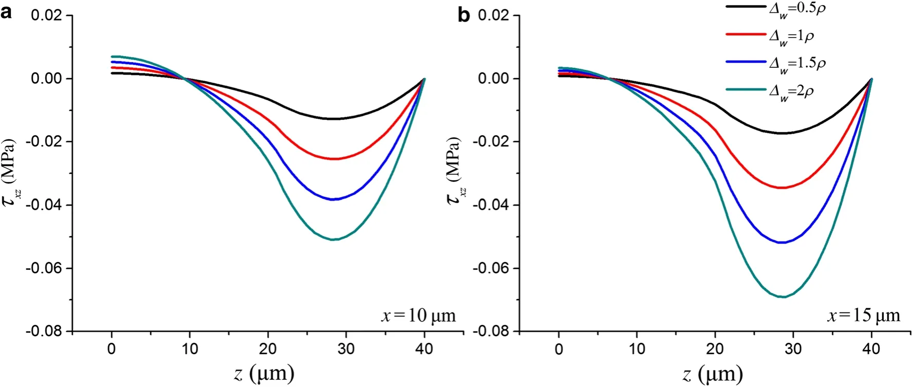
Fig.18 Shear stress distributions of the Si-PDMS system with different curvatures
1.Yoon,J.,Baca,A.J.,Park,S.I.,et al.:Ultrathin silicon solar microcells for semitransparent,mechanically flexible and micro concentrator module designs.Nat.Mater.7,907–915(2008)
2.Kim,D.H.:Epidermal electronics.Science 333,838–843(2011).doi:10.1126/science.1206157
3.Kim,D.H.,Lu,N.,Ghaffari,R.,et al.:Materials for multifunctional balloon catheters with capabilities in cardiac electrophysiological mapping and ablation therapy.Nat.Mater.10,316–323(2011)
4.Song,J.,Feng,X.,Huang,Y.:Mechanics and thermal management of stretchable inorganic electronics.Natl.Sci.Rev.3,128–143(2016)
5.Feng,X.,Lu,B.W.,Wu,J.,et al.:Review on stretchable and flexible inorganic electronics.Acta Phys.Sin.63,014201(2014).(in Chinese)
6.Tu,H.,Xu,Y.:Asilicon-on-insulator complementary-metal-oxide semiconductor compatible flexible electronics technology.Appl.Phys.Lett.101,182(2012)
7.Zhang,N.B.,Guo,Q.Q.,Yang,J.:The development of digital printing technologies for flexible electronics devices.Sci.Sin.46,044608(2016)
8.Kim,N.,Graham,S.:Development of highly flexible and ultra-low permeation rate thin-film barrier structure for organic electronics.Thin Solid Films 547,57–62(2013)
9.Ohishi,T.,Kawada,H.,Yoshida,T.,et al.:Development of a high performance flexible substrate for flexible electronics:joining TAC if lms and an ultra-thin Glassby using TEOS-DAC synthesized by the sol–gel method.Mater.Sci.Appl.06,1100–1110(2015)
10.Song,J.:Mechanics of stretchable electronics.Curr.Opin.Solid State Mater.Sci.19,160–170(2015)
11.Russo,A.,Ahn,B.Y.,Adams,J.J.,et al.:Pen-on-paper flexible electronics.Adv.Mater.23,3426–3430(2011)
12.Sun,Y.,Roger,J.A.:Inorganic semiconductors for flexible electronics.Adv.Mater.38,1897–1916(2007)
13.Lo,K.H.,Christensen,R.M.,Wu,E.M.:A high-order theory of plate deformation—part 1:homogeneous plates.J.Appl.Mech.44,663–668(1977)
14.Reddy,J.N.:Asimple higher-ordertheory for laminated composite plates.J.Appl.Mech.51,745–752(1984)
15.Reissner,E.:On asymptotic expansions for the sixth-order linear theory problem of transverse bending of orthotropic elastic plates.Comput.Methods Appl.Mech.Eng.85,75–88(1991)
16.Liu,D.,Li,X.:An overall view of laminate theories based on displacement hypothesis.J.Compos.Mater.30,1539–1561(1996)
17.Savithri,S.,Varadan,T.K.:Large deflection analysis of laminated composite plates.Int.J.Nonlinear Mech.28,1–12(1993)
18.Savithri,S.,Varadan,T.K.:Accurate bending analysis of laminated orthotropic plates.AIAA J.28,1842–1844(1971)
19.Sciuva,M.D.:An improved shear-deformation theory for moderately thick multilayered anisotropic shells and plates.J.Appl.Mech.54,589–596(1987)
20.Sciuva,M.D.:Multilayered anisotropic plate models with continuous interlaminar stresses.Compos.Struct.22,149–167(1992)
21.Sun,C.,Whitney,J.M.:Theories for the dynamic response of laminated plates.AIAA J.11,178–183(2012)
22.Carrera,E.:Historical review of Zig–Zag theories for multilayered plates and shells.Appl.Mech.Rev.56,287–308(2003)
23.Li,X.,Liu,D.:Zigzag theory for composite laminates.AIAA J.33,1163–1165(1995)
24.Tessler,A.,Sciuva,M.D.,Gherlone,M.:A refined zigzag beam theory for composite and sandwich beams.J.Compos.Mater.43,1051–1081(2009)
25.Zhu,Y.C.:Transcendence of certain trigonometric series.Acta Math.Sin.18,481–488(2002)
- Acta Mechanica Sinica的其它文章
- Amplitude modulation and extreme events in turbulent channel flow
- The influence of surface roughness on cloud cavitation flow around hydrofoils
- The influence of sub-grid scale motions on particle collision in homogeneous isotropic turbulence
- A simple algorithm to improve the performance of the WENO scheme on non-uniform grids
- A semi-analytical solution for electric double layers near an elliptical cylinder
- High-precision solution to the moving load problem using an improved spectral element method

