A method of elimination of undesired resonant points of microstrip antenna by cutting U-shaped slot on the ground
TENG Fei,CHENG Xiu-yang
(College of Electrical Engineering and Automation,Shandong University of Science and Technology,Qingdao 266590,China)
0 Introduction
With development of the microstrip antenna,circular polarization microstrip antenna has been wildly used because of the advantages of low profile[1],conformal,easy integration and low cost,etc..
In the Ref.[2],the author uses square patch and realizes circular polarization characteristics with cross slot,and axial ratio bandwidth of the circular polarization is 1.4%. In the Ref.[3],while perturbation method is used,the patch with corner cut realizes the circular polarization characteristics,and axial ratio bandwidth of the circular polarization is 1%. Here we design a dual-layer circular polarization microstrip antenna by cutting a rectangular aperture on the patch,but the antenna has some resonant points undesired. So we should eliminate these undesired resonant points by slotting on the ground[4,5].
1 Structure of designed antenna
The structure of designed antenna is shown in Fig.1. It's microstrip antenna of two layers medium. The purpose of cutting a rectangular aperture of 45°is to form a circular polarized wave. And sizes of the antenna are as follows:l1=89.23 mm,w1=89.23 mm,l2=20.87 mm,l3=14.6 mm,w2=4.84 mm,l4=19.8 mm,w3=1.8 mm,θ=45°,h1=1.6 mm,h2=1.87 mm.
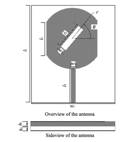
Fig.1 Structure of designed antenna
Based on the design,we use the electromagnetic simulation software to build up the antenna model and simulate. The simulation results are shown in Fig.2.
From Fig.2,we know that the frequency of the resonant point is 2.42 GHz. However,there are two undesired resonant points,the frequencies of which are both greater than the resonant frequency. One is around 4.4 GHz,the other is around 5.8 GHz.
Slotting with an appropriate size on the ground can generate high impedance at the corresponding frequency point. In the way,the conduction and radiation of the corresponding frequency wave can be suppressed,and the same way applies to the corresponding frequency. Thus,we eliminate the undesired resonant points by slotting on the ground.
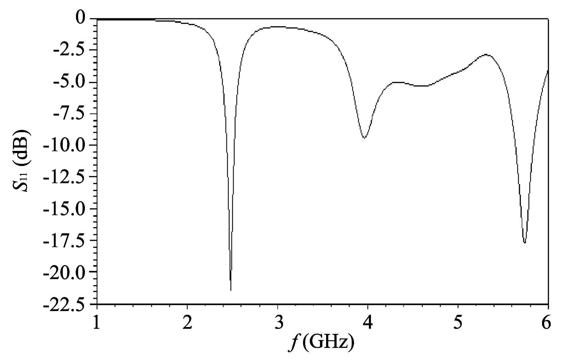
Fig.2 S11 of the antenna
2 Elimination of resonant frequency point of 5.8 GHz
In order to eliminate the resonant frequency point of 5.8 GHz,we open aU1-shaped slot on the ground of the antenna. Shape of the slot is shown in Figs.3-4.
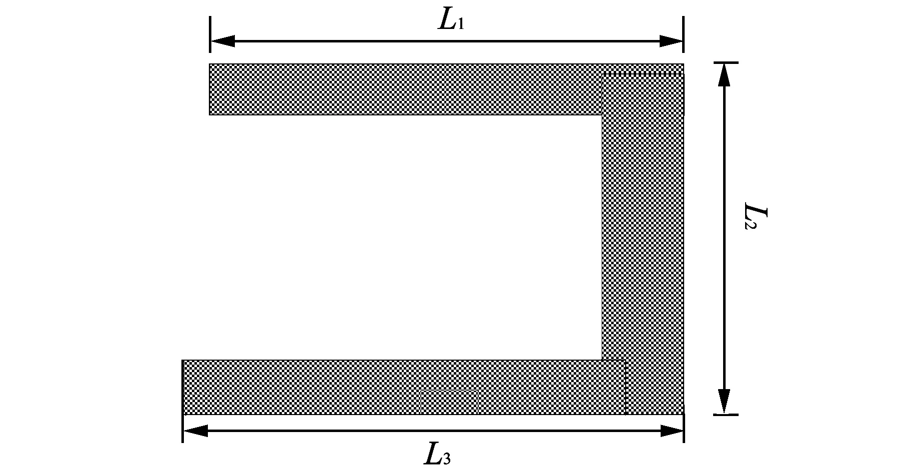
Fig.3 Diagram of U1-shaped slot on the ground
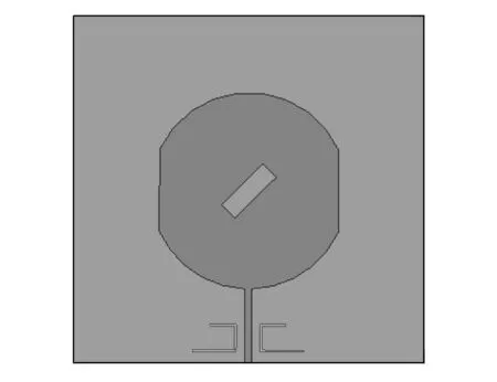
Fig.4 Diagram of slot on the ground of antenna
From the above analysis we know that the length of theU1-shaped slot is half of the wavelength of corresponding frequency point of 5.8 GHz,soL=L1+L2+L3=25 mm.
Based on the above design we use the electromagnetic simulation software to build up the antenna model and simulate. The simulation results are shown in Fig.5.
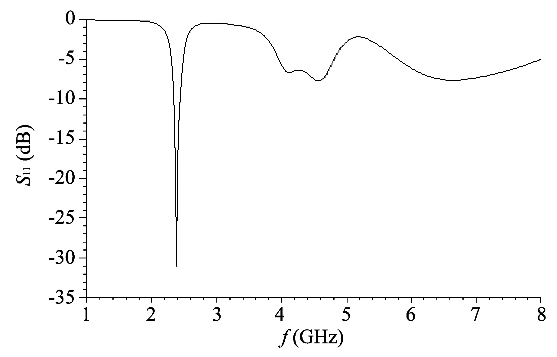
Fig.5 S11 inhibition of 5.8 GHz
From Fig.5 we know that the resonant point of 5.8 GHz can be inhibited greatest whenL=25 mm. The result of simulation is illustrated above. As shown in the Fig.5,the resonant depth at 5.8 GHz can be inhibited to -5 dB. So we eliminate the resonant frequency point of 5.8 GHz by cutting aU1-shaped slot on the ground.
3 Elimination of resonant frequency point of 4.4 GHz
Similarly,in order to eliminate the resonant frequency point of 4.4 GHz,we open aU2-shaped slot shown in Fig.6 on the ground of the antenna.
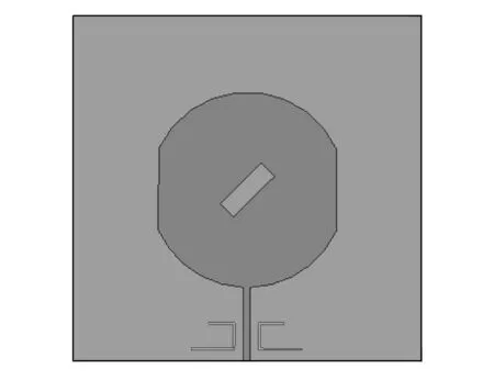
Fig.6 Diagram of U2-shaped slot on the ground
In the same way,length of theU2-shaped slot is half of the wavelength of corresponding frequency point of 4.4 GHz,soL′=L4+L5+L6=37 mm,and the simulation results are shown in Fig.7.
From the results we know that the resonant depth at 4.4 GHz can be inhibited to -7 dB. So theU2-shaped slot opened on the ground can eliminate resonant frequency point of 4.4 GHz effectively.
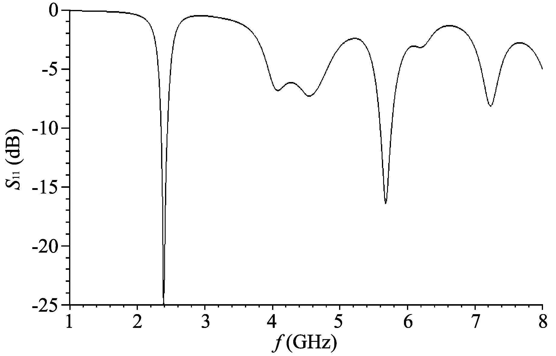
Fig.7 S11 inhibition of 4.4 GHz
4 Conclusion
In this paper,we propose a method to eliminate undesired resonant points of designed microstrip antenna by cuttingU- shaped slots on the ground. In the wayS11of 4.4 GHz and 5.8 GHz are both greater than -10 dB,so the undesired resonant frequency points of 4.4 GHz and 5.8 GHz can be eliminated effectively.
[1] ZHONG Shun-shi. Microstrip antenna theory and application. Xi 'an: Xi'an University of Electronic Science and Technology Press,1991.
[2] CHEN Wen-shyang,WU Chun-kun,WONG Kin-lu. Novel compact circularly polarized square microstrip antenna. IEEE Transactions on Antennas Propagation,2001,49(3): 340-341.
[3] WONG Kin-lu,WU Jian-yi. Sing-feed small circularly polarized square microstrip antenna. Electronics Letters,1997,33(22): 1833-1834.
[4] Zolfagharian A R,Azarmanesh M N,Qjaroudi M. Ultra wide band small square monopole antenna with variable frequency notch ban characteristics. Microwave and Optical Technology Letters,2012,54(1): 262-267.
[5] WONG Kin-lu,LIN Yi-fang. Circularly polarized microstrip antenna with atuning stub. Electronics Letters,1998,34(9): 831-832.
 Journal of Measurement Science and Instrumentation2014年2期
- Journal of Measurement Science and Instrumentation的其它文章
- Application of Kalman filter on mobile robot self-localization
- Design of a titl angle measurement system based on ADXL345 sensor
- Status and development trend of asphalt foaming process
- Research and simulation of two-level grid-connected photovoltaic inverter system
- Research on temperature control module of injection molding machine based on C8051F020
- Design and application of integrated automation system platform of mine based on PON
