The Kinetics for Electrochemical Removal of Ammonia in Coking Wastewater*
LIANG Zhenhai (梁鎮(zhèn)海)**, LI Su (李素), GUO Wenqian (郭文倩) and FAN Caimei (樊彩梅)
College of Chemistry and Chemical Engineering, Taiyuan University of Technology, Taiyuan 030024, China
1 INTRODUCTION
Coking plant is one of the industries causing environmental pollution in China. So far many methods are used to treat wastewater such as membrane-less microbial fuel cell (ML-MFC) was designed for wastewater treatment and so on [1]. The composition of wastewater is complicated and it always contains high concentration of ammonia, phenols, cyanide and other aromatic organics which have serious effect to environment [2]. Most of the substances are bio-toxical and the traditional activated sludge degradation process fails to eliminate chemical oxygen demand (COD)[3], ammonia and color [4]. For example, ammonia can cause promotion of eutrophication which is fatal to aquatic lives, hinder disinfection of water supplies,and have an offensive smell and carcinogenesis [5].
The electrochemical oxidation processes have attracted great interests recently. The electrochemical method has been successfully employed to destroy a variety of pollutants such as ammonia, nitrite [6],chlorophenols [7], dyes [8] and so on. But there were few reports about the electrochemical removal of ammonia in coking wastewater except for Chianget al.[9], who found that this technique is feasible for treating coking plant wastewater, and showed the removal of the pollutants in electrochemical oxidation process is mainly attributed to the indirect oxidation of chiorine/hypochlorite. In this paper, we focus the efforts on the derivation of the reaction mechanism for electrochemical removal of ammonia in coking wastewater and its confirmation by experiments.
2 EXPERIMENTAL
2.1 Instruments and reagents
VMP3-Multi potentiostat electrochemical station(Princeton Applied Research Instruments, USA) was used to get cyclic voltammograms (CV). All reagents were analytical grade. The solutions were prepared with fresh double-distilled and deionized water.
2.2 Electrochemical experiments
The detail of the preparation method of the anodes can be found in Ref [10]. An X-ray diffractometer D/Max-IIIA (Rigaku Co.Japan) using CuKα1 (λ=0.154056 nm) as radiation source was used for identification of the phases [11].
Three-electrode system is used in the CV experiment. Ti/SnO2+Sb2O4/PbO2electrode (1.0 cm×1.0 cm) was used as the working electrode, and a Pt counter electrode (1.0 cm ×1.0 cm) and an SCE (Saturated calomel electrode) reference electrode were employed for the experiments. The anolyte was 0.1 mol·L-1NaCl solution containing 0.1 mol·L-1(NH4)2SO4. The pH was adjusted by NaOH and H2SO4. The effect of scanning rate is discussed. All the experiments were carried out at room temperature.
3 RESULTS AND DISCUSSION
3.1 Electrooxidation of ammonia
3.1.1Effect of sweep rate
According to the elementary potential of the basic reactions.

in the acidic solution (ammonium sulfate solution was weakly acidic),

The influence of the sweep rate on the cyclic voltammetry behavior of the Ti/SnO2+Sb2O4/PbO2electrode in the same concentration of ammonia is shown in Fig. 1. As the sweep rate increases, the anodic peak potentials shift to more positive when the sweep rate from 5 mV·s-1to 100 mV·s-1, which showed that ammonia electro-oxidation reaction on the Ti/SnO2+Sb2O4/PbO2electrode is irreversible process. The oxygen absorption peak appeared when the sweep rate is 5 mV·s-1.However, with the sweep rate increase the oxygen absorption peak becomes less obvious, which means that the scan rate so fast that it doesn’t match with the current response. The reaction of O2evolution begins to occur when the sweep rate increases further.The deposition potential of O2is similar with Cl2(=1.229 V,=1.35827 V), so that the oxidation peaks of them will overlap. From Fig. 1 we also can see that the initial anodic peak potential of nitrogen is slightly larger thanφN2/NH+4in the theory due to the overpotential exists. So all the results showed good agreement with Kim’s [5] report that ammonia was oxidized to nitrogen finally.
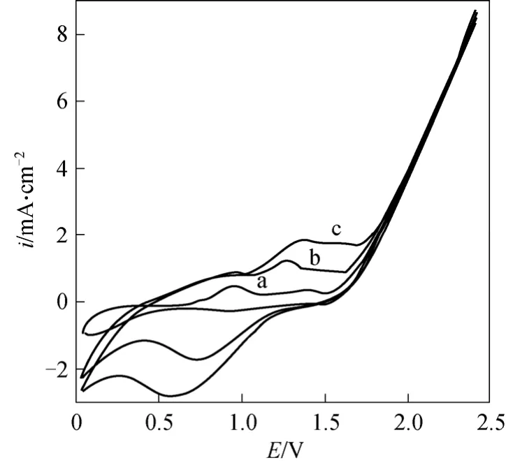
Figure 1 The cyclic voltammetry curves at different sweep ratea—5 mV·s-1; b—50 mV·s-1; c—100 mV·s-1, pH=5, electrolyte containing 0.10 mol·L-1 NaCl and 250 mg·L-1 (NH4)2SO4
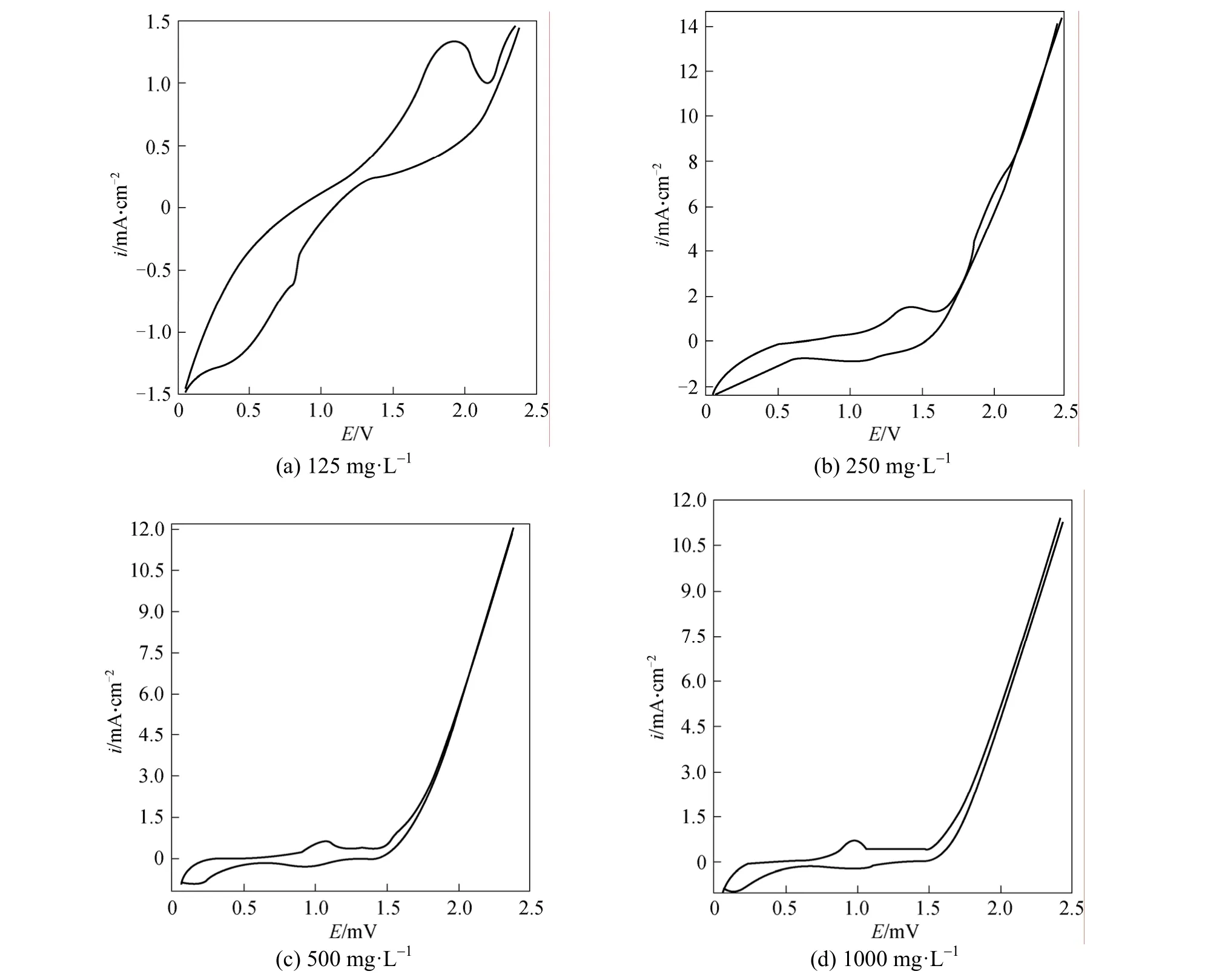
Figure 2 The cyclic voltammetry curves in different concentration of ammoniapH=5, electrolyte containing 0.10 mol·L-1 NaCl and different concentration of (NH4)2SO4
3.1.2Effect of ammonia concentration
In order to further clarify the mechanism of electrochemical oxidation of ammonia on the Ti/SnO2+Sb2O4/PbO2electrode, the effect of ammonia concentration on cyclic voltammetry was investigated. It is shown from Fig. 2 that anodic peak is evident before oxygen evolution potential is reached, which indicated obvious catalytic oxidation of ammonia on the Ti/SnO2+ Sb2O4/PbO2electrode. The oxidation peak appeared at 1.6 V, 1.3 V, 1.01 V, 0.9 V when the concentration of ammonia are 125, 250, 500, 1000 mg·L-1respectively. With the ammonia concentration increases, the anodic peak potential shifts to less negative. The current density is the largest when the concentration is 250 mg·L-1, but as the concentration increases to 500 mg·L-1and 1000 mg·L-1, the current density decreases. So the electrochemical method is more suitable to deal with ammoniacal nitrogen wastewater of low concentration.
3.2 Reaction mechanism
3.2.1The assumed mechanism
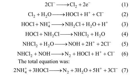
The reaction mechanism of the electrode was assumed as [5, 9]:
3.2.2The parameter of the electrode process
According to the stable polarization curve of anode from Fig. 3, the anodic Tafel slope was So the anodic apparent transport coefficient wasaα=1.5.

According to the stable polarization curve of cathode from Fig. 4, the cathodic Tafel slope was
So the cathodic apparent transport coefficient wasαc= 0 .5.
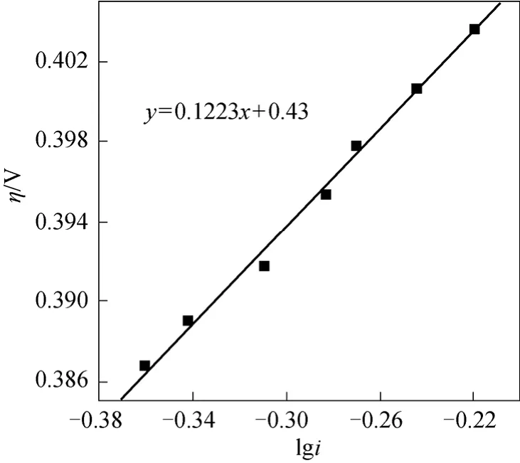
Figure 4 Stable polarization curves of cathode
The stochiometric number of rate-determining step was obtained fromαc,αaand the fact that oxidation of4NH+to N2with 6 electrons lost:

The electrochemical reaction order of4NH+was obtained by the effect of the concentration of4NH+to stable polarization curve according to Fig. 5:

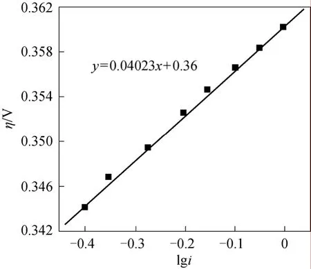
Figure 3 Stable polarization curves of anode
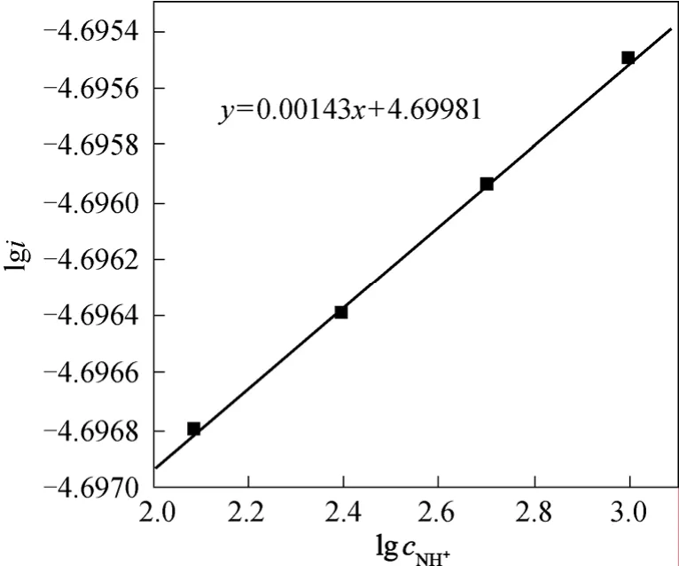
Figure 5 The relationship between l g c N H+4 and lgi
The electrochemical reaction order of Cl-was gained according to the stable polarization curve from Fig. 6:

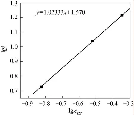
Figure 6 The relationship between l g cC l- and lgi
3.2.3The derivation of electrocatalytic mechanism
The kinetics relationship of electrode reaction can be deduced by a steady-state approach or a quasi-equilibrium approach in the stable condition. If there were only one rate-determining step in a multi-step reaction process, the quasi-equilibrium approach is convenient [12].
If step (1) was assumed as the rate-determining step, the relationship between current density and potential would be

Because step (2) wasn’t the rate-determining step, it was in equilibrium:

According to Eq. (14), we get

Using the same method we get:

The electrode potential was assumed positive enough to balance electrode potential. Whenη≥120/n(mV), the cathode reaction can be neglected, and the current density of anodic reaction was
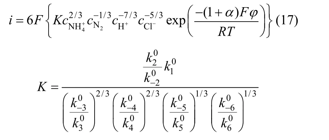
We can see that the electrochemical reaction order of4NH+ion was 2/3 from Eq. (17) but from experiment the order was 0. The discrepancy indicated the first step wasn’t the rate-determining step.
The second step was then assumed as the ratedetermining step, and the relationship between current density and potential was

The followed derivation can be gotten with same method:

Supposing the electrode potential was Positive enough opposite to balance electrode potential. Whenη≥120/n(mV), the cathode reaction can be neglected,and the current density of anodic reaction was
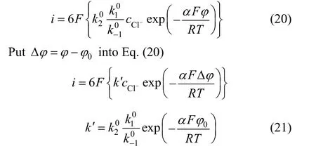
When 0.5α=,T=25 °C, the cathode reaction Tafel

The stochiometric number of the rate-determining step was counted according to Eq. (10):

The electrochemical reaction order of Cl-and4NH+were counted according to Eq. (19):
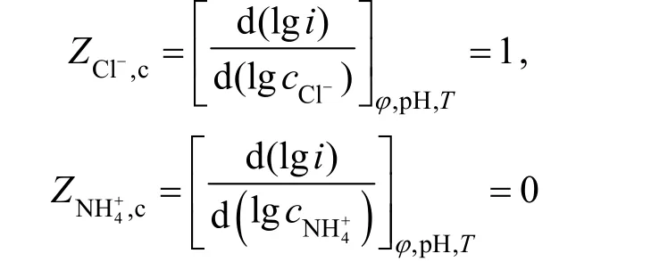
Kinetics equation was derived from the assumed reaction mechanism theoretically. Then the electrochemical reaction order, apparent transfer coefficient,Tafel slope and chemical measurement data were calculated from the kinetic equation. The theoretical data and the experimental data are consistent. So the assumed reaction mechanism was right and the second step was controlled step.
3.2.4Confirmation of the control step
The apparent transfer coefficient of cathode and anode was calculated by

respectively. The values ofγ,v, andrwere got from the assumed mechanism andαwas assumed as 0.5.The calculation was detailed as follows:
When the second step was the controlling step,γ=0,v=3,r=1. Soαc=0.5,αa=1.5. The calculated results of apparent transfer coefficient was equal to the experimental values. So the reaction mechanism was confirmed.
4 CONCLUSIONS
The electrolytic oxidation of ammonia on Ti/SnO2+Sb2O4/PbO2electrode was identified to be an irreversible process. The reaction mechanism was determined by a quasi-equilibrium state method. The assumed reaction mechanism of electrochemical oxidation mechanism and the controlling step Cl2+H2O→ HOCl + H++Cl-were confirmed to be consistent with the experiments.So the oxidation of HOCl was an important step in the process of electrochemical removal of ammonia.
NOMENCLATURE
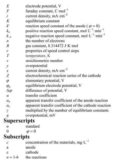
cconcentration of the materials, mg·L-1
1 Du, Z.W., Li, Q.H., Tong, M., Li, S.H., Li, H.R., “Electricity generation using membrane-less microbial fuel cell during wastewater treatment”,Chin.J.Chem.Eng., 16 (5), 772-777 (2008).
2 Minhalma, M., de Pinho, M.N., “Integration of nanofiltration/steam stripping for the treatment of coke plant ammoniacal wastewaters”,J.MembranlSci., 242, 87-95 (2004).
3 Shen, J.Y., He, R., Wang, L.J., Han, W.Q., Li, J.S., Sun, X.Y., “Kinetics of COD removal in a biological aerated filter in the presence of 2,4,6-trinitrophenol (picric acid)”,Chin.J.Chem.Eng., 17 (6),1021-1026 (2009).
4 Ning, P., Hans-J?rg, B., Jiang, Y.J., “Treatment of organic pollutants in coke plant wastewater by the method of ultrasonic irradiation,catalytic oxidation and activated sludge”,Sep.Purif.Technol., 41,133-139 ( 2005).
5 Kim, K.W., Kim, Y.J., Kim, I.T., Park, G.I., Lee, E.H. “The electrolytic decomposition mechanism of ammonia to nitrogen at an IrO2anode”,Electrochim.Acta, 50, 4356-4364 (2005).
6 Lin, S.H., Wu, C.L., “Electrochemical removal of nitrite and ammonia for aquaculture”,Water Res., 30 (3), 715-721 (1996).
7 Polcaro, A.M., Palmas, S., “Electrochemical oxidation of chlorophenols”,Ind.Eng.Chem.Res., 36, 1791-1798 (1997).
8 Szpyrkowicz, L., Juzzolino, C., Kaul, S.N., Daniele, S., “Electrochemical oxidation of dyeing baths bearing disperse dyes”,Ind.Eng.Chem.Res., 39, 3241-3248 (2000).
9 Chiang, L.C., Chang, J.E., Wen, T.C., “Indirect oxidation effect in electrochemical oxidation treatment of landfill leachate”,WaterRes.,29 (2), 671-678 (1995).
10 Jin, S.X., Ye, S.Y., “Oxygen evolution on titanium anodes coated with conductive metallic oxides: kinetics and mechanism in alkaline solution”,Electrochim.Acta, 41(6), 827-834 (1996).
11 Montilla, F., Morallón, E., de Battisti, A., Benedetti, Y.H., Vázauez,J.L., “Preparation and characterization of antimony-doped tin dioxide electrode. Part 2. XRD and EXAFS characterization”,J.Phys.Chem.B, 108, 5044-5050 (2004).
12 Wu, H.H., Applied Electrochemistry Foundation, Xiamen University Press, Xiamen, 80-87 (2006). (in Chinese)
 Chinese Journal of Chemical Engineering2011年4期
- Chinese Journal of Chemical Engineering的其它文章
- Adsorptive Recovery of Uranium from Nuclear Fuel Industrial Wastewater by Titanium Loaded Collagen Fiber*
- Salting-out Extraction of 2,3-Butanediol from Jerusalem artichoke-based Fermentation Broth*
- Investigation of Mg2+/Li+ Separation by Nanofiltration*
- Vapor-Liquid Equilibrium of Ethylene + Mesitylene System and Process Simulation for Ethylene Recovery*
- Purification and Characterization of a Nonylphenol (NP)-degrading Enzyme from Bacillus cereus. Frankland*
- Sponge Effect on Coal Mine Methane Separation Based on Clathrate Hydrate Method*
