Jet formation and penetration performance of a double-layer charge liner with chemically-deposited tungsten as the inner liner
Bihui Hong , Wenin Li ,*, Yiming Li , Zhiwei Guo , Binyou Yn
a Ministerial Key Laboratory of ZNDY, Nanjing University of Science and Technology, Nanjing 210094, China
b State Key Laboratory of Explosion Science and Technology, Beijing Institute of Technology, Beijing 100081, China
c Xiamen Tungsten Co., Ltd., Xiamen 361004, China
Keywords:Shaped charge Chemical vapor deposition Tungsten Double-layer charge liner X-ray Penetration
ABSTRACT This paper proposes a type of double-layer charge liner fabricated using chemical vapor deposition(CVD)that has tungsten as its inner liner.The feasibility of this design was evaluated through penetration tests.Double-layer charge liners were fabricated by using CVD to deposit tungsten layers on the inner surfaces of pure T2 copper liners.The microstructures of the tungsten layers were analyzed using a scanning electron microscope (SEM).The feasibility analysis was carried out by pulsed X-rays, slug-retrieval test and static penetration tests.The shaped charge jet forming and penetration law of inner tungsten-coated double-layer liner were studied by numerical simulation method.The results showed that the doublelayer liners could form well-shaped jets.The errors between the X-ray test results and the numerical results were within 11.07%.A slug-retrieval test was found that the retrieved slug was similar to a numerically simulated slug.Compared with the traditional pure copper shaped charge jet, the penetration depth of the double-layer shaped charge liner increased by 11.4% and >10.8% respectively.In summary, the test results are good, and the numerical simulation is in good agreement with the test,which verified the feasibility of using the CVD method to fabricate double-layer charge liners with a high-density and high-strength refractory metal as the inner liner.
1.Introduction
Shaped-charge warheads are commonly used on the battlefield for a variety of armor-piercing applications.These warheads operate under the principle that, when the liner is compressed during detonation,a high-temperature,high-pressure,and high-speed jet is formed.This jet converts the chemical energy of the explosive into kinetic energy of the liner,which causes damage to the target[1-3].To achieve high-performing warheads, many studies have examined warhead designs that include new materials, new processes, or new structure types [4-6].Double-layer liners perform better than single-layer liners in terms of energy absorption and conversion because they use refractory metals with high densities and strengths that have excellent ductility.Thus, double-layer liners have significant advantages and are currently a popular research topic [7-12].
Recently, most studies regarding double-layer charge liners have focused on optimizing common and easy-to-machine materials using numerical simulations in order to achieve the best penetration performance through an optimal combination of the inner and outer liners.For instance, several studies [13-15]analyzed the effects of various outer-liner materials on the jet formation of double-layer charge liners.The results showed that the material can significantly influence the jet quality, that is, the penetration performance.In addition to using numerical simulation methods, many studies also developed liners for physical experiments and explored the penetration effect of each.Huang et al.[16] designed a double-layer charge liner based on the K-charge and studied its jet formation and penetration performance.The results showed that the double-layer charge liner formed a continuous jet and had a promising penetration performance with respect to a target plate.Sun [17] studied the jet formation mechanism and penetration characteristics of double-layer charge liners and found that when the outer liner was made of metal, the jet exhibited a better penetration performance and a greater penetration depth.According to the Hill-Mott-Pack density law[18],when the outer liner is made of a metal with a low density,the inner liner should have a high density and good ductility[19];these characteristics enable the formation of a jet with high density that can achieve good penetration results.However, for refractory metals with large density values and high strengths,manufacturing charge liners using traditional machining processes is challenging.Therefore, few studies have investigated high-strength refractory metals such as tungsten; this lack severely hinders double-layer charge liner development.
Chemical vapor deposition(CVD)is the process of using gaseous or vaporous substances to conduct chemical reactions on a solid phase or a gas-solid interface to form solid deposits [20].It has recently been used in some studies to prepare single-layer tungsten shaped charge liners [21-23].In these studies, CVD systems were optimized to prepare large-caliber tungsten charge liners with improved wall thickness, density, and grain size properties, which to a certain extent improved the penetration performance of the tungsten liners.However, these studies only focused on singlelayer tungsten charge liners; few scholars have studied doublelayer charge liners.It is a novel concept to use CVD to prepare the inner liner of a double-layer liner using a high-strength, highdensity refractory metal.This method has great potential for advancing the research and application in the armor-penetration field.
Therefore, experimental analyses and numerical simulations were conducted during this study to investigate using CVD during the fabrication of double-layer charge liners and to evaluate the jet formation and penetration performance of the resultant liners.Specifically,using CVD to make double-layer liners.With tungsten as the inner material was proposed.The feasibility of the proposed method was verified through pulsed X-rays, retrieval tests, static penetration tests, and numerical simulations which provided valuable technical information for the preparation of double-layer charge liners.
2.Jet formation and fabrication principle
2.1.Jet formation principle
The formation of the penetrating body of a shaped charge is a complex physical and chemical process accompanied by substantial energy conversion.An explosive produces a detonation pressure which can crush the charge liner within a dozen microseconds.Since the detonation pressure far exceeds the yield strength of the liner material, the liner material can be regarded as a non-viscous incompressible fluid.In high-temperature, high-pressure, highstrain, and high-strain-rate conditions, when the thicknesses of the two charge liner layers are similar, the difference between the velocities of the micro-elements in the two layers can be ignored in the thickness direction,that is,there is no relative motion between the two liners;therefore,they can be regarded as a single element[8].Traditional shaped charges have single-layer liners, and the detonation pressure causes the internal and external materials to form a jet and a slug, respectively.The mass of the jet material accounts for 15% of the total charge liner mass [24,25].The utilization rate of the liner is very low during the forming process.In contrast, double-layer charge liners improve the charge liner utilization rate and reduce the occurrence of slug blockage during the penetration process.
Generally, double-layer charge liner jet formation can be divided into three types, as shown in Fig.1.For the first type, the inner liner is completely converted into a jet,while the outer liner is converted into a slug.The inner liner of the second type is also completely converted into a jet, and a small amount of the outer liner also becomes part of the jet.For the third type, the complete outer liner, as well as part of the inner liner, forms a slug.
Materials with large density values, high sound velocities, high melting points, and high ductility values are optimal for the inner liner.According to the Hill-Mott-Pack density law [18], a greater effective jet density leads to better ductility and a better penetration performance.Tungsten is a common high-density material.However, it also has a high strength and is refractory; these properties cause difficulty when manufacturing tungsten charge liners,especially double-layer charge liners.
According to the jet formation mechanism of double-layer charge liners, the tungsten in the inner liner had a large density and thus a good penetration capability.Therefore, as much of the tungsten as possible should be converted to the jet.However, the tungsten had poor ductility and was prone to causing jet fracture due to the large velocity gradient, which significantly affected its penetration capability.Hence,it was combined with copper,which had better ductility, to improve the jet ductility and reduce the likelihood of jet fracture.Therefore,to study the jet formation and penetration performance of tungsten-coated double-layer charge liners, the inner tungsten-coated double-layer liner was prepared by CVD and verified by experiments.To explore the application prospect of inner tungsten-plated double-layer liner in the field of armor breaking.
2.2.Fabrication of double-layer charge liners
2.2.1.Geometric model
A geometric model of the double-layer charge liner investigated during this study is shown in Fig.2.In the figure,D represents the charge diameter, H is the charge length, the aspect ratio, L/D, is equal to 1.3, and the charge used was an 8701 explosive.The liner has a frustum structure with a flat top, its taper angle is 2α, the thicknesses of the outer and inner layers are represented by δ1and δ2,respectively,and the thickness ratio is defined as η=δ2/δ1.Point detonation was used for the simulations,and the detonation point was located at the center of the top of the charge.
2.2.2.Fabrication of liners using CVD
To explore the feasibility of using CVD to fabricate double-layer liners with high-density refractory tungsten as the inner liners and to evaluate their jet formation and penetration performance, two double-layer charge liners, namely,1.0Cu-0.2W and 1.0Cu-0.3W,were created during this study.Between,1.0Cu indicates that the thickness of Cu layer is 1 mm,and 0.2W indicates that the thickness of W layer is 0.2 mm.
CVD is essentially a multiphase chemical reaction at the gas-solid interface.The mixed gas in the deposition reaction flows to the deposition area,then the reactant molecules are adsorbed by the deposition surface and react on or near the surface to form crystals and gas by-products.The crystals form a lattice through surface diffusion,while the gas by-products are desorbed from the surface and discharged from the deposition area along with the reactant molecules that did not react[22,26].During the deposition process, the H2in the mixed gas reduces the WF6and generates a series of intermediate products, WFn.As the reaction progresses,the H2reacts with the WFnto generate elemental tungsten.The reduction reaction of WF6by H2is shown in Fig.3 [23].

Fig.1.Different types of jets formed by double-layer charge liners [19].
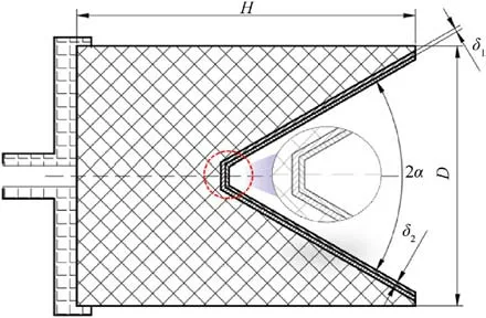
Fig.2.Geometric model of a double-layer charge liner.

Fig.3.Reaction equation for the CVD process.
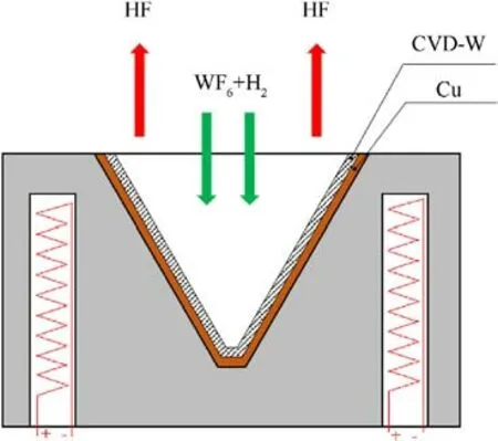
Fig.4.Schematic diagram of using CVD to coat the inner wall of a T2 copper liner with tungsten.
Based on the geometric model shown in Fig.2,a T2 copper bar was machined to obtain a liner with a taper angle of 60°.To improve the deposition efficiency, the inner surface of the T2 copper liner was polished with 2000 mesh sandpaper and then cleaned with water and alcohol.After the T2 copper liner had been cleaned and dried, the liner and the deposition system were assembled (Fig.4) and placed in the CVD equipment.The equipment was heated under the protection of hydrogen.After the temperature of the inner wall of the T2 copper liner reached 500°C,it was maintained for 60 min to ensure that the liner was heated evenly.Subsequently,WF6and H2were introduced to start the CVD process.The flow rates of the WF6and H2were set to 1 L/min and 3 L/min, respectively.The deposition thickness was controlled by adjusting the deposition time.Double-layer charge liners with 0.3-mm and 0.4-mm inner-liner deposition thicknesses were obtained after 30 min and 40 min of deposition, respectively.
The uniformity of the inner surface of the tungsten layer significantly influences the liner performance.The inner surface of the double-layer liner was not uniform after deposition; rather, it contained tungsten particles of various sizes.An analysis performed with a scanning electron microscope (SEM) showed that the largest particles reached 135 μm.If the inner surface was not treated,the jet shape would be adversely affected,thereby reducing the stability of the metal jet and its armor-penetration capability.Therefore, the inner surfaces of the "inner surface CVD-W + T2"double-layer liners with 0.3-mm and 0.4-mm inner-liner deposition thicknesses were polished to obtain high-quality jets.Fig.5 depicts the inner wall of the double-layer liner before and after polishing.The surface conditions are shown in Fig.5.The wall thickness of the charge liner was measured at the mouth, the middle, and the top of the charge liner.The thickness data, which are listed in Table 1,show that the wall thickness was more uniform after treatment.The liners with initial deposition thicknesses of 0.3 mm and 0.4 mm had final deposition thicknesses of 0.2 mm and 0.3 mm, respectively.
To further analyze the tungsten layer prepared by CVD,samples of the charge liners were obtained using wire cutting (Fig.6).The samples were processed using grinding, polishing, and corrosion.Then, the microstructures of the samples were observed with an SEM.There were pores with lengths of 3.64 μm due to uneven deposition.By increasing the magnification, many pores with an average size of 0.834 μm could be seen within the tungsten layer;these pores affected the density of the tungsten layer.However,the pores were relatively small, and their impact on the jet formation under detonation could be neglected.
3.Experimental verification and numerical simulation
3.1.Experimental design
A schematic of the shaped charge with a double-layer liner is shown in Fig.7(a).It consisted of an electric detonator,a detonator seat, a charge, and a double-layer liner.The charge was an 8701 explosive,which was obtained by press molding with a pressure of 200 MPa, and the average charge density was 1680 kg/m3.The center detonation method was used to generate a detonation wave that would produce a high-speed jet.Fig.7(b) shows the shaped charges fabricated during this study.
A pulsed X-ray (Scandiflash, Uppsala, Sweden) was used to capture the jet formation process of the double-layer charge liner at 300 kV.To reduce the number of samples,static penetration and jet formation tests were conducted simultaneously to verify the effectiveness of the double-layer liners made using CVD for improving the shaped-jet penetration performance.

Table 1 Parameters of the double-layer charge liner.
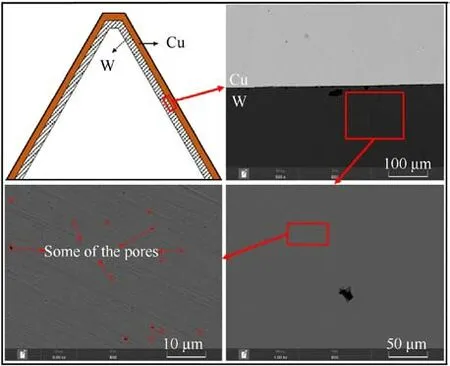
Fig.6.SEM image of the copper-tungsten border in a double-layer liner.
The principle of the pulsed X-ray test and the layout of the penetration test are shown in Fig.8.The shaped charge was placed on a PVC pipe that had a length equal to three times the charge diameter.The PVC pipe was placed on top of the steel plate.Two speed papers were placed along the jet trajectory to measure the average velocity of the jet tip.The pulsed X-ray emitter,the shaped charge, and a film box were placed in the same plane.A certain delay was set for the X-ray emitter trigger to ensure that the entire jet could be projected onto the film.
To evaluate the penetration capability of the double-layer liners,a total of five warheads were used during this study.Two had 1.0-mm single-layer copper liners (Cu#1 and Cu#2), one had a 1.0Cu-0.2W charge liner (#2, the tungsten layer thickness was 0.2 mm), and two had 1.0Cu-0.3W charge liners (#3 and #4, the tungsten layer thicknesses were 0.3 mm).The target plate was made of #45 steel.To reduce the radial boundary effect on the penetration process,the diameter of the target plate was chosen to be 120 mm.
Design a slug-retrieval test was performed.Specifically, a double-layer charge liner (1.0Cu-0.2W, #1) was used in the retrieval test; this was done to verify the jet morphology and to analyze the deformation mechanism of the charge liner under denotation loading.To reduce the difficulty of the recovery test,the recovery device uses#45 steel to pre-consume the high-speed jet,which is not easy to be completely recovered,then water was used to decelerate the subsequent low-speed jet and achieve recovery.This experimental setup is shown in Fig.9.
3.2.Numerical simulations
3.2.1.Material properties
Jet formation is a high-strain-rate process.The Lagrange algorithm often fails for this type of problem due to distortion,whereas the Euler grid is effective.In numerical simulations, the Johnson-Cook (J-C) model is suitable for large-deformation, highstrain-rate, and high-temperature conditions.Therefore, the J-C model and the shock equation of state(EOS)were used to describe the copper and tungsten materials used in this study.The model considered the strain rate and temperature effects on the flow stress.The constitutive model, which was established based on experimental data from previous studies [27,28], could accurately describe the plastic-flow behavior of the copper and tungsten under high-temperature and high-strain-rate conditions.The material properties used in these studies were adopted for the current study,and they are listed in Table 2.Specifically, #45 steel, which has a yield strength of 507 MPa,was used for the target plate.The yield stress defined by the J-C model is expressed as

An 8701 explosive was used,and the Jones-Wilkins-Lee(JWL)EOS was used to describe the detonation and energy release process.The density of the 8701 explosive was 1690 kg/m3and its detonation velocity was 8425 m/s.The Chapman-Jouguet (C-J)pressure was 29.5 GPa, and the pressure, p, could be expressed by Eq.(2).
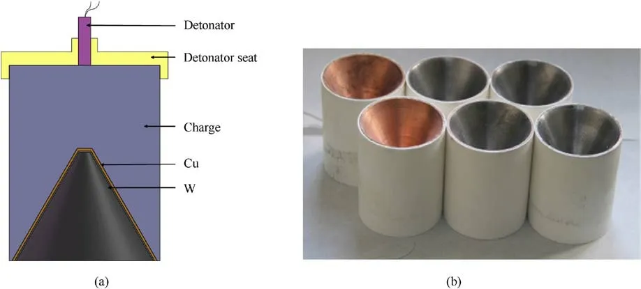
Fig.7.Shaped charges with double-layer liners: (a) structural diagram; (b) physical prototypes.

Fig.8.Pulsed X-ray experimental setup: (a) schematic diagram of the working principle and (b) physical setup.
In Eq.(2), A1, B1, R1, R2, and ω are parameters related to the explosive,and some of these parameter values are listed in Table 3.
3.2.2.Numerical model
Using the Ansys Autodyn-2D software, a two-dimensional symmetric model was established to analyze the jet formation of the double-layer charge liner.This liner had tungsten as the inner layer and copper as the outer layer.According to the charge liner structure depicted in Fig.2,a numerical model for the double-layer liner operating under ideal conditions was developed,and the Euler method was used to simulate the jet formation based on continuum mechanics.The jet profiles at different stages were obtained.The explosive and the charge liner were filled in the Euler domain[30].Moreover,using smaller elements can generally produce more accurate results, yet doing so can also increase the computation time.To make the liner grid better adapt to the thickness of the inner liner, the element size in the Euler domain was set to 0.1 mm × 0.1 mm, and the length of the air domain was set to 450 mm.The boundary of the air Euler domain was set to "Flow-Out".Double-layer charge liner models with different thickness ratios were established for either a constant mass or a constant structure type.For example, the model name "1.0Cu-0.2W" indicates that the outer copper layer has a thickness of 1 mm, the inner tungsten layer has a thickness of 0.2 mm, and the thickness ratio,η, is 0.2.This model is shown in Fig.10.
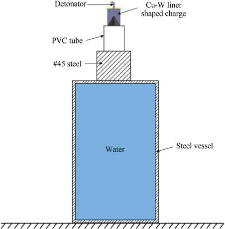
Fig.9.Schematic diagram of the slug retrieval test.

Table 2 Parameters of the shaped charge[27,28].
Simulations were used to study the penetration performance of the double-layer charge liners as the thickness ratio was changed.First, a model was established for the target plate.The distance between the target plate and the shaped charge was equal to three times the charge diameter.To ensure sufficient accuracy and efficiency, the element size in the target plate was set to 0.4 mm × 0.4 mm.The jet formation process was obtained using the Euler solver,and the jet was mapped to the Lagrangian moving elements.The detonation products were removed to reduce the calculation time.The mapped jet contained several pieces of information, such as the initial mass and velocity of the jet, which were imported from the Euler solver[30].The finite element model is shown in Fig.11.
4.Results and discussion
4.1.Pulsed X-ray tests
Fig.12 shows the jets formed by the shaped charges with the double-layer liners.Pictures of the jets were obtained at various times, which were measured from the moment of charge detonation.The jet lengths could be measured from the pulsed X-ray images.The velocity at the jet tip was calculated based on the distance between the two speed-measuring targets and the delay in the triggering time.The results are presented in Table 4.Due to equipment issues, X-ray images were not captured for liner Cu#1.
Fig.12 shows that the morphologies of the jets formed by the T2 copper liner and the double-layer liners were similar.The copper liner jet had good ductility, and the double-layer liner jets did not fracture.The diameters of the jet tips and the effective lengths were obtained from the results of the pulsed X-ray imaging(Table 4).The maximum difference between the jet diameters of the single-layer copper liner and the double-layer charge liners was 13.9%,and the maximum difference between the total lengths of the jets was 16.3%;these differences were due to the differences between the Xray imaging times.
To validate the numerical results obtained during this study,the pulsed X-ray results were compared with the numerical results at the same points in time.An X-ray image of a jet at 39 μs is compared with the corresponding simulated jet in Fig.13, while Table 5 compares the pulsed X-ray and the numerical results for jets at 39 μs and 34 μs.
Fig.13 and Table 5 show that the experimental results for the 1.0Cu-0.2W double-layer charge liner were consistent with the numerical results, indicating that the numerical model had good accuracy.In Fig.13, the red area represents tungsten and the light blue area represents copper.According to the jet formation theory of shaped charges [31], the jet tip formed by the double-layer charge liner was composed primarily of tungsten with high density, which makes the jet have certain advantages in the penetration process.The actual diameter of the jet tip formed by the #3 liner at 39 μs was smaller than the calculated diameter;this result occurred because the numerical simulation was performed under ideal conditions but the actual test could involve a number of uncertainties, such as a charge deviation, machining errors, or deviations in the positions of the detonator seat or the detonation point, which could lead to certain deviations in the experimental results.In general, the morphologies of the jets formed by the double-layer liners were good.The errors in the measured parameters were within 11.07%with respect to the numerical values,which is acceptable.Therefore,it is feasible to use CVD to fabricate double-layer charge liners with tungsten as the inner liner.This method is expected to be widely applicable for the liners of shaped charges.

Table 3 Parameters of the 8701 explosive used in this study [29].

Fig.10.Simulation model of a double-layer charge liner.

Fig.11.Shaped charge penetration model.
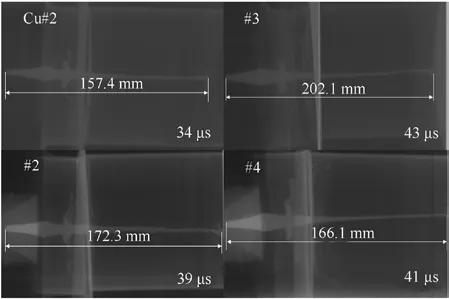
Fig.12.Pulsed X-ray results of the jet formation for double-layer charge liners.
4.2.Jet retrieval
Fig.14 shows the slug obtained from the 1.0Cu-0.2W liner after the jet-retrieval test.The outer surface of the slug was copper and the inner portion was tungsten.The arrow in the left image indicates the jet direction.After detonation,the tungsten in the inner liner that did not contribute to the high-speed jet formation created a slug wrapped by the outer copper.It traveled in the jet direction,and the tungsten content in the slug gradually decreased from the jet tip to the tail.From a macroscopic perspective, the morphological characteristics of the slug were consistent with the simulation results,which further verified the reliability of the numerical model.
Samples of the slug in area A,indicated in Fig.14,were obtained using wire cutting,and the sample microstructures were observed with an SEM.Fig.15 presents an SEM image of a slug sample at the tungsten-copper border, which shows that many cracks were densely distributed throughout the area.The angle between the cracks and the jet direction was obtuse, and the cracks were filled with tungsten.Because the tungsten had a higher density than the copper, the tungsten in the slug moved slower and was overtaken by the copper; this caused cracks in the copper, and the tungsten was pushed into the cracks.This also explains why there was a large amount of tungsten in the back half of the slug.The tungsten content decreased continuously along the jet direction until it was fully covered by copper.
4.3.Penetration results
Table 6 presents experimental and numerical penetration results for the jets formed by the double-layer liners and the singlelayer copper liner.Complete penetration occurred in the target plate during the test with the #4 liner, and the actual penetrationdepth was larger than for the other liners.Fig.16 shows pictures of the liners penetrating the target plates.The figure shows that the penetration performance was affected by the jet formed by the liners.

Table 4 Parameters of the jets formed by the double-layer charge liners.

Fig.13.Comparison of the numerical and experimental results for the 1.0Cu-0.2W double-layer liner.

Table 5 Comparison of the numerical and X-ray-test jet parameter results for the double-layer charge liners.
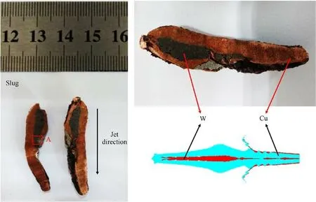
Fig.14.Comparison between the actual retrieved slug and a slug obtained from a numerical simulation.
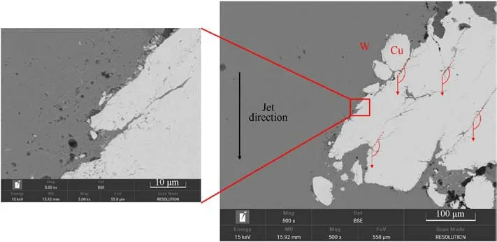
Fig.15.SEM image of area A from the slug in Fig.14.
Table 6 shows that the perforation diameters caused by the double-layer liners were smaller than that produced by the singlelayer copper liner.The actual perforation diameters for the singlelayer copper liner and the double-layer liners deviated from the numerical results by 2.02% and 28.9%-43.7%, respectively.Asindicated by the pulsed X-ray test results,the diameter of the jet tip from the single-layer copper liner was slightly larger than those from the double-layer charge liners.This result primarily occurred because the density of the jet tip from the single-layer copper liner was low; therefore, when the jet contacted the target plate, the large stress caused the particles in the jet tip to expand radially to form a mushroom shape, resulting in a large jet tip diameter.The radially-expanded jet particles overcame the resistance of the target plate,thereby further increasing the perforation diameter.In contrast, the jet tips formed by the double-layer liners had high densities and better penetration capabilities.Fewer particles expanded radially, so the perforations were smaller.Additionally,the X-ray images showed that the jet tips appeared to diverge;this was caused by processing errors and uneven charge liner inner surfaces.This divergence caused the experimental perforation diameter results to be quite different from the numerical results.

Table 6 Penetration results for the shaped jets with respect to the target plates.
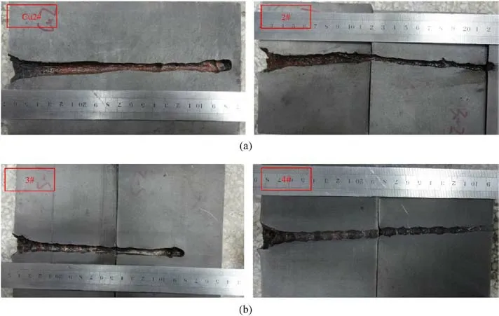
Fig.16.Penetration results for the single-layer and double-layer charge liners.
Table 6 and Fig.16 show that the experimental penetration depth value for the single-layer copper liner deviated from the numerical result,and that the penetration depth of the 1.0Cu-0.2W liner deviated by 7.41% from the numerical value.Moreover, the penetration depths of the 1.0Cu-0.2W and 1.0Cu-0.3W doublelayer charge liners were 11.4% and >10.8% greater than that of the single-layer copper liner.As the thickness of the tungsten layer increased, the tungsten content in the effective jet gradually increased, which significantly contributed to the penetration performance.Therefore,the experimental results showed that the type of double-layer charge liner proposed in this paper could form a jet with a good morphology and an excellent penetration capability;thus,it has potential for application in the armor-penetration field.
4.4.Numerical simulation study
4.4.1.Jet formation and penetration performance of charge liners with equal masses but different thickness ratios
For typical armor,the front section,which has a velocity greater than 3 km/s,is the effective portion of the jet,while the rear section does not contribute much to the penetration.Therefore,3 km/s was taken as the critical penetration velocity, and the section with a velocity between 3 km/s and the jet tip velocity,Vj,was taken as the effective jet length (Fig.17) [8,32].
The jet morphologies of the double-layer shaped liners with different thickness ratios before hitting the target and under ideal conditions are shown in Fig.18.The figure indicates that the jets were quite different for different thickness ratios.As the thickness ratio increased, an increasing amount of tungsten was converted into the jet, resulting in an increasing effective jet length.Finally,the jet flow was completely composed of tungsten,while the outer copper liner only contributed to the slug formation.However, it is not necessarily true that more tungsten in the jet is always better.However, it is not that the more tungsten content in the jet is, the more favorable it is.The tungsten jet with poor ductility will break,which will seriously affect the penetration ability of the jet.Numerical simulations of the penetration process were performed for η values of 1.25,0.66,0.375,and 0.2 when the mass of the doublelayer charge liner was held constant.
Fig.19 and Table 7 present the simulation results.The results indicate that, as η increased, neither the velocity at the jet tip, Vj,nor the effective jet length, L, changed significantly (≤3%).According to the effective charge theory, when the total mass of the charge liner and the contact area of the effective charge remain constant, the jet-crushing velocity is also constant.Moreover, the penetration depth did not increase consistently with increases in the thickness ratio;rather,it first increased and then decreased.The maximum penetration depth, PM, which was achieved when η =0.375,was 23.6%higher than the penetration depth when η =0.2.When η =0.66,the penetration depth was 22.3%higher than when η = 0.2.As the thickness ratio increased further, the penetration depth decreased significantly,and when η =1.25,the penetration depth was 10% lower than when η = 0.66.Hence, there was an optimal thickness ratio, ηb, that produced the best double-layer charge liner penetration performance.In this study,ηb= 0.375.
To explore the reason why the penetration depth first increased and then decreased, the first 60 μs of the penetration process was analyzed for η= 0.2, 0.375, 0.66, and 1.25, as shown in Fig.20.As shown by the jet morphologies presented in Fig.18,when η=0.2,the effective jet was composed of both tungsten and copper but copper accounted for the majority of the jet.When the tungsten at the front of the jet was depleted,the penetration was continued by the copper; therefore, the penetration depth was small.When η increased to 0.375 and 0.66, the effective jet was primarily composed of tungsten,while a small amount of copper was present in the back section of the effective jet.Because of its good ductility,the copper contributed to the jet continuity by reducing the occurrence of jet fracture as the penetration process progressed,thereby significantly improving the jet penetration capability.When η increased to 1.25,the effective jet was composed solely of tungsten,while copper formed the slug.Due to the poor ductility of tungsten, jet fracture occurred during the penetration process,which significantly reduced the jet penetration capability.Nonetheless, the final penetration depth for this case was 10.1% higher than when η = 0.2.

Fig.17.Effective jet length, L, and velocity at the jet tip, Vj.

Fig.18.Jet morphologies for double-layer charge liners with equal masses and different thickness ratios: (a) η = 1.25; (b)η = 0.66; (c)η = 0.375; (d)η = 0.2.

Fig.19.Influence of the thickness ratio on the jet formation and the penetration performance.
4.4.2.Jet formation and penetration performance of charge liners with the same structure type and different thickness ratios
The thickness of the copper layer of the double-layer charge liners with the same structure type but different thickness ratios remain unchanged at 1 mm and the thickness of the tungsten layer is designed on this basis.Therefore, in ideal conditions, the morphologies and formation parameters of the jets of double-layer charge liners with the same structure type but different thickness ratios are presented in Fig.21 and Table 8.
Table 8 shows that both the velocity at the jet tip and the effective jet length were greater for η=0 (i.e., a purely copper liner)than for the other four thickness ratios.Fig.21 shows that,as the thickness ratio increased,the double-layer liner mass increased continuously,while both the velocity at the jet tip and the effectivejet length decreased significantly.With an increase in the liner mass, the jet velocity must decrease when the charge remains constant;this is why Vjand L had smaller values than for the singlelayer copper liner.When η = 0.2, Vjwas 13.2% lower than when η = 0, and the effective jet length decreased by 25.6%.As η increased from 0.2 to 1, tungsten gradually replaced copper as the primary component in the effective jet.However,as η continued to increase,there were decreases in Vjand L.Moreover,a large amount of tungsten was converted into the back section of the effective jet and the slug,thereby causing decreases in the velocities of the back section and slug and a reduction in the penetration capability.When η = 1, Vjwas 32.2% lower than when η = 0, while the effective jet length decreased by 54.8%.Based on the jet morphologies in Fig.21, numerical simulations of the penetration process were conducted when η = 0, 0.2, 0.3, 0.5, and 1.

Table 7 Jet and penetration results for double-layer charge liners with equal masses and different thickness ratios.

Fig.20.The first 60 μs of the penetration process for jets formed by double-layer charge liners with equal masses and different thickness ratios: (a) η= 1.25; (b) η=0.66; (c) η= 0.375; (d) η= 0.2.

Fig.21.Jet morphologies of double-layer charge liners with the same structure type and different thickness ratios: (a) η = 0; (b) η = 0.2; (c) η = 0.3; (d) η = 0.5; (e) η = 1.

Table 8 Jet and penetration results for double-layer charge liners with the same structure type and different thickness ratios.
Table 8 shows that as η increased,the penetration performance of the double-layer charge liner first increased and then decreased,and that the perforation diameter was greatest when η=0.Fig.22 shows the penetration results for the double-layer charge liners with same structure type and different thicknesses ratios.The penetration depth was 5.1%higher when η=0.2 than when η=0;this result occurred because the composition of the effective jet tip changed from copper to tungsten, and thus the tip had a higher density.Fig.21 indicates that, although the inner tungsten layer was converted into a jet, due to the small thickness of the inner liner and thus the small tungsten content, the tungsten jet was short and was exhausted quickly during the penetration process.As the thickness ratio increased, the penetration performance improved significantly because the liner mass increased and more tungsten was converted into the jet.When η=0.3,the penetration depth was 27.1% greater than when η = 0.Although Vjfor η = 0.3 was similar to that for η = 0.2,due to the increase in the tungsten layer thickness,more tungsten was converted into the effective jet,which resulted in a better penetration capability.However, the penetration capability did not improve when η increased from 0.3 to 1; rather, it declined to a certain extent because of decreases in the effective jet length and velocity,as well as jet fracture caused by poor ductility.Therefore,for the double-layer charge liners with the same structure type and different thickness ratios, the optimal thickness ratio,ηb= 0.3.To improve the double-layer charge liner penetration performance, the thickness ratio, the effective length,and the velocity at the jet tip should all be considered.
In conclusion, whether the double-layer charge liners under consideration have equal masses and different thickness ratios or the same structure type and different thickness ratios, to achieve the best penetration performance,the velocity at the jet tip and the effective jet length should be accounted for so that the formed jet can achieve an optimal morphology and velocity.
5.Conclusions
This paper proposes the method of using CVD to fabricate a double-layer charge liner with tungsten as the inner liner.Doublelayer charge liner prototypes were prepared using CVD,and the jet formation and penetration performance were evaluated using pulsed X-rays, static penetration tests, and a jet-retrieval analysis.This study produced four primary conclusions:
(1) CVD was used to fabricate double-layer charge liners,termed 1.0Cu-0.2W and 1.0Cu-0.3W, with two different thicknesses.An SEM was used to observe the microstructure of the tungsten layer,and it was found that this layer contained many pores with an average diameter of 0.834 μm; these pores affected the density of the tungsten layer.However,under detonation conditions, the effects of the pores on the jet formation were negligible.

Fig.22.Penetration results for double-layer charge liners with the same structure type and different thickness ratios: (a) η = 0; (b) η = 0.2; (c) η = 0.3; (d) η = 0.5; (e) η = 1.
(2) Pulsed X-ray images and static penetration tests showed that the double-layer charge liners prepared by CVD were able to form effective jets.The errors between the X-ray test results and the numerical results were within 11.07%.The experimental penetration depth results for the single-layer copper liner and the double-layer liners deviated by 13.89% and 7.41%.The penetration depths of the two types,1.0Cu-0.2W and 1.0Cu-0.3W double-layer charge liners increased by 11.4% and >10.8%, respectively, from that of the single-layer copper liner and the test results, which verified the feasibility of using the CVD method to fabricate double-layer charge liners with a high-density and high-strength refractory metal as the inner liner.
(3) The macroscopic morphology of a retrieved slug was similar to that obtained from a numerical simulation.SEM images showed that, at the tungsten-copper border, the slug had many cracks.The direction of the cracks with respect to the jet direction formed an obtuse angle.These cracks were caused by the difference in the velocities of the two materials.This result explains the deformation mechanism of the tungsten-copper double-layer charge liners under detonation loading.
(4) Numerical simulations were performed for the jet formation and penetration processes for double-layer charge liners with equal masses and different thickness ratios and on those with the same structure type and different thickness ratios.The results showed that when the thickness ratio, η,was greater than 0.2,the double-layer charge liner formed a tungsten-copper jet, which played an important role in the penetration process.When η ≥ 1, the jet was entirely composed of tungsten.Because the jet was affected by the poor ductility of the tungsten, jet fracture occurred, which had an adverse effect on the penetration performance.The optimal thickness ratios of the two structures of double-layer charge liners were determined to be 0.375 and 0.3,respectively.
Declaration of competing interest
The authors declare that they have no known competing financial interests or personal relationships that could have appeared to influence the work reported in this paper.
Acknowledgements
The work presented in this paper was funded by the China Postdoctoral Science Foundation(Grant No.2022M721614)and the opening project of State Key Laboratory of Explosion Science and Technology,Beijing Institute of Technology(Grant No.KFJJ23-07M).
- Defence Technology的其它文章
- Explosion resistance performance of reinforced concrete box girder coated with polyurea: Model test and numerical simulation
- An improved initial rotor position estimation method using highfrequency pulsating voltage injection for PMSM
- Target acquisition performance in the presence of JPEG image compression
- Study of relationship between motion of mechanisms in gas operated weapon and its shock absorber
- Data-driven modeling on anisotropic mechanical behavior of brain tissue with internal pressure
- The effect of reactive plasticizer on viscoelastic and mechanical properties of solid rocket propellants based on different types of HTPB resin

