Research on the flow stability and noise reduction characteristics of quasi-periodic elastic support skin
Lu Chen, Shao-gang Liu, Dan Zhao, Li-qiang Dong, Kai Li, Shuai Tang, Jin Cui, Hong Guo
Department of Mechanical and Electrical Engineering, Harbin Engineering University, Harbin,150001, China
Keywords:Flow stability Quasi-period Flexible wall Elastic support element Hydrodynamic noise
AB S T R A C T To enhance flow stability and reduce hydrodynamic noise caused by fluctuating pressure, a quasiperiodic elastic support skin composed of flexible walls and elastic support elements is proposed for fluid noise reduction.The arrangement of the elastic support element is determined by the equivalent periodic distance and quasi-periodic coefficient.In this paper, a dynamic model of skin in a fluid environment is established.The influence of equivalent periodic distance and quasi-periodic coefficient on flow stability is investigated.The results suggest that arranging the elastic support elements in accordance with the quasi-periodic law can effectively enhance flow stability.Meanwhile, the hydrodynamic noise calculation results demonstrate that the skin exhibits excellent noise reduction performance, with reductions of 10 dB in the streamwise direction,11 dB in the spanwise direction,and 10 dB in the normal direction.The results also demonstrate that the stability analysis method can serve as a diagnostic tool for flow fields and guide the design of noise reduction structures.
1.Introduction
During submarine operations,noise is inevitably generated.This noise can be categorized into mechanical, propulsion, and hydrodynamic sources.As the submarine’s speed increases, the proportion of hydrodynamic noise rapidly escalates and becomes the primary source of underwater sound [1,2].Therefore, controlling the hydrodynamic noise of submarines is crucial for enhancing their acoustic stealth and ensuring operational effectiveness.
Laying a flexible skin on the surface of a submarine can effectively mitigate fluid disturbance by consuming turbulent kinetic energy during deformation, thereby delaying layer flow transition and reducing resistance and hydrodynamic noise [3-6].From analyzing the surface flow stability of flexible skin, scholars have conducted extensive research on the structural form and operational mechanism of flexible skin.The concept of drag reduction through the use of flexible skin was first proposed by Kramer[7,8],who observed that dolphins could swim at unusually high speeds,indicating their ability to delay transition to turbulence.Garrad[9]investigated the impact of flexible wall parameters and continuous elastic support on flow stability through qualitative equations,demonstrating that appropriate stiffness in both the flexible wall and continuous elastic support can effectively suppress disturbance shock waves within a flow field.Yeo [10,11] has also studied flow stability over viscoelastic layers.He found that the flow over compliant walls with suitable properties may indeed be stabilized.These research results demonstrate that the small disturbance on the skin surface conforms to the linear flow stability theory,which lays a theoretical foundation for establishing the flow stability equation of skin.Boiko and Kulik et al.[12,13]performed boundary layer stability calculations for flexible coatings with practical properties for the first time, realizing the use of two flexible coatings to control the turbulent boundary layer.
Subsequently, Riley [14] proposed a uniform periodic elastic support skin, which is composed of discrete elastic support elements arranged periodically on the surface and bottom of the skin.The growth rate of disturbance wave on the skin surface was measured.The results show that compared with continuous flexible wall skin, uniform periodic elastic support skin can significantly improve the suppression ability of fluid disturbance.Tang[15] proposed a skin structure made of micro floating raft arrays which consists of a compliant wall supported on micro floating raft arrays.Compared with the rigid wall and single viscoelastic wall,the skin with appropriate parameters shows a strong stabilizing effect of TSW on the boundary-layer flow.Then,a skin composed of a porous compliant wall and micro floating raft elements is proposed by Cui [16].The skin can reduce the arising of TSI and CIFI modes in boundary-layer flow, leading to a favorable performance for delaying boundary-layer transition.
However, compared with the quasi-periodic structure, the disturbance wave is more likely to propagate and diffuse in the whole structure [17], which also leads to the limitations of the uniform periodic elastic support skin in maintaining the flow stability.Therefore, this paper proposes a quasi-periodic elastic support skin structure,which is composed of a flexible wall and elastic support elements.The quasi-periodic arrangement of elastic support elements is determined by using the equivalent periodic distance and quasi-periodic coefficient.The concept of the quasiperiodic structure comes from the phononic crystal, which has potential engineering applications in vibration isolation control,noise suppression, and the design of new sensors [18-20].Quasiperiod is a state between period and disorder, which has the characteristics of the short-range disorder and long-range order.The existence of disorder makes the elastic wave appear localization phenomenon when it propagates[21-23].Compared with the periodic structure, the quasi-periodic structure can suppress the larger disturbance caused by the diffusion of elastic waves, which also provides a way for us to control the disturbance waves in the flow by using the disorder of quasi-periodic structure.
In this paper, the quasi-periodic support skin is taken as the research object, and the characteristic equation of flow stability is calculated to analyze the effect of the structural parameters of the quasi-periodic elastic support skin on the flow stability.Through the above research,it was proved that the structure had the ability to maintain the flow stability, and the reasonable structural parameters of the skin are obtained.The noise reduction characteristics of the skin are obtained based on the boundary element theory, whose purpose is to obtain the noise reduction characteristics of the skin through the observation of the sound field.The amount of noise reduction shows the noise reduction performance of the quasi-periodic structure proposed.
2.Characteristic equation of flow stability of quasi-periodic elastic skin
2.1.Dynamic equations of quasi-periodic elastic supporting skin
As shown in Fig.1, the physical model of quasi-periodic elastic support skin is composed of the flexible wall and elastic support elements.The elastic support elements are alternately arranged under the flexible wall with spacing L1=l and L2=ql,respectively.Where,l is the base quasi-periodic distance,q is the quasi-periodic coefficient, which indicates the quasi-periodic degree, L is the equivalent periodic distance, which is the fixed periodic distance formed by any three adjacent elastic support elements.
For this physical model, the flexible wall of skin is taken as the research object,and its dynamic equation is established as follows:
where,D,T and mcare the flexural rigidity,surface tensor and mass of the flexible wall, respectively.η(x,t) is the longitudinal displacement of the flexible wall under the fluid disturbance,Ffand Fnare the hydrodynamic force and the force of the elastic support unit, respectively.
In order to determine the position of the force acting on the elastic support unit,the position of the isolator in the X direction by using Dirac functions δ1(x) and δ2(x) can be expressed as follows:
Substituting Eqs.(2) and (3) into Eq.(1), the dynamic equation can be obtained as follows:

Fig.1.Physical model of quasi-periodic elastic support skin.
Because there are three undetermined parameters L1,L2and l in the basic form of skin dynamic equation, the equation can not be solved directly at this time.To solve the problem of the equation,two kinds of periodic intervals L1and L2of skin and quasi-periodic interval l of the foundation are expressed by equivalent periodic distance L and quasi-periodic coefficient q.
The Dirac function can be expressed as:

To facilitate the subsequent analysis and mathematical transformation of the dynamic equation, the force Fnof the elastic support element and the hydrodynamic force Ffare respectively expressed as:
Zsand Zfin Eqs.(8) and (9) respectively represent the impedance function of elastic support unit and fluid impedance function.On this basis, it is assumed that the longitudinal displacement of skin under the action of fluid disturbance is a simple harmonic response.η(x,t) can be expressed as:
By substituting Eqs.(8)-(10)into the dynamic Eq.(7)of the skin equivalent model, the dynamic equation can be obtained as follows:
Taking the mass of the elastic support element as the research object, the force balance equation is obtained as follows:
where,kT,kμ and mdare the spring stiffness,damping,and mass of the elastic support element, respectively.
Substituting Eq.(10)into Eq.(12),the force balance equation can be obtained as follows:

2.2.Characteristic equations of flow stability
Firstly, the amplitude function ^η(x) in the skin equivalent dynamic equation can be obtained by Fourier transform:
Then,the partial derivative term of the amplitude function ^η(x)of the flexible wall in the equivalent dynamic equation of the skin can be obtained by Fourier transform:
According to Poisson’s summation formula and Fourier transform, the infinite summation term in the equivalent dynamic equation of skin is treated as follows:
By substituting Eqs.(15)-(19) into the dynamic Eq.(11) of the skin equivalent model, the equivalent dynamic equation can be obtained as follows:
where, η(α) is the Fourier transform of the amplitude function of the flexible wall, η(μn) is the Fourier transform of the vibration displacement response of the elastic support element.
In order to simplify the equation form, the coefficient term function before η(α) in Eq.(20) can be expressed as:
Zfis a function of the wavenumber, α, and the frequency, ω.In order to derive Zf, we note that for the Fourier mode of wavenumber and frequency,the perturbed flow function of the potential flow field is of the form:
where, A is a complex constant.Then, applying dynamic and kinematic boundary conditions at the fluid-solid interface can be expressed as:
In this case, substituting Eq.(23) into Eq.(22), the original equation becomes:
In order to facilitate the subsequent analysis and solution, Eq.(24) is mathematically treated, that is, the vibration amplitude Fourier transform η(α) of the skin flexible wall in the original formula is replaced by η(μm)(η(α)≡η(μm)),the flow stability equation becomes:
Since the equation solves the vibration displacement response η(μn) of the elastic support element, rather than the vibration amplitude η(μm) (η(α)) of the skin flexible wall, in order to eliminate the independent variables in the equation, Eq.(23) can be transformed into:

In Eq.(26),the independent variable η(μm)is separated from the equation by Kroneckerfunction δmn, and it can be seen from the equation that if n≠m is the solution vector η(μn)≡0 of the equation under the action of Kronecker function δmn,it indicates that there is no inelastic support element.
First of all,from Eq.(24),it can be seen that η(μn)is the solution vector and other variables are the coefficient matrix,and since the equation has infinite solutions, the coefficient matrix of Eq.(26)should meet the following requirements:
Since the determinant expressed in Eq.(27)contains Kronecker function δmn,it is difficult to directly solve it.Therefore,Eq.(25)can be transformed into:
Compared with Eqs.(25) and (28) eliminates the independent variable η(μm),while compared with Eq.(26),it does not introduce Kronecker function δmn,which makes it relatively easy to solve the equation.According to the conditions satisfied when the equation has infinite solutions,Eq.(28) can be transformed into:
3.Calculation model of hydrodynamic noise
In this paper, the bi-directional fluid-structure interaction (FSI)method is used to calculate the pulsating pressure in the flow field on the skin surface,and then the FW-H equation for hydrodynamic noise calculation is established, and the obtained pulsating pressure is substituted into the equation as the sound source input item of the equation to obtain hydrodynamic noise.
3.1.Governing fluid-structure equations
3.1.1.Governing equations for the fluid
In this computational simulation, the large eddy simulation model is used to solve problem.A filter function is established to divide the transient variables of the fluid into large-scale components and small-scale components.After filtering the Navier-Stokes equation,the following equation is obtained:
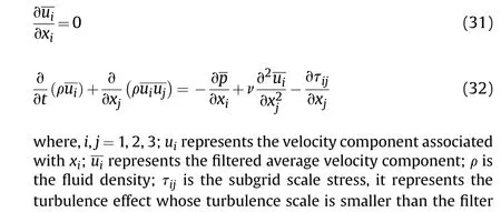

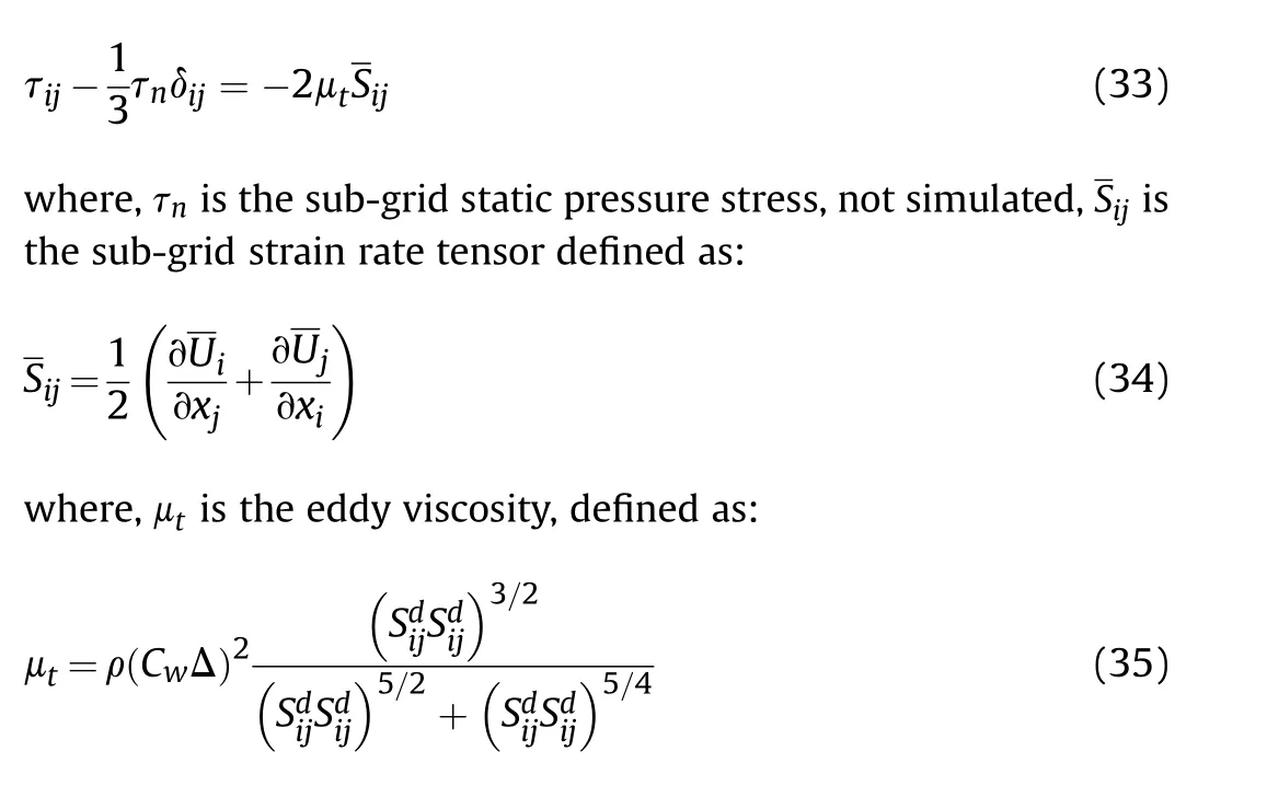
where,Cwis the empirical coefficient of WALE model,and Sdijis the subgrid deviatoric strain tensor.The WALE model solution process takes into account the influence of the viscosity near the wall,and has strong adaptability in the transition from laminar flow to turbulent flow, making the model results more accurate.Substituting Eq.(35) into Eq.(32) can complete the closing work of the N-S equation, and the pulsating pressure distribution on the skin surface can be solved by large eddy simulation theory,thus laying the foundation for the calculation of hydrodynamic noise.
3.1.2.Governing equations for the structure
In the process of structural calculation in this paper, an elastic flat plate of composite material with a flexible surface covering layer is considered.Assuming that it satisfies the basic assumptions of elastic mechanics and the material is linear elastic,the governing equations for the structure can be written as:
where, usi(i = 1, 2, 3) represents the structural displacement component;σij(i,j=1,2,3)represents the nine components of the stress tensor;ρsrepresents the density of the structural unit body;ci(i = 1, 2, 3) are the damping coefficients in the three directions respectively.Considering isotropy, these three coefficients are equal.In this paper, the influence of material damping on drag reduction is not considered, and they are uniformly taken as 0.In addition,the calculation of this paper does not consider the effect of body force.
For the geometric equation,still based on the small deformation assumption of elastic mechanics,the linear geometric equation can be written as:
where,εij(i,j = 1, 2, 3) is the 9 components of the strain tensor.
The physical equation is no different from the ordinary elastic mechanics problem, as follows:
where, E is the elastic modulus of the material; G is the shear modulus; μsis the Poisson’s ratio of the material.The above Eqs.(36)-(38) together constitute the governing equations for the quasi-periodic elastic support skin in the bi-directional fluidstructure interaction.In the calculations in this paper, the initial conditions of the structural part start with zero displacement(usi=0), zero velocity (vsi= 0), and zero stress(σij= 0).
3.1.3.Governing equations for the fluid-structure interface
At the interface of fluid-solid coupling, the equality or conservation of fluid force and solid stress, displacement, velocity and other variables should be satisfied.Here, a unit on the fluid-solid interaction surface is still considered, and fi(i = 1, 2, 3) represents the force of the fluid in three directions on the solid, and ufi(i=1,2,3),vfi(i=1,2,3)represent the displacement and velocity components of the flow field grid on the fluid-solid interface surface.Let(l,m,n)represent the normal vector of the fluid-structure interaction surface at a certain point.The following kinematic coupling boundary conditions and dynamic coupling boundary conditions are satisfied on the fluid-solid coupling boundary.
Dynamically coupled boundary conditions are as follows:

The no-slip moving boundary condition is also satisfied on the fluid-solid coupling boundary, that is, on the fluid-solid coupling boundary,the tangential velocity of the flow field is the same as the tangential velocity of the structure, which happens to be included in the second group of equations in Eq.(40).
In this paper, the calculation order of the flow field first is adopted in the coupling calculation,that is,the flow field governing equation is solved first to obtain the flow field force,and then this result is substituted into the dynamic coupling boundary condition.After the solution is completed, the structural displacement is obtained, and then the result is substituted into the kinematically coupled boundary condition and the flow field grid is updated.After the update is completed,the flow field governing equation is solved, and so on until convergence.
3.2.FW-H equation
In 1969, based on the Curle equation, Williams and Hawkings[24]applied generalized functions to obtain a more commonly used acoustic formula,that is,the FW-H equation,which can be written as:
where, p′is the far-field sound pressure, p′= p- p0; δ(f) is a Dirichlet function; unis the velocity component of the incoming flow velocity in the xidirection.
The three items on the right end correspond to the radiation noise caused by quadrupole, dipole and monopole as the sound source.The Acoustic module of Fluent software is based on FW-H The equation is established, and the sound source, sound field environment and sound propagation are simulated by the FW-H equation, and the distribution of each pole unit is calculated by the method of time domain integration.
4.Results and discussion
4.1.Flow stability analysis of quasi-periodic elastic supported skin
4.1.1.Effect of equivalent periodic distance on flow stability
Firstly,the effect of different equivalent periodic distance on the flow stability is studied when the elastic supports are arranged periodically,i.e.q=1.The flexural stiffness coefficient D =0.15,the flexible wall tensor coefficient T = 0.1, the spring stiffness coefficient kcT= 0.1, the mass coefficient mcd= 0.6, and the damping coefficient kcμ =0.2 of the elastic support element of the flexible wall.According to the parameter selection range of Mead and Pujara (1971), the flow stability on the skin surface of the quasiperiodic elastic support with equivalent periodic distance L of 1,2,4,9,12 and 16 are selected for comparative analysis,to select the best equivalent cycle interval to maintain the flow stability.
As shown in Fig.2,the characteristic curve of α-ωrobtained by taking the equivalent periodic distance L as 1,2,4,9,12,16 is shown,and the type of flow state can be known through image analysis.It can be seen from Fig.2 that when the equivalent periodic distance L is 1 and 2, the fluid is in a flow unstable state, and because the characteristic curve is about ωr=0.In this case,the flow instability is caused by disturbance co excitation.When the equivalent periodic distance L is 4, the fluid is in the flow instability state, and because the characteristic curve is surrounded by three closed loops, the flow instability is caused by mode combination.When the equivalent periodic distance L is 9,the characteristic curve does not form the flow instability region,and the flow state of the fluid includes neutral stability and flow stability When the equivalent periodic distance L is 12,the fluid is in the flow instability state,and because the characteristic curve is surrounded by six groups of symmetrical closed-loop, the flow instability is caused by the disturbance coexcitation and mode combination.When the equivalent periodic distance L is 16, the fluid is in the flow instability state, and the flow instability region formed by the characteristic curve is expanding outward, and the flow is unstable.The instability has spread to the whole flow field.In conclusion, the flow stability improves gradually with the increase of the equivalent periodic distance L,but when the equivalent periodic distance L is too large,the rigidity of the skin structure is insufficient,which is not conducive to the maintenance of the flow stability.When the equivalent periodic distance is equal to 9,although there is no flow instability, it will change into flow instability under the action of disturbance because of the neutral stability.In order to obtain the reasonable value of the equivalent periodic distance,it is necessary to further judge in combination with the skin’s suppression of the fluid disturbance.
As shown in Fig.3,the α-ωicharacteristic curve of equivalent periodic distance L is taken as 1,2,4,9,12,and 16 respectively.The height of the image in the vertical axis indicates the frequency of fluid disturbance,and the width in the horizontal axis indicates the intensity of fluid disturbance.It can be seen from Fig.3 that when the equivalent periodic distance L is 1, 2 and 4 respectively, the frequency of fluid disturbance increases first and then decreases according to the characteristic curve, while the intensity of fluid disturbance decreases gradually.When the equivalent periodic distance L is 9, the characteristic curve presents obvious periodic distribution along the vertical axis, and it can be seen from the width and height of its distribution along the horizontal and vertical axis by taking one of the periodic images, at this time,the generated flow Compared with the former, the frequency and intensity of volume disturbance are the lowest.When the equivalent periodic distance L is 12 and 16,the frequency and intensity of fluid disturbance are improved from the characteristic curve, and the fluid disturbance has tended to develop in an uncontrollable direction.To sum up, when the equivalent periodic distance L = 9,the skin has a good effect on the suppression of fluid disturbance,so the reasonable value of the equivalent periodic distance L is 9.
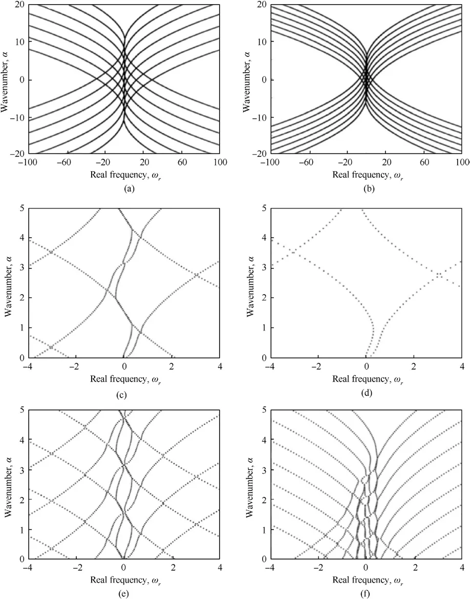
Fig.2.α-ωr characteristic curve with different values of the equivalent periodic distance: (a) L = 1; (b) L = 2; (c) L = 4; (d) L = 9; (e) L = 12; (f) L = 16.
4.1.2.Effect of quasi-periodic coefficient on flow stability
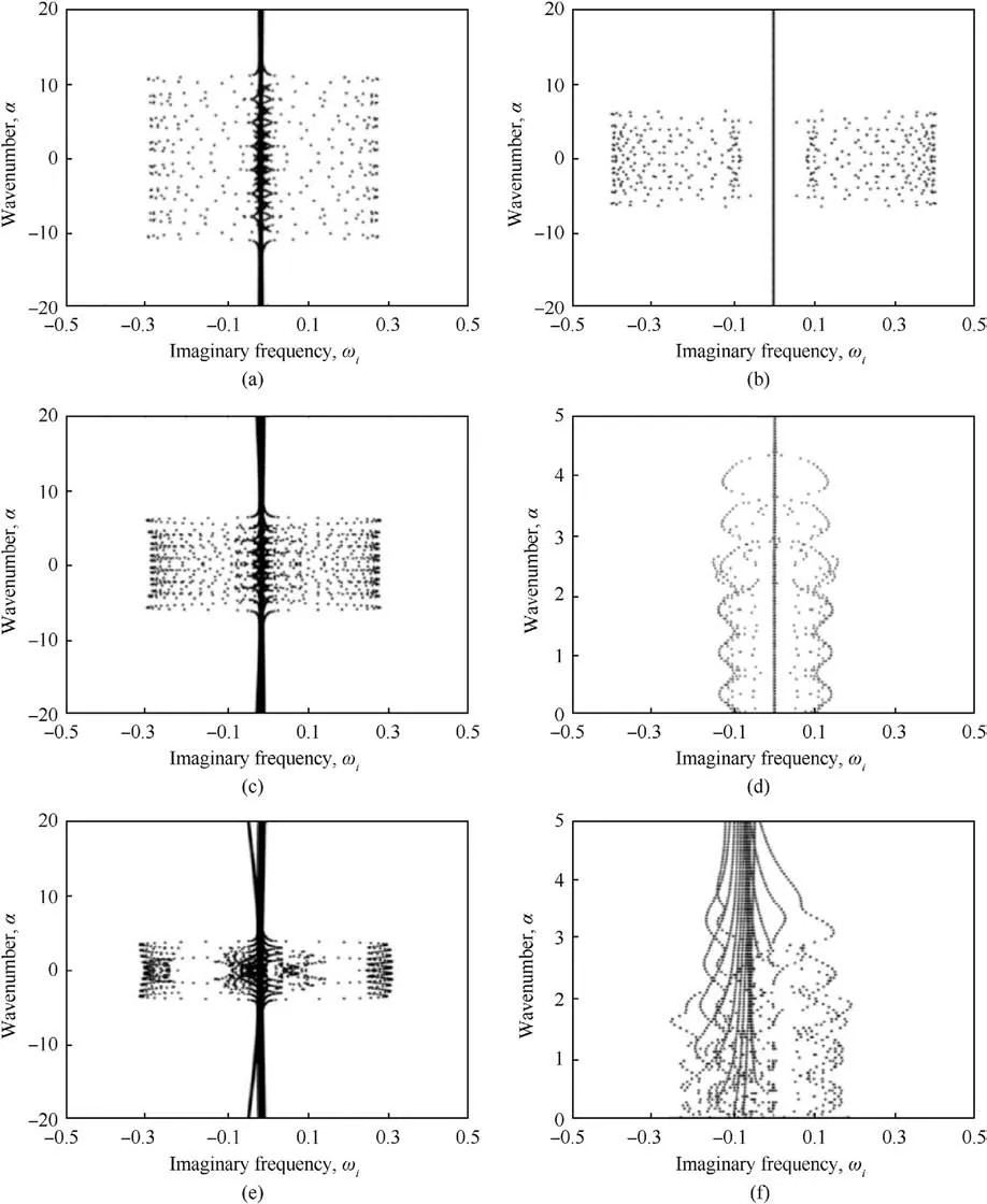
Fig.3.α-ωi characteristic curve with different values of the equivalent periodic distance: (a) L = 1; (b) L = 2; (c) L = 4; (d) L = 9; (e) L = 12; (f) L = 16.
According to Figs.2 and 3, when the equivalent periodic distance L=9 is used, the flow state does not show flow instability and has a good restraining effect on the fluid disturbance.At this time, the fluid on the skin surface has good flow stability, so the equivalent periodic distance L is determined to be 9.Under the condition of equivalent periodic distance L=9 and constant parameters of the flexible wall and elastic support material,the quasiperiodic coefficients q of 1,2,3,4,5 and 6 are selected respectively for comparative analysis of the flow stability of the skin surface of quasi-periodic elastic support, to select the quasi-periodic coefficient with the best effect of maintaining the flow stability.
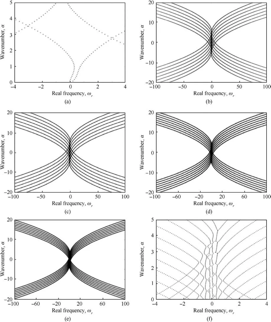
Fig.4.α-ωr characteristic curve of quasi-periodic coefficient q with different values: (a) q = 1; (b) q = 2; (c) q = 3; (d) q = 4; (e) q = 5; (f) q = 6.
As shown in Fig.4,when the quasi-periodic coefficient q is taken as 1,2,3,4,5,and 6,respectively,α-ωrcharacteristic curves can be obtained.The type of flow state can be obtained by comparing the images.It can be seen from Fig.4 that when the quasi-periodic coefficient q is taken as 1, the fluid presents two states of neutral stability and flow stability.When the quasi-periodic coefficient q is taken as 2,3,4,5 and 6,the fluid presents a state of flow instability,and because the characteristic curve is symmetric about ωr=0,the flow instability is induced by disturbance co excitation.It can be seen from the image that the flow state under the condition of uniform periodic structure includes neutral stability, which indicates that if the skin does not sufficiently restrain the disturbance of the fluid, the neutral stability will change to flow instability under the disturbance.At this time, the flow stability of the fluid will become worse or even develop into complete turbulence.Although the flow state under the condition of quasi-periodic structure appears flow instability, the flow state under the condition of the quasi-periodic structure may not be stable Whether the flow instability will completely destroy the flow stability and lead to the transition of laminar flow to turbulence depends on the suppression of fluid disturbance by the skin.To sum up, it is impossible to directly determine the reasonable quasi-periodic structure parameter q from the perspective of the flow state.To obtain the reasonable value of the parameter, it is necessary to further determine it in combination with the skin’s suppression of fluid disturbance.
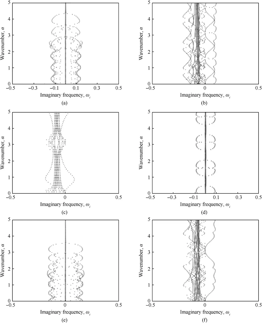
Fig.5.α-ωi characteristic curve of quasi-periodic coefficient q with different values: (a) q = 1; (b) q = 2; (c) q = 3; (d) q = 4; (e) q = 5; (f) q = 6.
As shown in Fig.5, the α-ωicharacteristic curve of quasiperiodic coefficient q at 1, 2, 3, 4, 5, and 6 respectively, the height of the vertical axis represents the frequency of fluid disturbance,and the width of the horizontal axis represents the intensity of fluid disturbance.It can be seen from Fig.5 that when the quasi-periodic coefficient q is 1,2,3 and 4 respectively,the frequency and intensity of fluid disturbance first increase and then decrease, and when q=4,the skin has the best suppression effect on fluid disturbance.When the quasi-periodic coefficient q are 5 and 6 respectively,the frequency and intensity of fluid disturbance increase, and when q = 6, the fluid disturbance has included various frequencies The flow stability of rate components has been completely destroyed.It can be seen from the images that choosing the appropriate quasiperiodic coefficient q can effectively suppress the fluid disturbance.Comparing the characteristic curves of the homogeneous periodic structure and the quasi-periodic structure, it can be seen that the frequency of fluid disturbance generated by q=1 and q=4 are basically similar, while the intensity of fluid disturbance is significantly reduced when q = 4.In conclusion, under the condition that the quasi-periodic coefficient q is reasonable, the quasiperiodic skin has a better restraining effect on the fluid disturbance than the uniform periodic skin,to maintain the flow stability and avoid the laminar transition into turbulence.
Combined with Figs.4 and 5, when the quasi-periodic coefficient q = 4, although the flow state is unstable, the transition of laminar flow turbulence can be avoided by restraining the fluid disturbance.At this time, the skin has good flow stability, so the quasi-periodic coefficient q is determined to be 9.

Fig.6.Flow chart of bidirectional fluid-structure coupling.

Table 1 The parameters of the skin material.

Fig.7.Meshing results of fluid domain.
4.2.Research on noise reduction characteristics of quasi-periodic elastic support skin
4.2.1.Parameter setting of simulation model
The flow noise generated by the skin surface in this paper was simulated using the commercial software ANSYS Workbench 17.0 for bidirectional fluid-structure coupling.The Fluent module was used for flow field calculation,and the Transient Structural module was used for structure calculation.The data between the two were analyzed by System Coupling for bidirectional fluid-structure interaction.At the same time, the Acoustics module in Fluent was opened to calculate flow noise.The numerical simulation system to establish the overall calculation in Workbench is shown in Fig.6.
Then, the hydrodynamic noise at the characteristic points of X/Y/Z three directions can be calculated by FW-H equation.According to the results,the variation law of the hydrodynamic noise without skin and with skin can be obtained.According to the stability analysis in the previous section,if the equivalent periodic distance of skin is L=9 and the quasi-periodic coefficient is q=4,the actual spacing of skin elastic support elements is L1=3.6 mm and L2=14.4 mm.The parameters of the skin material are shown in Table 1.The skin is laid on a rigid plate surface,the fluid domain model size is 740 × 150 × 150 mm, and the skin structure size is 380mm × 150 mm at the bottom of the flow field,180 mm away from the input end of the flow field.The fluid medium selected in this paper is water.The kinematic viscosity is γ=1.13902 mm2/s2and Reynolds number is Re = 6.5846 × 10⁶.
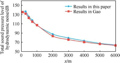
Fig.8.Total sound pressure level of hydrodynamic noise in the X direction.
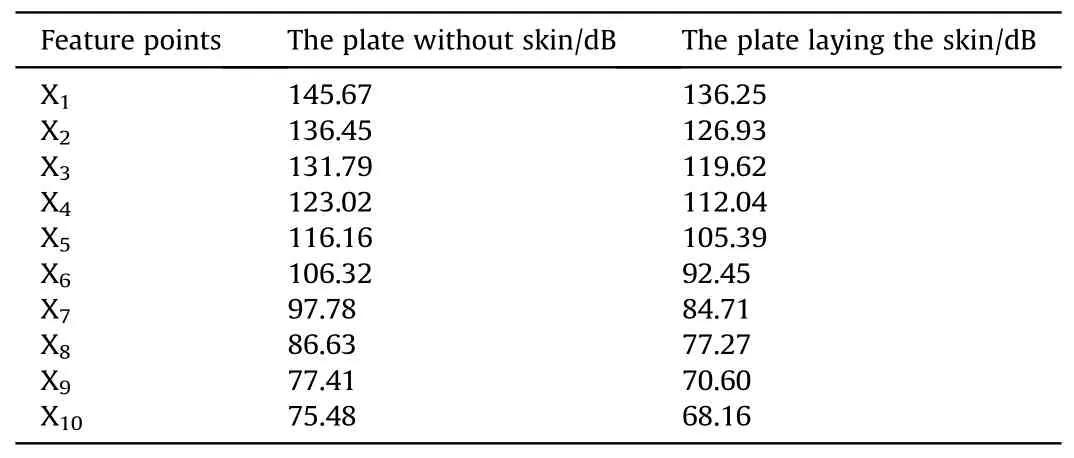
Table 3 Total sound pressure level of hydrodynamic noise in X direction.
Set the inlet velocity as 7.5 m/s,and the outlet pressure is 0.The bottom surface is free slip boundary condition to prevent the flow velocity from being affected by wall shear stress.Both side and top surfaces are symmetric boundary conditions to ensure that the flow state is not affected in the spreading direction.
The pre-processing software ANSYS ICEM CFD is used to divide the flow field grid.In order to obtain the flow field information of boundary layer transition,boundary layer grid should be divided on the fluid-solid contact surface, and the first layer grid should be encrypted.In order to ensure that the fluid domain and solid domain grid nodes can correspond,the contact surface grid should also be refined.The meshing results are shown in Fig.7.
At this time, the number of meshes in the skin fluid domain is about 250,000,and the overall mass of the meshes is maintained at 0.7, which can ensure the solution accuracy and calculation convergence.Moreover, the wall function value is within a reasonable range of 30-60, which can identify the vortices of different scales in the flow field.
4.2.2.Noise reduction characteristics of skin
(1) The variation law of hydrodynamic noise along the X direction.
Select 10 calculation feature points with uniform spacing along the X direction, and the coordinate values are shown in Table 2.
In order to verify the accuracy of numerical calculation results,we calculate the hydrodynamic noise in the X-direction of the multi-layer covering structure in Gao’s [25] paper using the calculation method in this paper and compare it,as shown in Fig.8.The multilayer covering structure in Gao’s paper is composed ofmultiple layers of flexible materials, and the surface presents flexibility.The comparison results show that the calculation results of this paper and Gao are basically consistent, which verifies the feasibility of the numerical method used in this paper.

Table 4 Coordinates of characteristic points calculated in the Y direction.
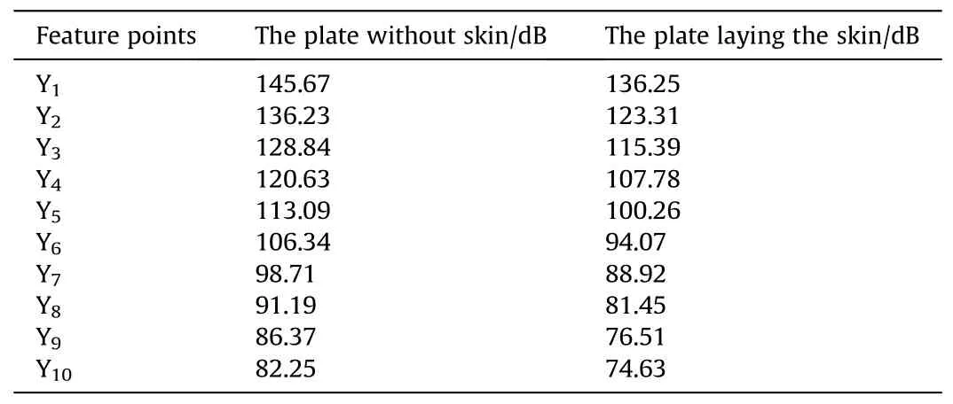
Table 5 Total sound pressure level of hydrodynamic noise in Y-direction.
Use FW-H equation to solve the hydrodynamic noise at each calculation feature point, and get the total sound pressure level of the hydrodynamic noise along the X direction under the condition of not laying skin and laying skin, as shown in Table 3.
According to the data analysis in Table 3,under the condition of laying skin, the hydrodynamic noise decreases about 10 dB, and along the X direction, with the increase of distance, the hydrodynamic noise decreases gradually, and the farther away from the sound source, the greater the noise reduction.
According to the analysis of the X-direction sound field vector cloud chart shown in Fig.9, the hydrodynamic noise along the streamwise direction is significantly reduced under the condition of skin laying, which indicates that the skin can effectively consume turbulent kinetic energy to maintain the flow stability.
(2) The variation law of hydrodynamic noise along the Y direction.
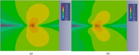
Fig.9.Vector cloud chart of X-direction sound field: (a) Plate without skin; (b) Plate laying the skin.
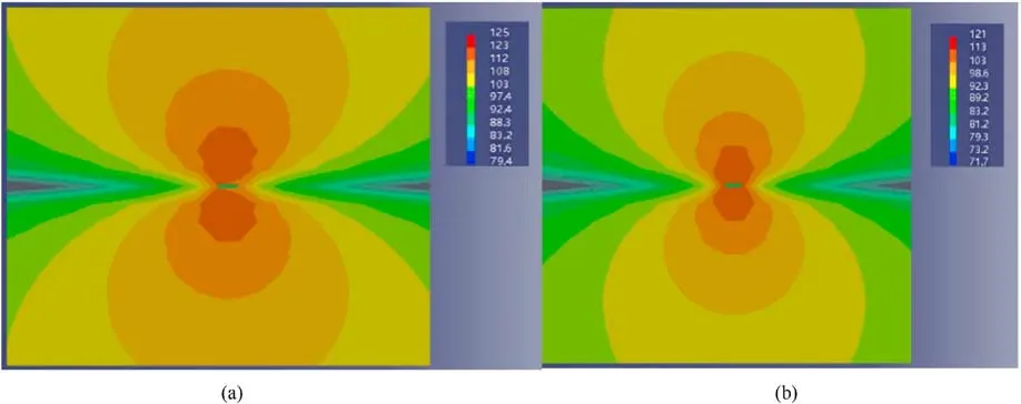
Fig.10.Vector cloud chart of Y-direction sound field: (a) The plate without the skin; (b) The plate laying the skin.

Table 6 Coordinates of characteristic points calculated in the Z direction.
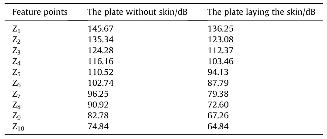
Table 7 Total sound pressure level of hydrodynamic noise in the Z direction.
Select 10 calculation feature points with uniform spacing along the Y direction, and the coordinate values are shown in Table 4.

Fig.12.Curve of pulsatile pressure with time.
Use FW-H equation to solve the hydrodynamic noise at each calculation feature point, and get the total sound pressure level of hydrodynamic noise along Y direction under the condition of no skin and no skin,as shown in Table 5.
According to the analysis of the data in Table 5, under the condition of laying the skin,the hydrodynamic noise has a decrease of about 11 dB, and the closer to the sound source along the Y direction,the greater the hydrodynamic noise is,otherwise,the smaller the hydrodynamic noise is, and the greater the attenuation amplitude of the hydrodynamic noise near the sound source is under the same distance change.
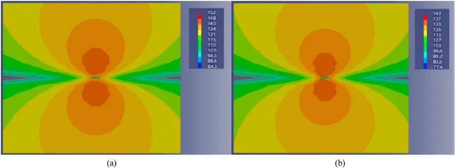
Fig.11.Vector cloud diagram of Z-direction sound field: (a) Plate without the skin; (b) Plate laying the skin.
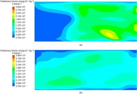
Fig.13.Cloud map of turbulence intensity: (a)Rigid plate plate; (b)Plate laying the skin.
According to the analysis of the Y-direction sound field vector cloud chart shown in Fig.10, the hydrodynamic noise along the spanwise direction is significantly reduced under the condition of laying the skin,which indicates that the skin can effectively weaken the pulsating pressure to achieve the purpose of restraining the fluid disturbance.
(3) The variation law of hydrodynamic noise along Z direction.
Select 10 calculation feature points with uniform spacing along the Z direction, and the coordinate values are shown in Table 6.
To solve the hydrodynamic noise at each calculation feature point, and get the total sound pressure level of the hydrodynamic noise along the Z direction under the condition of not laying skin and laying skin respectively, as shown in Table 7.
According to the data analysis in Table 7,under the condition of skin laying,the hydrodynamic noise has a decrease of about 10 dB.Besides, the magnitude of the hydrodynamic noise along the Z direction is negatively related to the sound source distance, and the hydrodynamic noise along the Z direction is more affected by the distance change.
According to the analysis of the Z-direction sound field vector cloud chart shown in Fig.11,under the condition of skin laying,the hydrodynamic noise along the normal direction is significantly reduced, indicating that the skin can effectively reduce the radiation sound pressure and thus reduce the detection range of the hydrophone.
Fig.12 shows the fluctuation of the pressure in the turbulent near-wall region at 4 observation points.It can be found that the dynamic pressure of the turbulent boundary layer presents a kind of randomness and fluctuation in the time domain, and the fluctuation is around a fixed value.After the skin is laid, the pressure pulsations in the near-wall area are small and uniform, and the maximum pulsations can reach 2.5 Mpa.
Fig.13 shows the turbulence intensity of the flow field with and without skin.By comparing Fig.13(a)and 13(b),it can be found that without skin, the turbulent kinetic energy can reach up to 2400 J/kg,and the turbulent energy distribution is very uneven,indicating that the turbulent mixing effect is very violent, which will cause strong fluctuations in the boundary layer pressure.In the case of skin, the turbulent field is relatively stable, and the turbulent kinetic energy is generally lower than 1500 J/kg.This shows that the skin structure can effectively suppress the turbulent pulsation and reduce the pulsation excitation of the submarine shell.
In conclusion, the total sound pressure level of hydrodynamic noise at each calculation feature point along the X/Y/Z direction is obtained, and the relevant data are imported into the acoustic software to obtain the sound field distribution cloud chart.Through the analysis of the chart,the decibel number of the skin to weaken the streamwise,spanwise and normal hydrodynamic noise and the variation law of the hydrodynamic noise along each direction are obtained.
5.Conclusions
In order to suppress fluid disturbance and reduce hydrodynamic noise, a quasi-periodic elastic support skin structure composed of the flexible wall and the elastic support element is proposed in this paper,and its flow stability and noise reduction characteristics are investigated.The main conclusions are as follows:
(1) In this paper, a quasi-periodic elastic supported skin structure is proposed,which is modeled by the direct equilibrium method.The dynamic effect of the fluid environment on the skin is considered in the modeling process.The characteristic equation of the skin flow stability is obtained by Fourier transform.According to the property of infinite solution of the skin flow stability characteristic equation,the equivalent form of skin flow stability characteristic equation is derived.
(2) The flow stability characteristic equation of the skin with quasi-periodic elastic support is solved,and the flow stability of the skin with different equivalent periodic distance and the quasi-periodic coefficient is compared and analyzed.The results validate that the elastic support element arranged in quasi-periodic law can maintain the flow stability better than that arranged in periodic law,and the skin can maintain the flow stability better when the equivalent periodic distance L = 9 and quasi-periodic coefficient q = 4.
(3) The hydrodynamic noise at each calculation feature point is simulated, and the noise reduction characteristics of quasiperiodic elastic support skin are obtained.The results reveal that the quasi-periodic elastic support skin has a good noise reduction effect, which can reduce the hydrodynamic noise on the streamwise, spanwise and normal direction by about 10 dB,11 dB and 10 dB respectively,which shows that the quasi-periodic elastic support skin can effectively improve the acoustic recessiveness of submarine.
To sum up,the structure parameters of the quasi-periodic elastic support skin can maintain the flow stability.At this time, the skin can effectively suppress the fluctuating pressure and reduce the hydrodynamic noise.The research results provide a theoretical reference for improving the acoustic recessiveness of submarines.
Declaration of competing interest
The authors declare that they have no known competing financial interests or personal relationships that could have appeared to influence the work reported in this paper.
Acknowledgements
The authors would like to acknowledge National Natural Science Foundation of China (Grant Nos.52075111, 51775123) and Fundamental Research Funds for the Central Universities (Grant No.3072022JC0701).
- Defence Technology的其它文章
- Evolution of molecular structure of TATB under shock loading from transient Raman spectroscopic technique
- MTTSNet:Military time-sensitive targets stealth network via real-time mask generation
- Vulnerability assessment of UAV engine to laser based on improved shotline method
- Free-walking: Pedestrian inertial navigation based on dual footmounted IMU
- Investigation of hydroxyl-terminated polybutadiene propellant breaking characteristics and mechanism impacted by submerged cavitation water jet
- Estimation of surface geometry on combustion characteristics of AP/HTPB propellant under rapid depressurization

