Dissipation and amplification management in an electrical model of microtubules: Hybrid behavior network
Sedric Ndoungalah, Guy Roger Deffo, Arnaud Djine, and Serge Bruno Yamgou′e
1Department of Physics,Faculty of Science,University of Bamenda,P.O.Box 39 Bamenda,Cameroon
2Research Unit of Automation and Applied Computers(UR-AIA),Department of Electrical Engineering,IUT-FV of Bandjoun,University of Dschang,BP 134,Bandjoun,Cameroon
3Department of Physics,Higher Teacher Training College Bambili,The University of Bamenda,P.O.Box 39 Bamenda,Cameroon
Keywords: microtubule,dissipation and amplification,hybrid behavior,solitary wave solutions
1.Introduction
Due to its great importance in various biological processes, protein dynamics has been widely studied in recent years.[1,2]Microtubules (MTs) are a typical example of such structures.They represent the main components of the cytoskeleton and play a crucial role in electrical activities within eukaryotic cells,including, for example, cellular division, intracellular information processing, regulation of synaptic inputs, modulation of neural firing, regulation of developmental plasticity, and mediation during transport of electrical signals.[3]
MTs are hollow cylinders formed by protofilaments aligned in directions parallel to their axis.The approximate values of their outer and inner radii are 25 nm and 15 nm,respectively.[4–6]Their lengths are of the order of micrometers or millimeters.Many theoretical and experimental studies have been envisaged to analyze their properties and dynamics.For instance, Prielet al.studied experimentally the electrodynamic properties of MTs.[7]The obtained results demonstrated that MTs are excellent conductors of electrical signals.They can also amplify an electric current stimulated by an applied voltage pulse.Through electroorientation experiments, Minoura and Muto found that the conductivity of the MT was 1500 mS/m, which was 15 times higher than that of the surrounding buffer.[8]Freedmanet al.investigated ionic currents through microtubule nanopores.[9]The obtained results showed that the nanopores have asymmetric inner and outer conductances.Havelkaet al.investigated multi-mode electro-mechanical vibrations of an MT.[10]They showed that electrically polar collective vibration modes of MTs lead to a quasi-periodic electric oscillating potential.Based on the kink solitons and breathers,Zdravkovicet al.explained the nonlinear dynamics of MTs.[11,12]
To better understand the dynamics of MTs and to elucidate their role in the electrical activities of cells, several electrical models of these biological systems have been proposed in the literature.In fact, since the pioneering work by Tuszynskiet al.on nonlinear electrical transmission lines (NLTLs) modeling ionic wave propagation along actin filaments,[13]growing interest has been devoted to the use of NLTLs to mimic the behavior of MTs.For instance, the ionic-conduction properties of an MT have been investigated through a model of NLTL.[14]Ilicet al.used the same model to show that the localized ionic wave could be used to explain the behavior of MTs as biomolecular transistors capable of amplifying electrical information in neurons.[15]This model was also exploited to describe the electrostatic potential coupled to the propagating localized waves along MTs.[16]Similar studies have also been conducted by Freedmanet al.and Sataricet al.considering a two-dimensional electrical model[9]and an NLTL with negative resistive components,[17]respectively.Based on another model, these authors and other coworkers investigated the polyelectrolyte character of MTs.[18]A new NLTL model has also been introduced to investigate the creation and propagation of localized pulses of positive ions flowing along cellular MTs.[19]Recently,Ndjomatchouaet al.demonstrated that the electrical wave propagation in an MT could be modeled by a discrete NLTL including a cubic negative nonlinear resistance.[20]More recently,using an electrical model with strongly nonlinear resistive elements, Ghomsiet al.studied the capability of the inner part of an MT.[21]Other models of NLTLs mimicking the dynamics of MTs have also been realized.[22,23]
Analyzing the above cited works, we note that existing models to mimic the electrical behavior of MTs in the bandpass domain have only focused on the dissipative character of these systems.However, experimental evidence suggests that MTs act as biological electrical wires that can amplify electrical signals via the flow of condensed ion clouds.For instance,Prielet al.have shown that taxol-stabilized MTs behave as biomolecular transistors capable of amplifying electrical information.[7]In addition,this author and other coworkers obtained similar results by studying the effect of calcium on electrical energy transfer by MTs.[24]Hence,these works suggest that a complete description of the dynamics of the electrical bio-signals’ propagation along MTs via a model of an NLTL can be made by taking into account both dissipation and amplification characteristics of MTs.To the best of our knowledge,such a study has not yet been considered.
In this paper, we aim to broaden the understanding of models of MTs as nonlinear electrical transmission lines with nonlinear resistive elements.Specifically,we undertake simultaneously herein the investigation of the amplification and the dissipation of electrical signals in an electrical model of MTs which is presented along with its exact dynamical equation in the next section.In Section 3,we first show that the dynamics of modulated waves in the network is governed by the standard nonlinear Schr¨odinger equation extended by a dissipation/amplification term.Next,the signs of various coefficients of this equation are studied.Finally, the baseband modulational instability of the amplitude equation is investigated.In Section 4, we investigate the exact and approximate solitary wave solutions of the governing equation.Analytical investigations of these obtained solutions are performed in Section 5.We conclude our paper in Section 6.
2.Model description and dynamic equation
2.1.Model presentation
The physical electrical model of a microtubule considered in the current paper is depicted in Fig.1.It was described in some detail in Ref.[20]and consists of several identical blocks connected in sequence one to the other.Each block includes a shunt nonlinear conductance–capacitance (J(Vn)–C(Vn)) circuit and a series resistance–inductance(R–L)circuit.The first nonlinear element is a varicap diode whose differential capacitanceC(Vb+Vn)= dQn/dVnis a nonlinear function of the voltageVn.For low voltages around the dc bias voltageVb,Qn(Vn)at the(n)th node can be defined by[25,26]
whereC0is the characteristic capacitance.αandβare positive real parameters.The second nonlinear element is negative nonlinear resistance satisfying the following expansion:[27]
In this relation,Bis an amplitude factor determined by the slope atV=0 V.d1andd2are voltages which determine the zeros ofJ.For the active behavior ofJ,d1andd2have the opposite signs,while they are positive for the passive behavior ofJ.[27,28]

Fig.1.Schematic representation of the electrical analogy of the MT model.
ConsideringB2=B(d1+d2) andB1=-Bd1d2, relation(2)can be rewritten as
Here,B2andB1represent the quadratic nonlinear and linear coefficients,respectively.The physical dimensions ofB1,B2andBare [?-1], [?-1·V-1] and [?-1·V-2], respectively.Note that ford1=-d2, we obtain the expression of the negative nonlinear resistance effects of ionic flow through nanopores used in Refs.[20,21].
Applying Kirchhoff laws to the circuit of Fig.1, the following differential equations governing the dynamics of signal voltage(Vn(t))in the network are obtained:
withu20=1/(LC0),β1=RB,α1=RB2,λ=RB1/4,γ1=(RC0-LB1),γ2=-(RC0α+LB2),γ3=(LB+RC0β) andn=1,2,...,N.Nrepresents the total number of blocks.In this study,numerical investigations are made for the following values of the network parameters:[16,27]
2.2.Linear dispersion law
The linear dispersion law of the model of Fig.1 is derived and examined in this subsection.To this end,we consider the solution of Eq.(3)asVn=V0exp(i(kn-ωt))withV0,kandωrepresenting the small wave amplitude, the wave number,and the angular frequency, respectively.Putting this solution into Eq.(3),and neglecting the terms of power greater thanV0we obtain the angular frequency and group velocity associated with the wave packet as
Equation (5) shows that our system is a band-pass filter.Nevertheless,we note that its allowed frequency band considerably depends on the sign of parameterλwhich represents the nonlinear conductance’s contribution to the angular frequency.Indeed,two cases can be distinguished.
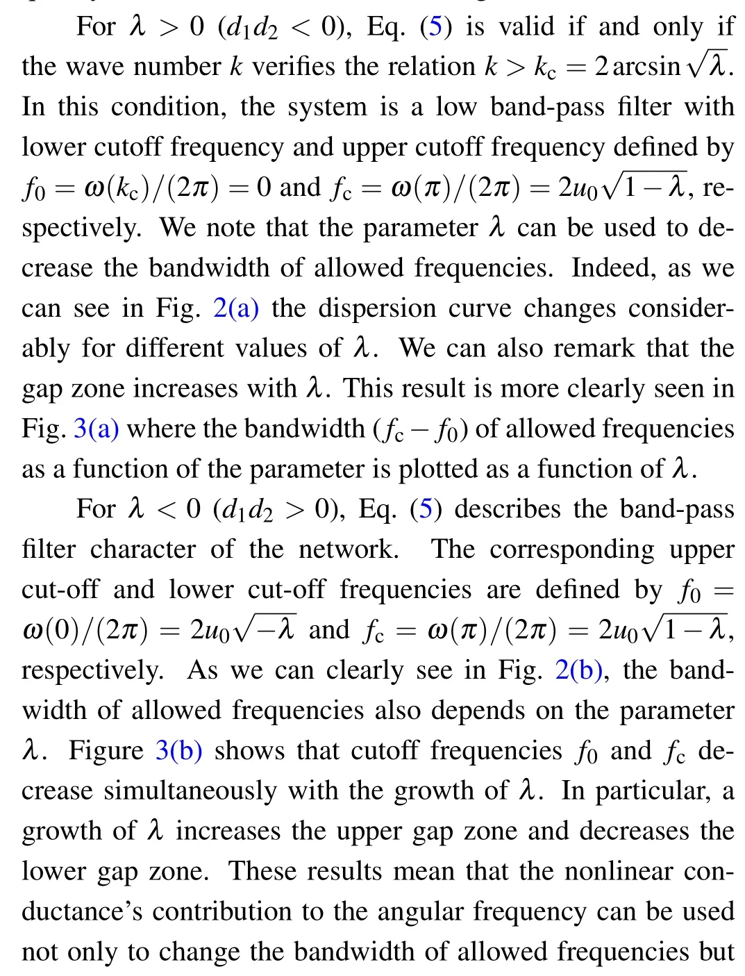

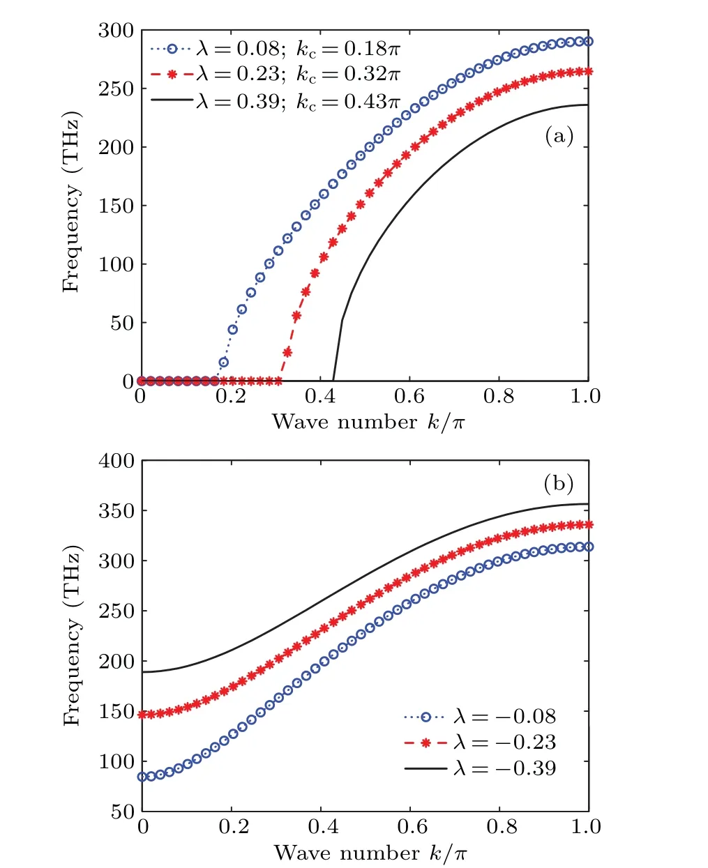
Fig.2.Effect of the parameter λ on the linear dispersion curve of the network showing evolution of the frequency f = ω/(2π) as a function of the wave number k (rad/cell) with network parameters (4): (a)d2=-d1 (λ >0);(b)d2=d1 (λ <0).
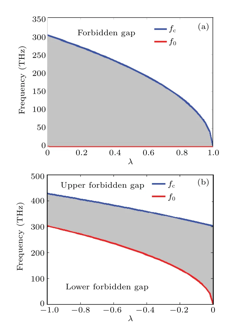
Fig.3.Variation of the bandwidth of allowed frequencies as a function of the parameter λ with the network parameters(4): (a)d2=-d1(λ >0);(b)d2=d1 (λ <0).
3.Extended nonlinear Schro¨dinger equation and baseband modulational instability
3.1.Extended nonlinear Schr¨odinger equation
This section is devoted to the derivation of the nonlinear equation describing the motion of nonlinear modulated waves in the MT electrical model of Fig.1.Thus, we consider the reductive perturbation approach in the semidiscrete approximation.In this method, the carrier is treated with its discrete character and the envelope is described in the continuum approximation.Let us consider the voltage signal solution of Eq.(3)to be of the form[28]
whereθ=kn-ωtis the phase and cc stands for the complex conjugate of the preceding expression.εis a small parameter.Solution(6)includes the fast local oscillation through the dependence of the phaseθ,and then preserves the discrete character of the network, while the dependence of the envelope part described byA(x,τ) on the slow variablesτ=ε2tandx=ε(n-μt) takes care of the slow variation in amplitude.We then order the damping coefficient in Eq.(3) so that the damping and nonlinearity effects appear in the same perturbation equations.In particular, we assume that the dissipation effect of the network is weak.Thus, we consider thatγ1is a perturbed parameter of orderε2.Inserting Eq.(6)into Eq.(3),we obtain different equations as power series ofε.
First,the terms proportional toεexp(iθ)andε2exp(iθ)give us,respectively,the angular frequency and group velocity obtained and investigated in the previous section.
Next, from the terms of order [ε2exp(0iθ)] and[ε2exp(2iθ)],we obtain,respectively,the continuous componentsA20(x,τ)and the second harmonicA22(x,τ)defined by
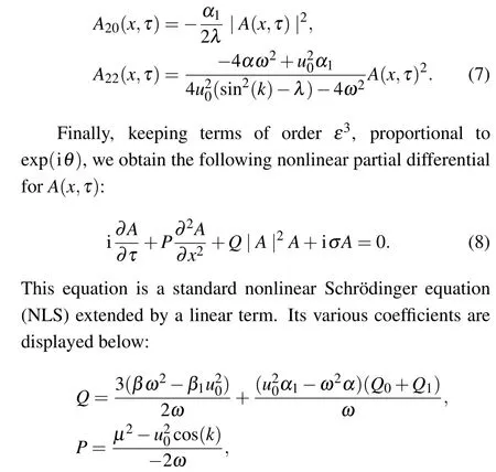
Equation (8) includes the dissipation/amplification effect beside the linear group velocity dispersion (GVD) and the self phase modulation (SPM) represented, respectively,by the parametersPandQ.For instance,σis the dissipation/amplification coefficient.It is due to the nonlinear and linear resistances respectively,in shunt and series branches of the network.From its expression, it is clearly observed that this coefficient is an explicit function of the nonlinear resistance parameters (B,d1andd2) and can take any value and any sign depending on the considered values of these parameters and also of the magnitude of the resistanceR.Hence,it becomes important to study its sign.
Specifically,sinceu20>0,the nature(amplification or dissipation coefficient) ofσonly depends on the sign of coefficientγ1,which is an explicit function of the network’s parameters.By definition,the coefficientsL,C0,R,andBare positive.Therefore,the sign and the nature of coefficientσonly depend on the sign of the parametersd1andd2.Various combinations of these parameters have been used in the literature.[27]
Ford1d2<0,let
1.Ford1d2>0, we haveσ>0: in this case,σis a dissipation coefficient.
2.Ford1d2<0 andR>Rcr,we haveσ>0: in this case,σis also a dissipation coefficient.
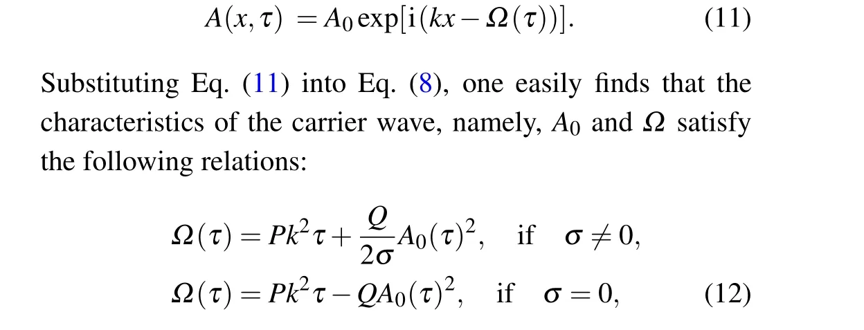
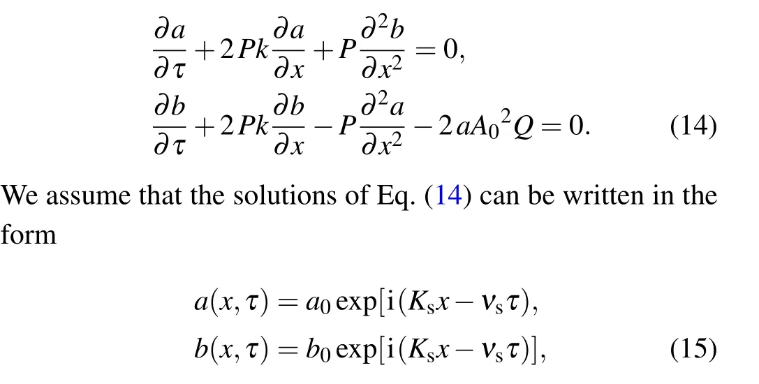
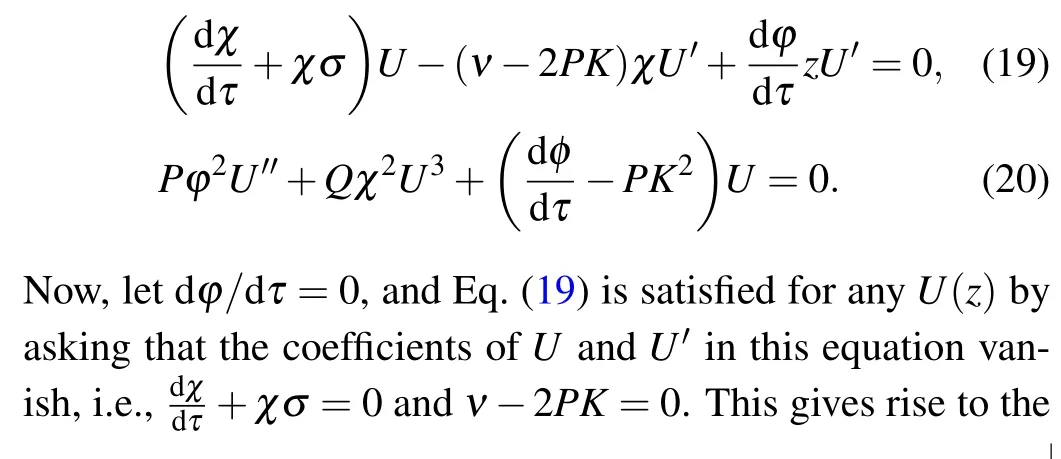
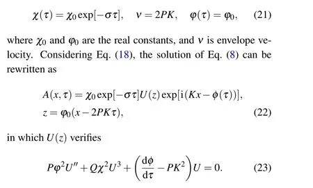
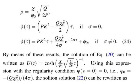
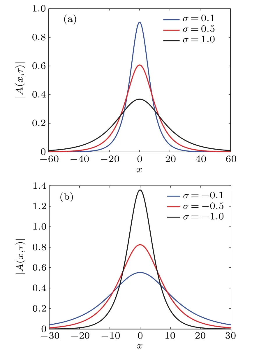
3.Ford1d2<0 andR 4.Ford1d2<0 andR=Rcr,we haveσ=0: in this case,the amplitude equation(8)leads to the well-known nonlinear Schr¨odinger equation.This result is in perfect agreement with existing results on the dissipative NLTL in which the dissipative terms of the NLS equation disappear when the dissipation elements (resistances) are not considered.[30–32]However, in contrast to these previous results, the dissipation is not neglected in the model studied in this paper.In other words,the resistance(R)always exists in our system but its effect is counterbalanced by the effect of the nonlinear conductanceJ.This new result shows clearly that the nonlinear resistance can be exploited to control the dissipation in the network of Fig.1. Although Eq.(8)has been derived in the context of NLTL mimicking the behavior of MTs,the well-known versatility of NLS type equations makes it legitimate to expect that its applications can extend beyond the NLTL.For instance,Okalyet al.derived a similar equation when studying the solitary wavelike solutions in nonlinear dynamics of damped DNA systems.[33]Likewise, it has been used by Gianniniet al., Marquieet al.,and Demiray to analyze the propagation of bright and dark solitons in lossy optical fibers,[34]to study the modulational instability in a real electrical lattice,[35]and to investigate the modulation of nonlinear waves in a thin elastic tube filled with a viscous fluid,[36]respectively. In the particular caseσ=0, the discrete version of the eigenvalue problem of Eq.(8),namely, has also been studied by Wenet al.in order to further understand the discrete rogue waves phenomena in nonlinear optics and relevant fields.[37]In addition, an extended discrete version of Eq.(8)including the quintic nonlinearity has been used in Ref.[38]. Before ending this subsection, we present in Fig.4 the behaviors of the dispersion and nonlinear coefficients (PandQ)for values of the wavenumberkchosen in the first Brillouin zone (0≤k ≤π).These plots show that these coefficients can be positive,null or negative depending on the values ofkand the sign ofλ.These results are useful for understanding the dynamics and the kind of localized waves that can propagate in the electrical model of MTs considered in this work.Indeed, it is well known that the kind of solutions the NLS equation has strongly depends on the sign of the product of these parameters.[30–32] Fig.4.Nonlinear coefficients and linear dispersive curves as a function of the wavenumber k with the network parameters(4)for the same network parameters as Fig.2: (a) λ =4.66×10⁻⁴ (kc =0.043 rad), (b)λ =-4.66×10⁻⁴. In this section,we focus our attention on the investigation of baseband modulational instability of the amplitude equation(8).To this end,we first consider the plane wave solutions characterized by the time-dependent angular frequency?(τ),the wavenumberkand the time-varying unperturbed amplitudeA0=A0(τ)in the form[39,40] withA0(τ)=A00exp[-στ] andA0(τ)=A00forσ/=0 andσ=0,respectively. Now,consider a small real phase perturbation of the amplitude(a(x,τ))and phase(b(x,τ))as follows: Substituting Eq.(13) into the extended NLS Eq.(8), the linearizing terms give the system whereKsandνsrepresent, respectively, the wavenumber and the angular frequency of the perturbation; anda0andb0are complex constant amplitudes.Substitution of Eq.(15) into Eq.(14) leads to a system of two linear algebraic homogeneous equations fora0andb0.After some algebraic manipulations,the dispersion relation gives The plane wave will be unstable against small modulation if the perturbation diverges with time, that is, the right hand side of Eq.(16)is negative.In this condition,the angular frequencyνsof the perturbation is complex and its imaginary part is considered as a measure of the growth rate of the perturbation defined as Equation (17) shows that the baseband modulational instability of the plane wave (11) occurs if and only ifPQ>0 andK2s In the present section, we focus our attention on the derivation of the exact and approximate representations of the solitary wave solutions of Eq.(8) which correspond to localized wave solutions of Eq.(3).We first note that in the particular caseσ=0,Eq.(8)becomes a standard integrable NLS equation and admits both bright and dark as solitary wave solutions.However,forσ/=0,Eq.(8)becomes no longer integrable.Thus,to proceed with the integration of this equation,we introduce the following ansatz: whereνandKare real constants;φ(τ)and?(τ)are the real functions of variableτto be determined;U(z)is a real envelope function.Substituting Eq.(18) into Eq.(8), we expand and factor out the exponential factor.Then, using a prime to denote a differentiation with respect toz,we obtain the following equations from the imaginary and real parts,respectively: Hence, the initial partial differential equation in the complex variableA(x,τ) is now reduced to a single second order ordinary differential equation in the real amplitudeU(z) given by Eq.(23).In the literature,many powerful techniques have been used to solve such an equation, and several types of solutions have been constructed.[41–50]Here,with the aid of the direct method, our attention is focused on the derivation of the solitary wave solutions of this equation.The kind of these solutions strongly depends on the sign of the productPQas discussed below. Fig.5.Effects of the dissipative parameter on the shape of bright soliton(25)at τ =1,k=0.5π and for the same network parameters as in Fig.3(a). Here, we are concerned with the investigation of the bright-like soliton solution of Eq.(8).This type of solution exists whenPQ>0.For this purpose,we introduce the soliton solution of Eq.(23)in the formU(z)=1/cosh(ρz).Substituting this ansatz into Eq.(23)and setting the coefficients of the obtained polynomial (in the cosh term) equal to zero, we get the following results:Equation(25)shows clearly that forσ=0,the analytical expression of the bright-like soliton width is inversely proportional to the soliton amplitudeχ0which is an independent function of time.It is the most crucial property of the bright soliton.On the other hand,whenσ/=0,the soliton amplitude is proportional to function exp[-στ], while its width is inversely proportional to function exp[-στ].This result means that both the amplitude and width of a solitary wave can be manipulated by controlling the parameterσthrough resistance elements of the network,as can be seen in Fig.5.Specifically,forσ>0,function exp[-στ]decreases whenσincreases,the soliton width increases, and the soliton amplitude decreases(see Fig.5(a)).In this case,σis a dissipation parameter.Whenσ<0,function exp[-στ]increases whenσdecreases,the soliton width decreases and the soliton amplitude increases(see Fig.5(b)).Hence,in contrast with the preceding case,σis an amplification parameter.These observations show that the parameterσis a hybrid parameter and can be used to control the shape of the bright solitary wave solution. WhenPQ< 0, the equation (20) admits a modulated dark solitary wave as a solution.To derive the exact expression of this solution, we consider the following ansatzU(z)=tanh(ρz).Substitution of this solution into Eq.(23)and setting the coefficients of the obtained polynomial equal to zero leads to a system of algebraic equations forρa(bǔ)ndφ(τ).Solving this system of algebraic equations yields the following results: Equation (27) represents the dark soliton solution of the amplitude equation(8)governing the dynamics of modulation in our studied system.It should be noted that,as in the previous case, the characteristic parameters (amplitude and width) of this solution are also the function of exp[-στ].Consequently,it has similar behavior when the sign or value of the parameterσchanges.Thus,the width and the amplitude of the dark solitary wave can be controlled by reducing or increasing the value of the parameterσ.This effect is more clearly seen in Fig.6,where the shape of the dark soliton(27)is portrayed for different values ofσ. Before ending this subsection, it is important to make some remarks concerning the above obtained solutions.In fact, in the particular case ofσ/= 0, the obtained solutions Eqs.(27b) and (25b) are the approximate solutions of Eq.(8).They show how the amplitude of solitary waves increases/decreases in time parameterτas they progress.In the particular case where the hybrid coefficientσis vanishingly small,one can approximateχ(τ)=χ0and e-2στ=1-2στ.Thus,these approximate solutions(27b)and(25b)degenerate to exact solutions(27a)and(25a),respectively. In the previous sections,the bright and dark solitary wave solutions of the extended nonlinear Schr¨odinger equation governing the dynamics of the electrical model of microtubules have been obtained.In order to check these analytical calculations,we analyze in the current section the behavior of these waves through the network of Fig.2 for the wave numbers chosen in the first Brillouin zone.More precisely,we investigate the effects of the parameterσon the shape of the solitary and rogue wave signals through the system, respectively.To this end, we first express the obtained solutions of the ENLS equation in terms of the network coordinatesnandt.In fact,considering dc and second-harmonic terms given by Eq.(7),the voltage signal solution(6)can easily be written as in whichθ=kn-ωt,x=ε(n-μt) andτ=ε2t.ωandμare defined by Eq.(5) and represent the angular frequency and group velocity, respectively.A(x,τ) corresponds to one of the above profiles,namely,the bright solitary solution(25)or the dark solitary solution (27).Next, for the effectiveness of these simulations,the network parameters(4)are exploited together withε=0.1 andχ0=1.For given wave numberk,we evaluate the frequency(f=ω/(2π))and the group velocity of the wave using Eq.(5),the dispersion and nonlinear coefficients using Eq.(9), and the threshold linear resistanceRcrusing Eq.(10).The number of cells in the system is taken as equal toN=2500.Thus, we present in Figs.7 and 8 the evolution of the obtained solitary wave voltage signals. Fig.7.Signal voltage obtained with the exact bright soliton solution (25) of the dissipative NLS Eq.(8) at different times (in units of ω-1)with network parameters(4)and for k=0.5π: (a)R=3Rcr (σ >0);(b)R=Rcr (σ =0);(c)R=0.1Rcr (σ <0). Fig.8.Signal voltage obtained with the exact dark soliton solution(27)of the dissipative NLS Eq.(8)at different times(in units of ω-1)with network parameters(4)and for k=0.61π: (a)R=3Rcr (σ >0);(b)R=Rcr (σ =0);(c)R=0.1Rcr (σ <0). Figure 7 displays the shapes of the bright solitary wave voltages at different times given in units ofω-1.It appears from these figures that the wave amplitude decreases while its width increases when the hybrid parameterσis positive(Fig.7(a)).Forσ=0, that is, the effect of linear resistance is counterbalanced by the effect of the nonlinear resistance,the bright signal voltage propagates in the system with constant amplitude, with constant width, and without distortion of shape (Fig.7(b)).Forσ<0, one can see that the amplitude of the wave increases progressively during propagation(Fig.7(c)).The results are in full agreement with the theoretical prediction, and also corroborate the experimental results obtained in Refs.[7,24].In addition,as we see in Fig.8,similar results are obtained with dark solitary waves. In this paper,we have studied the dynamics of modulated waves in an electrical model of a microtubule with linear and nonlinear dissipative elements.Based on the linear dispersion relation,we have shown that the system can behave like a low bandpass filter or a bandpass filter depending on the sign of the conductance’s contribution parameterλto the angular frequency.We have also shown that the allowed bandwidth frequencies of the network strongly depend on the parameterλ. Applying the reductive perturbation method, we have shown that the well-known nonlinear Schr¨odinger equation extended by a linear term proportional to a hybrid parameter governs the motion of modulated waves in the network.The sign of this hybrid coefficientσstrongly influences the dissipation/amplification nature of the ENLS equation.We have also shown that the sign of the linear group velocity dispersion and the self-phase modulation coefficients depends onλ. Likewise, we have derived the exact and approximate solitary wave solutions of the obtained ENLS equation and their dynamics through the network that has been investigated.Our result has revealed that the amplitude and the width of the obtained solitary waves can be controlled based on the parameterσ.In other words,σcan be used to dissipate,stabilize,or amplify the solitary signals propagating through the network. Finally, the interesting results obtained in this work clearly reveal the significant role of the nonlinear resistance in the electrical model of MTs.In fact,this element can be used to obtain different behaviors(dissipation or amplification)and different characteristics(low bandpass filter or bandpass filter)of the system.In the existing works,each one of these characters or behaviors has been examined in a specific model.Since the electrical model of MTs investigated in the present work adopts alternately the above cited characters or behaviors,we named it the ”hybrid” electrical model of MTs.Another interesting aspect of this work is the fact that it can be useful in making a better choice of network parameters and in better understanding the results of experiments of the propagating electrical signal in MTs.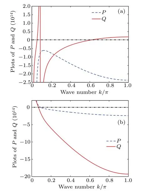
3.2.Baseband modulational instability

4.Exact and approximate modulated solitary waves in the network of Fig.2

4.1.Bright-like solitary wave
4.2.Dark solitary wave

5.Behavior of modulated waves through the network of Fig.2.


6.Conclusion
- Chinese Physics B的其它文章
- Optimal zero-crossing group selection method of the absolute gravimeter based on improved auto-regressive moving average model
- Deterministic remote preparation of multi-qubit equatorial states through dissipative channels
- Direct measurement of nonlocal quantum states without approximation
- Fast and perfect state transfer in superconducting circuit with tunable coupler
- A discrete Boltzmann model with symmetric velocity discretization for compressible flow
- Dynamic modelling and chaos control for a thin plate oscillator using Bubnov–Galerkin integral method

