Optical chirality induced by spin–orbit interaction of light in a tightly focused Laguerre–Gaussian beam
Mingchao Zhu(朱明超), Shenggui Fu(付圣貴), and Zhongsheng Man(滿忠勝),2,?
1School of Physics and Optoelectronic Engineering,Shandong University of Technology,Zibo 255000,China
2Collaborative Innovation Center of Light Manipulations and Application,Shandong Normal University,Jinan 250358,China
Keywords: tight focusing,optical chirality,spin–orbit interaction
1.Introduction
Chirality describes the mirror symmetry violation that an object cannot superimpose with its own mirror image through rotation and translation.[1]Chiral objects are prevalent in nature and can be directly judged from their geometry; in other word, geometric chirality is essentially a non-local threedimensional(3D)structural property of an object that requires a non-vanishing spatial extent.In addition,geometric chirality is a qualitative binary property.[2,3]Electromagnetic fields also have chirality,[4–25]which,by contrast,can be measured quantitatively.Optical rotatory dispersion and circular dichroism are two typically measured chiroptical phenomena.The quantification of the chirality of electromagnetic fields has been conceptualized only recently as optical chirality,[4]also known as Lipkin’s 00-Zilch, discovered decades ago.[26]It is important to emphasize that light generally exhibits chirality through circular polarization, a localized property where electric and magnetic field vectors take on a helical shape as they propagate.Therefore,optical chirality in the traditional sense cannot describe any form of chirality originating from the spatial extent of the beam.Most recently,due to the global properties of polarization and phase structure,a new type of chirality,called Kelvin’s chirality,has been proposed.[21]
With the development of modern nano-optics and photonics,non-paraxial 3D structured light fields have attracted much attention due to their fascinating properties compared to paraxial light.A key difference between paraxial two-dimensional(2D)plane wave and non-paraxial 3D structured light is that,in addition to the usually dominant transverse field, the latter also has a significant longitudinal component oriented along the direction of propagation.This leads to many extraordinary properties of non-paraxial fields, such as transverse spin angular momentum (SAM).[27–38]It is well known that SAM is closely related to optical helicity through the continuity equation.[39–41]Furthermore,the optical helicity is proportional to the optical chirality of the monochromatic field.[5]In addition, the optical field can also carry orbital angular momentum(OAM)through optical vortices.[42]Also,spin–orbit interactions have been demonstrated including, but not limited to,beam focusing through aplanatic objectives,[43,44]scattering through small particles,[45,46]excitation and scattering of surface plasmon polaritons,[47,48]and transmission through nanoapertures.[49,50]However,the effect of the interaction between the source optical vortex and helicity on the chirality in the tightly focused non-paraxial 3D structured fields is not fully understood.
In this paper,we systematically study the role and contribution of the optical degree of freedom including optical vortices and states of polarization (SoPs) of the source paraxial field on the optical chirality density of the nonparaxial field generated by tightly focused Laguerre–Gaussian beams.To this end,using Richards and Wolf vectorial diffraction method,the explicit expressions to calculate the strength vector of the 3D electric and magnetic fields are presented.The results show that the optical chirality of highly confined 3D structured field is significantly richer than that of the 2D paraxial plane wave.In addition,the structures and appearances of chirality density distributions mainly depend on the interaction between topological charge and ellipticity.Orientation, however,nearly has no effect on the chirality density distribution.The physical cause is the redistribution of the local electromagnetic polarization in 3D space associated with spin–orbit interactions.
2.Theoretical model
In paraxial 2D light,it is well known that the optical helicity is proportional to the degree of elliptical polarization:zero for linearly polarized and unpolarized light fields, and a maximum for circularly polarized light.[51]For a monochromatic paraxial source field of arbitrary ellipticity, its SoP can be described by the combination by a pair of orthogonal rightand left-handed circularly polarized basis,|R〉 and|L〉.Here we adopt a unit vector|U〉to describes the polarization state,as follows:[52–57]
where the orthonormal circular polarization basis are
aRandaLin Eq.(1) are complex coefficients indicating the fraction between the two bases.If the intensity is normalized,aRandaLcan be expressed as follows:
whereσ ∈[0,π/2]determines the fraction andφ0is the additional relative phase between the two bases.And the ellipticity of the polarization ellipse can be derived as
Normalized Stokes parameters(SPs)in the circular basis of Eqs.(1)–(5)are given by
S1,S2,andS3may be regarded as the sphere’s Cartesian coordinates of a point on a unit Poincar′e sphere(PS)as shown in Fig.1,whereS0is the radius of the PS.[58]This point can also be described by the latitude 2Θand longitude 2Φ, and their relationships are
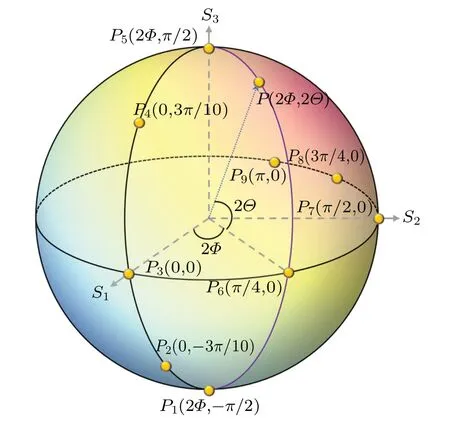
Fig.1.Poincary′e sphere representation of all possible polarization states of a monochromatic paraxial source field.
Based on Eqs.(7)–(12), we can obtain the correspondence between the parameters that determine the polarization distribution of the source beam and the coordinates on the PS
Theoretically,the optical chirality density of a monochromatic light field can be expressed as[4,26]
whereνandμare the permittivity and permeability respectively, andEandHare the real electric and magnetic fields in the time domain.Performing time averaging, the timeaveraged optical chirality density can be obtained as follows:
whereωandυrepresent the angular frequency and the speed of light, respectively, andeand?are the complex amplitude vectors of the electric and magnetic fields in the spatial domain;here,superscript asterisk indicates complex conjugation.Non-paraxial 3D structured light fields can be obtained in an aplanatic high numerical aperture(NA)objective focusing system.When the polarization distribution of the incident field is represented by Eq.(1), the corresponding 3D electromagnetic fieldseand?for any pointP(ρP,?P,zP) in the image space can be obtained using Richard–Wolf vectorial diffraction theory[59]
wherekandfare the wave number in the image space and focal length of the focusing objective lens, respectively;α=arcsin(NA/n), where NA is the numerical aperture andnis the index of refraction in the image space;φandθdenote, respectively, the azimuthal angle with respect toxaxis in the objective space and tangential angle with respect tozaxis.To reveal the optical chirality induced by interactions between source optical vortex and helicity, we employ an incident field with a Laguerre–Gaussian LG(l,p)complex amplitude distribution,wherelandpare the numbers of intertwined helices known as the topological charge and additional concentric rings.Withp=0,the functionA(θ)is given by[60]
whereβis the ratio of the pupil radius to the beam waist.
In Eq.(17),veandvhrepresent the electric and magnetic field polarization vectors in image space contributed by the input SoP; their three mutually perpendicular componentsvex,vey,andvezas well asvhx,vhy,andvhzare found to be
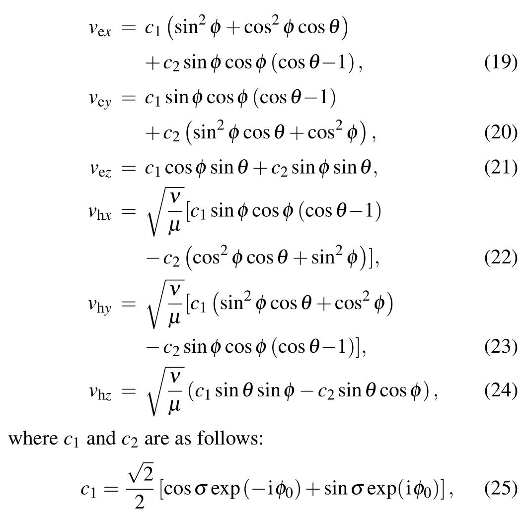
Based on the above equations,we can now study the optical chirality caused by the interaction between optical vortex and helicity of the input 2D paraxial field in focused non-paraxial 3D structured light fields.All length measurements are in units of wavelength of the input field,β=1.5,NA=1.2,n=1.33,andf=2 mm are used in the following calculations.
3.Optical chirality in the non-paraxial 3D focused field
In revealing the chirality of the tightly focused optical field caused by the interaction of helicity (local nature) and vorticity(spatial nature)of the incident optical field,it is first necessary to clarify the chirality density of the focused optical field when there is no spin in the incident optical field.To this end,we select five LG input fields with topological chargel=1 and polarization states atP3,P6,P7,P8,andP9on PS in Fig.1 as examples to study the corresponding optical chirality density distribution in the focused light field.All these input fields are linearly polarized,but have different orientations,as shown in the first row in Fig.2.From the second row in Fig.2,we can see that for all the different input fields, the optical chirality density distributions show almost the same patterns.Whenp=0,they are two different rings with different signs,and the chiral density on optical axis is obtained in the case ofl=1.Moreover, the magnitude of the optical chiral density of the outer ring is much smaller than that of the inner ring.Therefore,the orientation,as an important adjustable polarizable degree of freedom of the incident optical field, seems to have no effect on the chirality of the focused 3D field.
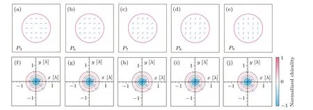
Fig.2.Polarization distributions of five LG(1,0) input fields with polarization states located at the points P3,P6,P7,P8,and P9 on the PS(upper row)and the corresponding optical chirality density distributions in the focal plane(lower row).All distributions of the optical chirality density are normalized to their common maximum.
The above results confirm the chiral character of the 3D focused fields of the input beams carrying OAM,even if these beams are linearly polarized and therefore have no SAM.Figure 3 shows the effect of the sign and size of the pseudo-scalar topological chargelon the chiral density distribution, where the five LG input fields have the same polarization state located atP3on the PS,and differ only in the topological chargel.It is clear that there is no chiral density distribution whenl=0 [see Fig.3(c)], which further suggests that the chirality of the tightly focused field is contributed by the OAM of the incident field.Then as|l| continues to increase, the optical chiral density always exhibits a centrally symmetric ring structure and the sign reverses in the radius direction.In addition,the radius of the annular optical chiral density increases.The difference is apparent when the sign of the topological charge changes,i.e.,regions of high chirality in the focal plane are replaced by regions of opposite chirality density,and vice versa.Therefore,when the input field has no SAM,the structure and appearance of the chirality density distribution depends entirely on the topological charge,i.e.,the polarization orientation has no effect on the chirality.

Fig.3.Theory-derived optical chirality density distributions in the focal plane of five different LG input fields with polarization states located at the point P3 (the incident beams are linearly polarized light) on the PS and topological charges l =-2, -1, 1, and 2, respectively.All distributions of the optical chirality density are normalized to their common maximum.
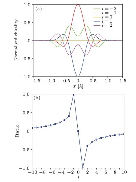
Fig.4.(a) Optical chirality density profiles along x axis in the focal plane of the same five LG input fields as in Fig.3.All distributions of the optical chirality density are normalized to their common maximum.(b)Ratio of the peak optical chirality density of each incident light field in the focal plane to the common maximum of their absolute values versus the topological charge l.
The magnitude of the optical chirality density is another important parameter in the interaction of chiral optical fields with matter.To gain more insight into the OAM-induced optical chirality shown in Figs.2 and 3,we now explore the effect of the topological chargelon the magnitude of optical chirality.Figure 4(a)shows the optical chirality distributions along thexaxis in the focal plane for the same five LG input fields as in Fig.3.All the optical chirality density distributions are normalized to their common maximum.It is clear that the peak of the optical chiral density varies considerably with the topological chargel.The specific trend is shown in Fig.4(b), which depicts the ratio of the peak optical chiral density for each incident light field in the focal plane to the common maximum of the optical chiral density for different incident light fields with respect to the topological charge.Obviously, when choosingl=1 and-1,we can obtain the highest chirality for the input linearly polarized LG beam.
For any point on the PS moving from the north pole toward the equator and then to the south pole along a fixed meridian,the ellipticity of the polarization ellipse varies from-1 to 0 and then to 1, the handedness changes from righthanded to left-handed, but the orientations remain the same.As examples,we choose five different LG(1,0)input fields with SoPs located at pointsP5,P4,P3,P2, andP1on the PS [see Fig.1]to explore the effect of spin–orbital interaction on the optical chirality density distribution in the 3D focused field[see Fig.5].The optical chirality density changes significantly in structure and appearance.Specifically,when the input field does not carry SAM, it is two rings with different signs [see Fig.5(c)].In contrast, when the input ellipticity is nonzero,a pattern of only one loop appears [see Figs.5(a), 5(b), 5(d),and 5(e)].Here,it seems that both the local handedness of the input elliptical polarization and the global handedness of the optical vortex have an effect on the sign of the optical chirality.

Fig.5.Theory-derived optical chirality density distributions in the focal plane of five different LG(1,0) input fields with polarization states located at the points P1, P2, P3, P4, and P5 on the PS, respectively.All distributions of the optical chirality density are normalized to their common maximum.
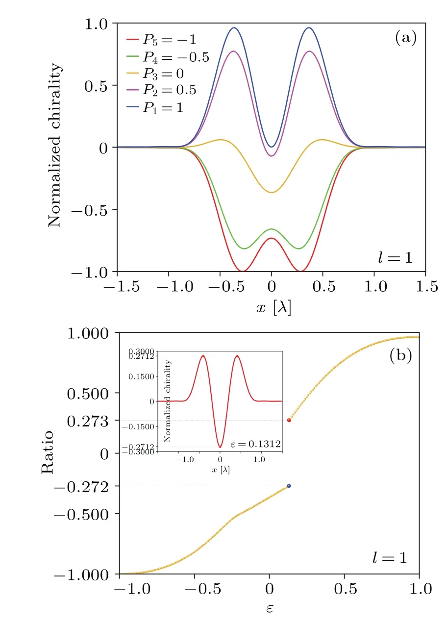
Fig.6.(a) Optical chirality density profiles along x axis in the focal plane of the same five LG input fields as shown in Fig.5.All distributions of the optical chirality density are normalized to their common maximum.(b)The ratio of the peak chiral density of each incident optical field in the focal plane to the common maximum of their absolute values versus the input ellipticity ε.
To better understand the effect of spin–orbit interactions on the optical chirality,figure 6(a)shows the optical chirality density distribution along thexaxis in the focal plane of the same five LG input fields as shown in Fig.5.All the optical chirality density distributions are normalized to the common maximum of their absolute values.It is clear that the peak of the chiral density varies accordingly with the input ellipticity.Most importantly,whether the chiral density lies on or off the optical axis can be controlled simply by a suitable ellipticity value.The effect of ellipticity on the magnitude of chiral density is shown in Fig.6(b),from which we can see that the relational curve is clearly a segmented function.By calculations, the threshold position is found at aboutε=0.1312, its corresponding optical chirality density profile alongxaxis can be seen in the inset in Fig.6(b).Under this condition,the chirality at the position of the optical axis is equal in magnitude and opposite in sign to the chirality around it.On both sides of this threshold position,the sign of the peak chiral density is opposite.
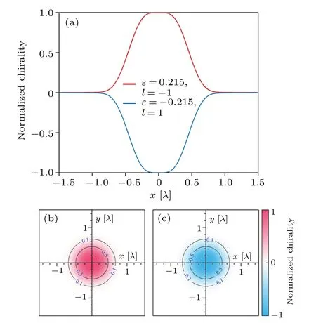
Fig.7.(a) Flat-topped optical chirality density profiles along x axis in the focal plane of two LG input fields with (ε,l)=(0.215,-1) and(-0.215,1), respectively.(b) and (c) The corresponding optical chirality density distributions in the focal plane.The distributions of these two optical chirality densities are normalized to their common maximum.
Light fields with uniform optical chirality may be useful and scarce in practical applications.Fortunately, by carefully selecting the ellipticity and topological charge of the input field,the flat-topped optical chiral density distribution can be obtained,as shown in Fig.7.Obviously,the chirality of the light field can be freely switched only by the signs of ellipticity and topological charge.In addition, the structure and appearance of the chiral density distribution remain unchanged,which may be very useful for comparing the reflection of chiral substances under different chiral light fields.The above peculiar chiral distribution originates from the polarization distribution of local electric and magnetic fields.Figure 8 shows the corresponding electric and magnetic field polarization distributions in the focal plane and their projections onto the three orthogonal planes.In general,all polarization distributions are extremely complex, because the polarization projections on thex–yandy–zplanes become solid ellipses in some regions,indicating that the rotation axes of the electric and magnetic fields are no longer parallel to thezaxis; that is to say, due to the existence of the longitudinal component,[43,44]the local polarization ellipse is not in the plane parallel to thex–yplane.For the polarization projection on thex–yplanes become solid ellipses in some regions, indicating that the rotation axes of the electric and magnetic fields are no longer parallel to thezaxis; that is to say, due to the existence of the longitudinal component,[43,44]the local polarization ellipse is not in the plane parallel to thex–yplane.For the polarization projection on thex–yplane, we can see those regions of right-handedness when (ε,l) = (0.215,-1) are replaced by left-handedness when (ε,l) = (-0.215,1), for both electric and magnetic fields,andvise versa.As a result,optical fields with opposite chirality can be obtained while the structure and appearance are maintained.

Fig.8.Theoretically calculated electric and magnetic field polarization distributions in the focal plane and their projections onto the three orthogonal planes of tightly focused two LG fields with(ε,l)=(0.215,-1)(upper row)and(-0.215,1)(lower row),respectively.Panels(a)and(c)depict the electric field polarization distributions, while panels(b)and(d)depict the magnetic field polarization distributions.Red and blue indicate that the local polarization ellipses are right-handed and left-handed,respectively.
4.Conclusions
In summary, we have studied the contributions of optical vortices and SoP of the source 2D paraxial light field on the chirality density distributions of 3D nonparaxial structured field in tight focusing.To this end, we have taken LG input field that has arbitrary SoP as an example and uses the Richards and Wolf vectorial diffraction method to derive the corresponding explicit expressions to calculate the strength vector of the 3D electric and magnetic fields.The results show that the optical chirality of highly confined 3D structured light field is obviously richer than that of the 2D paraxial plane wave.Both optical vortex and SoP of the source paraxial field have contributions to the optical chirality of the nonparaxial field, which is in stark contrast to the paraxial plane wave in classical optics.But, the structures and appearances of chirality density distributions mainly depend on the interaction between the topological charge and the ellipticity.Orientation, however, has almost no effect on the chirality density distribution.The physical origin is the redistribution of the local electromagnetic polarization in 3D space associated with spin–orbit interactions.These findings may be of help in chiral particle trapping and nanoscale chiral detection and sensing.
Data availability statement
The data that support the findings of the present study are openly available in the Science Data Bank at https://doi.org/10.57760/sciencedb.j00113.00162.
Acknowledgements
Project supported by the National Natural Science Foundation of China (Grant No.12074224) and the Natural Science Foundation of Shandong Province, China (Grant Nos.ZR2021YQ02 and ZR2020MA087).
- Chinese Physics B的其它文章
- Optimal zero-crossing group selection method of the absolute gravimeter based on improved auto-regressive moving average model
- Deterministic remote preparation of multi-qubit equatorial states through dissipative channels
- Direct measurement of nonlocal quantum states without approximation
- Fast and perfect state transfer in superconducting circuit with tunable coupler
- A discrete Boltzmann model with symmetric velocity discretization for compressible flow
- Dynamic modelling and chaos control for a thin plate oscillator using Bubnov–Galerkin integral method

