12-Point Leveling Systems for Mobile Platforms and Emergency Plans
LIU Yu,ZHANG Shuai,HE Jianhua,ZHU Miaoxin,ZENG Yi,ZHOU Li
Beijing Institute of Space Launch Technology,Beijing 100076
Abstract: With high stability,strong bearing capacity and other characteristics,multi-point leveling systems have been widely used in various industries.The mobile platform here uses a 12-point leveling system,which is mainly composed of the mechanical transmission system of the supporting arm,a hydraulic drive system and an electrical control system.The leveling is realized through the proportional lifting of the arms in four quadrants.In order to ensure the smooth conduct of launch missions,emergency plans were made for the leveling system incase of failure of a single arm.
Key words: multi-point leveling system,supporting arm,emergency operation,leveling,12-point
1 INTRODUCTION
With the development,adoption and application of plane leveling control technology,the requirements for the precision and stability of leveling control in various industries are constantly increasing.The traditional platform leveling is mostly realized by using a 4-point leveling system which consists of 4 legs,a combined hydraulic system,an electrical system and a mechanical system.However,with the application of platform leveling in the fields of vehicle,satellite TV receiver,bridge erection equipment,medical detection platforms,missile launcher,etc.,the traditional platform leveling method can no longer meet the requirements.
Many traditional mobile devices have level requirements for the installation surface of the equipment when the equipment is in operation,and the horizontal plane will provide a detection benchmark for the equipment.For small equipment,the old axiom is to determine a plane according to three points,and obtain a horizontal datum by adjusting the three fulcrum points on the mounting surface.For a platform of relatively small geometric size,the four-point leveling system can be used to achieve the adjustment of the plane.However,a large multi-point platform with heavy load and more than 6 points,especially in terms of low rigidity of the equipment support surface,it is difficult to obtain a good horizontal datum through this method based on the manual leveling technology which is time-consuming and laborious and a hydraulic leveling system.In addition,affected by sloping landform and geological structures,it is difficult to level the points through observing the level in manual when there are multiple points for supporting large equipment and heavy loads.The hydraulic leveling system usually needs collaboration with the electronic control system to conduct accurate control due to the coupling between different fulcrum points in the multi-axis leveling system and effectively virtual legs in the coupling plane.It can be seen that a multi-point hydraulic leveling system with an electronic control system plays a very important role.
The launch vehicles employed in China all require vertical adjustment during mission preparation.A level measuring instrument is installed on the tail of the first and second sub-stages (or third sub-stage) of a launch vehicle respectively,and its output is transmitted to a level indicator in the ground equipment room through a cable to monitor the vertical attitude.The vertical adjustment is a part of the initial alignment work,whose purpose is to adjust the initial vertical attitude of the vehicle to meet the requirements of attitude accuracy control.The vertical adjustment is mainly achieved by adjusting the components that supported on the bottom of the carrier rocket.During operation,the vertical degree of the vehicle is adjusted by adjusting the phase height of jacks or supporting arms at different positions on the platform according to the level measurement at that junction.In order to ensure the correct takeoff angle,the load is usually tested for levelness after the completion of the final assembly and during the fuel filling process,and the leveling adjustment is carried out in time to ensure that the overall levelness is kept within a reasonable range,and the load support arms are evenly distributed.In order to ensure that the fulcrums of the vehicle are stressed evenly in the process of perpendicular adjustment,it is necessary to control the fulcrums of the vehicle in the same plane by multi-point linkages with the platform.Due to influence factors such as the manufacturing variation,uneven deformation,there may be a situation where there are large forces on a supporting arm,so it is necessary to adjust the supporting arm separately to evenly distribute the load and avoid damage to the structure.If the supporting arm fails to move,it will result in the load being insufficient to complete the leveling and the launch mission will be delayed.Therefore,the support arms play a very important role,and emergency plans should be made in case of failure of a supporting arm.
2 COMPOSITION OF 12-POINT LEVELING SYSTEM
According to the stability and reliability requirements of the leveling process,the platform leveling system is designed as a 12-point leveling system,which consists of support arm structural components,hydraulic levesing system,and electrical control system.The leveling precision and leveling procedure of the hydraulic leveling system are controlled by the electronic control system.The three-dimensional (3D) structure of the system is shown in Figure 1.

Figure 1 3D outline diagram of 12-point leveling system
2.1 Supporting Arms
The supporting arms,which are used to support the weight of the vehicle after filling,participate directly in the leveling process of the vehicle before and after filling,they fix the vehicle during hoisting and transportation,and can adapt to the radial and circumferential deviation of the vehicle during hoisting.The supporting arms,as shown in Figure 2,are composed of a supporting disc,a wind-proof mechanism,a nut,a force measuring device,a height measuring sensor etc.The supporting arms are installed on the upper body of the platform through a lower seat flange,where the load is mainly applied by the supporting disc,force sensor,nut and screw,and the lifting force is mainly achieved by the hydraulic motor which drives the reducer and drives the screw and nut composed of spiral transmission structure.
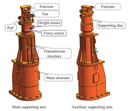
Figure 2 The supporting arm structures
The supporting arms adopt the transmission principle of a screw drive,which is composed of key components such as a hydraulic motor,a reducer,a screw,a nut and an inner sleeve.Figure 3 shows the transmission route of force and movement when the supporting arm is raised and lowered.When operating,the hydraulic motor is used as power source of the supporting arms and the power is transmitted to the screw through the reducer,and the screw transmits the force to the inner sleeve through the nut engaged with it.Through the guiding function of the flat key and the copper key,the relative rotation of the nut and screw is converted into the lifting movement of the inner sleeve,and the force sensor,the supporting disc,the wind-proof mechanism,and the fulcrum are connected with the inner sleeve through the force sensor seat,so as to realize the lifting.

Figure 3 The transmission route of the force and movement when the supporting arm is operating
2.2 Hydraulic System
The arm control circuit is provided with one arm control valve box,which is mainly composed of a proportional direction valve group,an oil inlet valve group,valve box.The proportional direction valve group is composed of a proportional direction valve,a pressure compensator,an electromagnetic reversing valve,and a hydraulic control logic valve.The layout of the arm control valve box is shown in Figure 4.
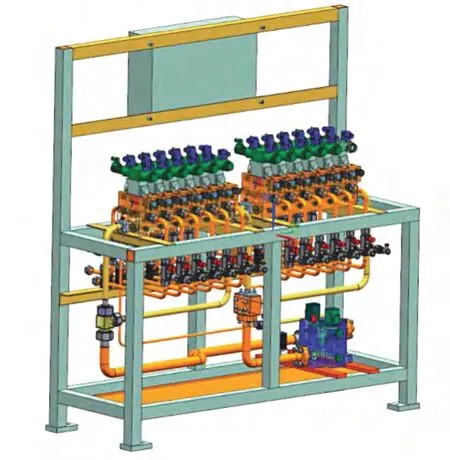
Figure 4 Layout of supporting arm control valve box
12 proportional direction valves,respectively,control the rising and falling action of 12 supporting arms,where the speed can be adjusted within the maximum flow range.The pressure compensator ensures that the control speed of the supporting arms is not affected by the load,and the 12 supporting arms support the vehicle as required.The leveling of the vehicle and the load control are realized through a displacement and load closed-loop control system.
The hydraulic system uses the control loop with the switching device as the backup of the control loop for the supporting arms.In order to avoid mutual influence with the emergency backup loop and the operation loop in case of failure,the positive and negative cavities of each operating loop are set with normally open liquid control logic valves.The open and close states of the two logic valves on the positive and negative cavities of the same working loop are controlled by an electromagnetic reversing valve on the switching device.
2.3 Electronic Control System
The electronic control system is composed of a manual controller,an automatic controller,a PLC controller,a displacement sensor,a force sensor,a pressure and a flow signal amplifier,a proportional relief valve,and a proportional flow valve,a pressure sensor,a level sensor,as shown in Figure 5.
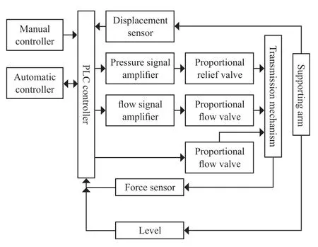
Figure 5 Schematic diagram of electric control system
The output end of the manual controller and the automatic controller are connected with the input end of the PLC controller.The output end of the PLC controller is connected with the input end of the pressure amplifier and the flow amplifier.The output end of the pressure amplifier is connected with the input end of the proportional pressure valve.The output end of the probportional pressure valve and the output end of the proportional flow valve are connected with the input end of the transmission mechanism,respectively.The output end of the PLC controller is connected with the input end of the transmission mechanism through a solenoid valve.The output end of the transmission mechanism is connected with the arms and the force sensor,respectively.The displacement sensor is connected to the PLC controller.Similarly,the force sensor and level sensor are connected with the PLC controller.
When the electronic control system operates,the PLC first sends a control signal to the hydraulic system.The hydraulic system activates the control of lifting speed and lifting direction of the arm after receiving the pressure and flow control signals.The displacement sensor,force sensor and level sensor in the arm lifting process,constantly collect the corresponding feedback from the transmission mechanism,and send the signals back to the PLC controller,that adjusts the arm control signal to make fine adjustments according to the feedback signals.If the feedback signals exceed the preset limits,then a system alarm is issued to perform an emergency stop.
In the leveling process,the tilt signal of the vehicle measured by the inclination sensor,the position signal in the vertical direction of the supporting arms measured by the displacement sensor,and the load signal in the vertical direction of the supporting arms measured by the force sensor are input to the electronic control system.After processing the input data and selection of the appropriate response,the computer and controller (manual judgment in manual mode) send the corresponding control signal to the hydraulic system to drive the movement of the supporting arms.Until the leveling requirements are met,the load of each arm (only the vertical load) is monitored in real time during the leveling process to ensure that it is within the required range.
3 PRINCIPLE OF LEVELING
According to the requirements of a launch mission,12 supporting arms are distributed as shown in Figure 6,1 main supporting arm and 2 auxiliary supporting arms are considered a group,called a quadrant,to achieve the support of a booster stage vehicle.The core stageof the vehicle is hung on the four booster rocket bodies,so that the 12 supporting arms can support the whole vehicle.
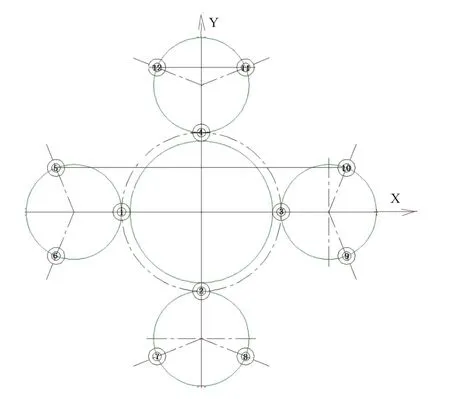
Figure 6 Layout of 12 supporting arms
As shown in the Figure 6,the No.1,No.2,No.3 and No.4 arms are evenly distributed in turn on the circumference with the center of the platform as the center of the circle,which is defined as the first circle,and the center angle between the two adjacent arms is 90°.The other arms of No.5-No.12 are successively distributed on the circumference with the center of the platform as the center of the circle in the counterclockwise direction,and the circumference is defined as the second circumference,the diameter of the second circumference is greater than that of the first circumference.Each quadrant is named after the main supporting arm and is named as quadrant I-IV respectively.The booster leveling is set in the center of each quadrant,and the core leveling is set in the core stage.A total of five groups of levels are set,and the weighted levelness of the vehicle is calculated according to the weight of each level,which is used as the criterion of whether or not the leveling is completed.Since the plane leveling needs to be adjusted in two directions orthogonal to each other,usually we select the cross section of the center of the circle to analyze the plane levelness,so we set the direction of the first arm and the third arm as the X-axis,and take the diameter direction of the fourth arm and the second arm as the Y-axis.Therefore,the left side of the Y-axis is the first quadrant I,the right side of the Y-axis is the third quadrant III,the lower side of the X-axis is the second quadrant II,the upper side of the X is the fourth quadrant IV.
Where,the lateral inclination angleαis the horizontal inclination angle weighted value of the X-axis,the weighted value is weighted by the five horizontal inclination sensors,called the lateral inclination angle,when the quadrant I is higher than the quadrant III,the lateral inclination angleαis positive.Now by setting the longitudinal inclinationβas the horizontal inclination weighted value of the Y-axis,the weighted value by the weighted value of the five horizontal inclination sensors,called the longitudinal inclination,occurs when the quadrant II is higher than the quadrant IV,the longitudinal inclinationβis positive.The specific leveling steps are as follows.
1) Check whether the initial load meets the requirements.According to the display value of the force measuring sensor of the arms,check whether the load of each arm is within the range of the upper and lower limits of the allowable load,and continue to the next step if the requirements are met.Otherwise,load adjustment is made by raising or lowering the corresponding arm to make the load of each arm meet the requirements;
2) Determine the leveling direction.First of all,according to the weighted value of 5 horizontal inclination sensors we determine whether the lateral inclination angleαand longitudinal inclination angleβare within the required ranges.If so,the requirements are met and the leveling is complete.If not,compare the absolute value of the lateral inclination angleαand longitudinal inclination angleβ,priority is given to adjust the direction of the absolute value of the large angle,resulting in the subsequent plane flipping multi-point leveling method where |α| > |β| as an example to illustrate.If the lateral inclination angleαis positive,the rule becomes I down III up leveling,if the lateral inclination angleαis negative,it becomes I up III down leveling;
3) Lateral inclinationαadjustment process,here the platform is turned over along the Y-axis until the lateral inclination angle absolute value |α|≤c and the loads of 12 arms meet the requirements,so the leveling stops;
4) Next,βleveling is conducted until the absolute value of longitudinal inclination |β|≤c and the load of 12 arms meet the requirements,thenβleveling is stopped;
5) Finally we determine whether or not the accuracy of X-x and Y-y direction meet the requirements,if meet the requirements,the leveling is stopped,otherwise we return to step 2,and carry out the next round of leveling.
The specific method in the above steps 3 and 4: takeα> c as an example,c is positive,determine the I down III up leveling method,delimit by the Y-y axis,reduce the quadrant I side 5 arms,raise the quadrant III side 5 arms.In the leveling process,the reading of 5 horizontal inclination sensors are monitored until the weighted value meets the requirements.The display value of the arm force measuring sensor is monitored at the same time.If the load of one arm reaches the set limit load,the leveling is suspended.After the load of the arm is adjusted to the required range,the program returns to the initial state of step 2 to re-determine the leveling direction until the weighted value of the 5 horizontal inclination sensors meet the requirements.The same is true forβ-direction leveling.
It should be noted that no matter if the X-x axis is used as the tilting axis for the lifting adjustment of the quadrant I and the quadrant III,or the Y-y axis for the lifting adjustment of the quadrant II and the quadrant IV,the 2 arms on the tilting axis are not moved,while the remaining 10 arms are synchronously controlled according to the position ratio.
4 FAILURE PREPLANS
Since the leveling action is part of the countdown process,when a supporting arm fails to operate,the load cannot be leveled and the launch mission has to be delayed.Therefore,it is necessary to analyze the possible failure causes of the supporting arm,so as to develop an emergency plan in case of a failure.According to the composition of the 12-point leveling system,there are three types of reasons for a failure:
1) Mechanical system stuck.The mechanical transmission structure breaks due to fatigue,other reasons,or because of the excess material entering the transmission system,so it cannot drive normally.The mechanical system is less likely to be stuck,but it is not possible to complete troubleshooting in a short time after a failure;
2) Hydraulic system failure.The reasons failure for of the hydraulic system that lead to the abnormal operation of the supporting arm usually include: the solenoid valve is stuck and cannot reverse normally,the oil source is faulty and cannot supply oil,and the hydraulic motor is stuck.However,the hydraulic system oil source and valve group have a backup,the hydraulic motor usually does not become stuck,so the probability of failure of the hydraulic system is low.In addition,even if the hydraulic system fails,it can be eliminated by replacing the valve and other measures,so the troubleshooting time is short;
3) Electronic control system failure.The reasons for failure of the electronic control system usually include: CPU failure,power failure,a cable short-circuit or other short-circuit.For this reason the electronic control device of the 12-point leveling system is equipped with a backup device,and the cable is generally checked before the mission,so the probability of failure of the electronic control system is also low.In addition,the time for replacement of the electronic control system when there is a failure is short,so we can achieve rapid troubleshooting.
To summarize,the 12-point leveling system design cannot solve problems quickly when a mechanical delay occurs,so the risk is high,hence it is necessary to have a backup plan for mechanical delay.As the arm drive structure is located inside the arm and isolated from the outside world,there is usually no mechanical sticking problems,and there is only a small probability of an issue with the arm drive structure or motor shaft.
Vertical monitoring and fine adjustment of the vehicle usually exist in the critical period near the mission.Considering the urgency of the mission process and the safety of the vehicle,if a single supporting arm fails to operate at this time,it is usually impossible to carry out fundamental troubleshooting and replacement.It is only appropriate to use the faulty supporting arm as the leveling center point,and the remaining 11 supporting arms surround the faulty supporting arm.The adjusting height value is calculated according to the proportional relationship between the side lengths of similar triangles,and a proportional control voltage is applied to the proportional direction valves of 11 supporting arms respectively,so as to realize the proportional height adjustment speed of 11 supporting arms,enabling the leveling of the vehicle with a faulty single supporting arm.
As the load is adjusted regardless of the quadrants I,III or II,IV,the leveling principle is the same,and the same turning axis is flipped,no matter which side is high,so the leveling strategy is similar.Figure 7 takes the quadrants II and IV leveling as an example,first of all,we assume the following settings:
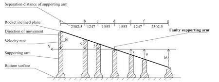
Figure 7 Example of arm failure mode
1) Single arm failure occurs in the second quadrant;
2) The platform in the II-IV quadrant direction (Y-axis) is quadrant IV high and quadrant II low;
3) Place the platform plane over the center of the circle and perpendicular to the X-axis.The section of the platform is analyzed for tilt;
4) For ease of description,the No.11 and No.12 arm is the a arm,the No.4 arm is the b arm,the No.5 and No.10 arm is the c arm,the No.1 and No.3 arm is the d arm,the No.6 and No.9 arm is the e arm,the No.2 arm is the f arm,and the No.7 and No.8 arm is the g arm.
The failure mode in Figure 7 shows that when the d arm fails,the d arm is used as the fulcrum,and the other arms move up or down around the d arm,which is specifically represented as arms a,b,and c move down,and arms e,f,and g move up.Their operating speeds form a proportional relationship according to the similarity triangle,so it is necessary to adjust the proportional voltage signal relationship of the proportional direction valve for achieving leveling in a fault state.Under other tilt angles and other support arm failure states,the leveling method is similar to Figure 7.
5 CONCLUSION
Due to good load-bearing capacity and high reliability,multi-point leveling systems have been widely used in different industries.At present,the launch platform of the Long March 5 rocket also applies the principle of multi-point leveling.This article introduces the composition,leveling principle,and fault plan of the 12-point leveling system,focusing on the mechanism of high-precision leveling of the 12-point leveling system.Based on its leveling process and potential risks and faults,an emergency fault plan is explored to ensure the normal launch of the rocket in fault mode.At the same time,the design concept of the 12-point leveling system in this article can provide reference for other multi-point leveling fields,and the fault emergency plan has a certain degree of innovation,which can increase the experience of use in the field of multi-point leveling.
- Aerospace China的其它文章
- Safety Analysis of Launch Vehicle Software Systems
- Cooling Technology for Thrust Chamber of LM-5B LOX/kerosene Engine
- Research on Frequency Improvement for LOX/kerosene Rocket Engine-Servo Loop
- Design of A Hot Redundant Communication Network for Drive Control Systems of Mobile Launch Platforms
- Dynamic Analysis of Launch Vehicle Piping Systems
- Structural Analysis and Life Prediction of Thrust Chambers For Hydrogen-Oxygen Rocket Engines

