Evaluation of heavy roller compaction on a large-thickness layer of subgrade with full-scale field experiments
Shu-jian WANG ,Hong-guang JIANG ,Zong-bao WANG ,Yu-jie WANG ,Yi-xin LI, ,Xue-yu GENG ,Xin-yu WANG,Kai WANG,Yi-yi LIU,Yan-kun GONG
1School of Qilu Transportation,Shandong University,Jinan 250002,China
2Shandong Hi-Speed Engineering Test Co.,Ltd.,Jinan 250002,China
3Shandong High-Speed Jiqing Middle Line Highway Co.,Ltd.,Weifang 261599,China
4School of Engineering,University of Warwick,Coventry CV48UW,UK
5Shandong Hi-Speed Group Co.,Ltd.,Jinan 250002,China
Abstract: Subgrade construction is frequently interrupted due to precipitation,soil shortage,and environmental protection.Therefore,increasing the thickness layer is required to reduce construction costs and to allow highways to be placed into service earlier.This paper presents a series of full-scale field experiments evaluating the compaction quality of gravel subgrade with large-thickness layers of 65 cm and 80 cm using heavy vibratory rollers.An improved sand cone method was first proposed and calibrated to investigate the distribution of soil compaction degree across the full subgrade depth.Results showed that dynamic soil stresses caused by the heavy vibratory rollers were 2.4–5.9 times larger than those of traditional rollers,especially at deeper depths,which were large enough to densify the soils to the full depth.A unified empirical formula was proposed to determine the vertical distribution of dynamic soil stresses caused by roller excitation.It was demonstrated that soils were effectively compacted in a uniform fashion with respect to the full depth to 96.0%–97.2%and 94.1%–95.4%for the large-thickness layers of 65 cm and 80 cm within 6 or 7 passes,respectively.Empirically,linear formulae were finally established between soil compaction degree and the subgrade reaction modulus,dynamic modulus of deformation,dynamic deflection,and relative difference of settlement to conveniently evaluate the compaction qualities.It is demonstrated that increasing the thickness layer by means of heavy rollers can significantly reduce the cost and time burdens involved in construction while ensuring overall subgrade quality.
Key words: Highway subgrade;Heavy vibratory roller;Thickness layer;Dynamic soil stress;Compaction degree;Compaction quality control
1 Introduction
Subgrade should have sufficient compaction de‐gree and bearing capacity to support upper structures and vehicles.However,in China,subgrade construc‐tion is frequently interrupted due to precipitation,soil shortage,and environmental protection.Consequently,the remaining time is quite limited for subgrade engi‐neering which is commonly compacted in layers of 30-cm thickness or less.Therefore,it is imperative to accelerate the construction schedule of subgrade engineering.Although rollers of more than 30 t have gradually been introduced in field work,making it possible to compact soil layers thicker than 30 cm,efficient technologies and credible detection methods are still not reliable for guaranteeing the soil compac‐tion quality of the full depth of subgrade.
To increase the thickness layer of subgrade com‐paction,construction machines with large excitation force have been manufactured.Kim and Chun (2016)inferred that impact rollers seemed to have more potential for use in the final compaction of thicker layers.Through rapid impact construction(RIC),Mo‐hammed et al.(2013) found that the compaction de‐gree of silt sand was improved from 45% to 70%with the maximum thickness of 5.0 m.Ghanbari and Hamidi (2014) showed that RIC strongly improved the soil up to 2 m in depth and commonly influenced the soil up to the depths of 4 m.However,the RIC method generates discrete tamping points,which make it difficult to ensure uniformity of subgrade compac‐tion.Xu et al.(2014)validated the performance of the impact roller (IR) technology.To compact subgrade continuously,impact roller compaction (IRC) was successfully applied to subgrade compaction due to its larger impact force.Although the IRC method is capable of compacting deeper soils,the compaction degree of soils within the upper 0.5 m was always non-uniform.Chen et al.(2021) validated the devel‐oped numerical scale model against a field study using the full-size rolling dynamic compaction (RDC)module.Nowadays,heavy-weight (more than 26 t)vibratory roller compaction (VRC) has been widely used in subgrade construction.With larger eccentric force and deeper reinforcement depth,it is possible to compact subgrade with greater thickness.Mooney and Rinehart (2007) pointed out that the influencing depth of VRC was affected by soil stiffness and the coupled dynamic effect of roller and soil.Moreover,Wers?ll and Larsson (2013) conducted 85 small-scale tests and found that there was a distinct frequency dependence,implying a significantly improved com‐paction effect close to the compactor–soil resonant frequency.Wers?ll et al.(2017) conducted a fullscale test and found that lower compaction frequency significantly reduced the required engine power and thus fuel consumption and environmental impact,while increasing the lifespan of the roller.Wers?ll et al.(2018) confirmed that the lower frequency was more efficient for compaction and that utilizing resonance in the roller-soil system could reduce the number of passes.Moreover,Wers?ll et al.(2020) proposed that crushed gravel 100 cm thick could be dramatically better compacted by a vibratory roller under the reso‐nant frequency of the coupled compactor-soil system,when the efficiency increased by about 20%.Chen et al.(2019) studied the construction technology of rock materials using a roller of 32 t and pointed out that those materials were effectively compacted with‐in the depth of 90 cm.Furthermore,the automatic fre‐quency conversion compaction technology was suc‐cessfully applied on the construction site,and a vibra‐tory roller of 20.9 t could effectively reinforce crushed rock of 1 m.
Since the maximum detection thickness of com‐paction degree stipulated in the Chinese specification is less than 400 mm,it is necessary to propose a reli‐able testing method to suit larger-thickness layers.Chen et al.(2014)pointed that in-situ measurement of full-scale model tests can be used to study the distri‐bution of dynamic stress in the subgrade.Cui (2010)found that the pore pressure and soil stress were stabi‐lized with the number of compactions and correlated well with the compaction state.Xu (2021) combined geological radar with the sand filling method and de‐tected the compaction state along the depth.Based on the analysis of dynamic impact and vibration waves,Zhang et al.(2021) proposed that the layered inter‐face settlement(LIS)of the subgrade changed signifi‐cantly at the bounded depth of 0.9 m.Li et al.(2020)proposed that the resistivity method could be used for moisture detection,while the polarizability method was suitable for compaction measurement.Yuan et al.(2020)conducted electrical measurements in the labo‐ratory and found an exponential/logarithmic relation‐ship between the water content,compaction degree,and polarizability.Wu et al.(2022) pointed out that the critical moisture content of soils with large parti‐cle size is usually lower than that with small parti‐cle size.Generally,the falling weight deflectometer(FWD) system could reflect the compaction state of soil by measuring its impact load and the deflection of the plate.Sulewska (2012) pointed out that the compaction degree of non-cohesive soil could be well detected by the light falling weight deflectometer(LFWD) method.Vennapusa and White (2009) pro‐vided a review of basic principles and of the light weight deflectometer (LWD) equipment of differ‐ent manufacturers.Fujyu et al.(2004) introduced the techniques used in the load and the deflection measurements in the LFWD system.Vennapusa et al.(2012)proposed that the influence depths of the FWD and LWD were 60 cm and 30 cm,respectively.
Current research is mainly focused on the con‐struction technology of VRC and the measurement of modulus or deflection at the subgrade surface.Al‐though the VRC method can increase the subgrade thickness layer,the uniformity of the compaction de‐gree along subgrade depth as well as its relationships with other indices has been rarely evaluated.In this study,a series of full-scale field experiments were car‐ried out on thickness layers of 65 cm and 80 cm with heavy roller compaction,in comparison to the tradi‐tional thickness layer of 30 cm.The sand cone method was improved to determine the soil compaction degree for the full subgrade depth.Soil pressure sensors were embedded at different depths to record the dynamic soil stresses caused by moving rollers.An empirical formula was proposed to determine the distribution of dynamic soil stresses along soil depths.To assess the compaction quality,the subgrade settlement (S),sub‐grade reaction modulus(K30),dynamic modulus of de‐formation (Evd),and dynamic deflection (L) were also measured after each roller pass.Relationships be‐tween these indices were further analyzed to reliably evaluate the effects of heavy roller compaction on a large-thickness layer of subgrade.
2 Full-scale field experiment
2.1 Materials
To evaluate the influence of the thickness layer on the compaction effect of the subgrade soil,a fullscale field experimental program was designed and tested on the Weifang-Qingdao Expressway in Shan‐dong Province,China.Sieve tests were carried out to determine the particle distribution characteristics of the subgrade filling material as shown in Fig.1.The filling material was poor-graded gravel (GP) with coefficient of uniformityCu=107.7 and coefficient of curvatureCc=0.15.
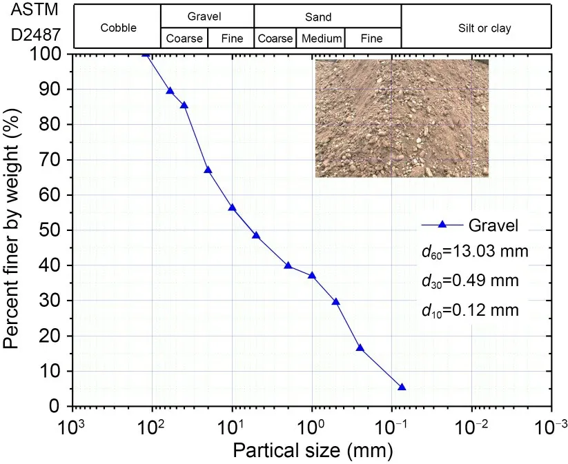
Fig.1 Particle distribution characteristics of the subgrade filling. d60, d30,and d10 denote the particle sizes,the mass percents of which are smaller than 60%,30%,and 10%,respectively
Due to the dimension limitation of the testing tube relative to the maximum particle size of the fill‐ing material,the maximum dry density (bulk density)was determined by the similar gradation method with four different particle-size ratios of 2,3,6,and 12.Each group of the dry filling material was prepared by the vibration compaction method to reach its maxi‐mum dry density as shown in Fig.2a according to the standard.Then a logarithmic formula could be fitted based on the experimental values of the maximum dry density (ρ) with four different particle-size ratios (Mr).Based on this empirical formula,as shown in Fig.2b,the maximum dry density of the field filling material was determined to be 2.216 g/cm3with the particle-size ratio equal to 1.0.
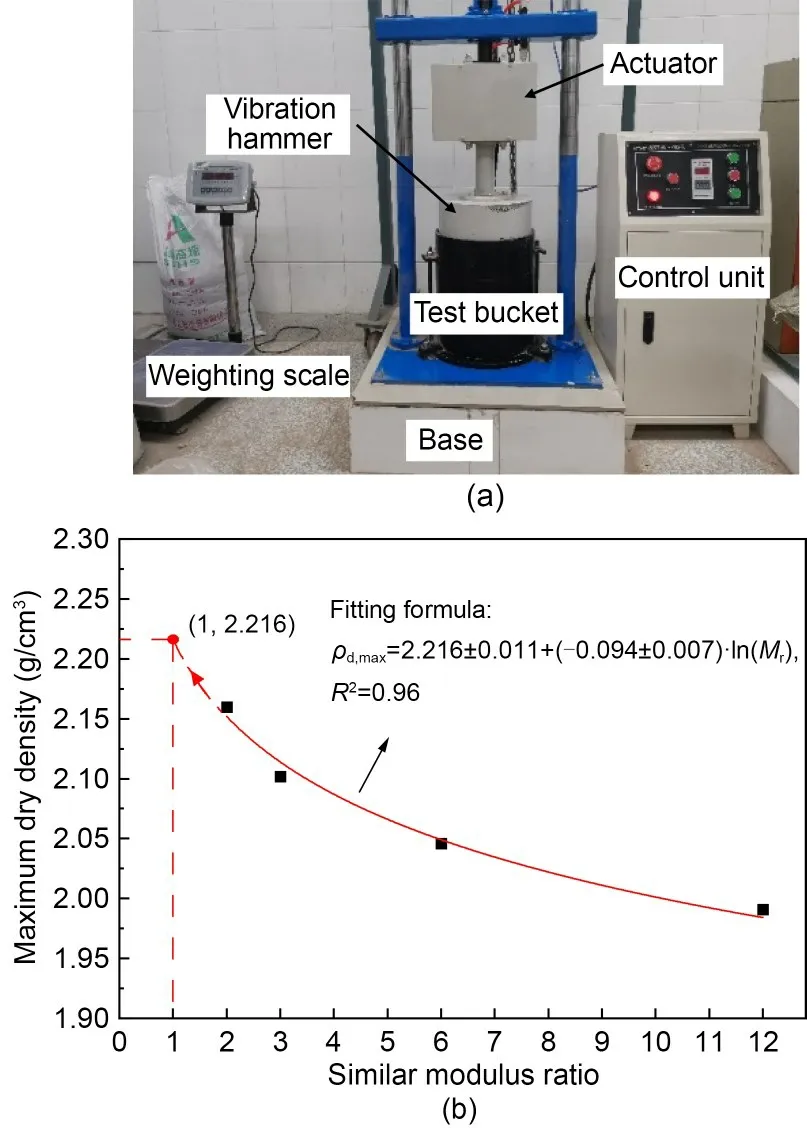
Fig.2 Maximum dry density test of the subgrade filling:(a) surface vibration compaction instrument;(b) similar gradation method
2.2 Program of the full-scale field experiment
The full-scale field experiment was carried out in three test sections with different thickness layers.Two large-thickness layers of 65 cm (TS-65) and 80 cm(TS-80) were selected for evaluating the subgrade compaction quality and the conventional thickness layer of 30 cm(TS-30)was used as the control group.Each test section was 200 m long and 50 m wide,and was compacted with the same subgrade filling mate‐rial(GP).Two types of smooth-drum vibration roll‐ers (Xugong XS263J and Zhongda YZ362,China)were adopted to optimize the compaction technology combination.The main roller technical parameters are shown in Table 1.The total weight of the Xugong XS263J Roller is 26 t with a drum width of 3.28 m,which can provide vibration frequencies of 27 Hz and 32 Hz,corresponding to the exciting forces of 290 kN and 405 kN,respectively.The roller of Zhongda YZ362 has a large-tonnage weight of 36 t with a drum width of 3.4 m.Since this roller is equipped with the stepless frequency modulation hydraulic system,it can provide vibration frequencies from 0 to 28 Hz.During the field compaction,two commonly used fre‐quencies of 21 Hz and 24 Hz were selected to output 500 kN and 700 kN excitation forces,respectively.
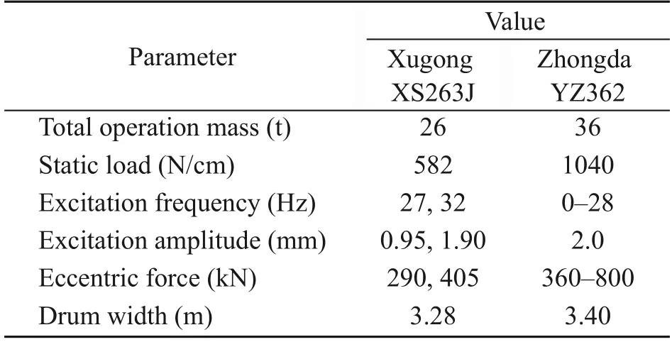
Table 1 Main roller technical parameters
To satisfy the required thickness layer of each compaction layer,the volume of subgrade filling ma‐terial was first estimated per unit grid of 1 m×1 m.Therefore,the test section was gridded and filled with the required volume of subgrade filling material.Steel bars were embedded around the boundaries of the sub‐grade as a reference to the target thickness,which was implemented by the grader machine.The rolling pro‐cess was then carried out to compact the subgrade fill‐ing material with predefined excitation forces and roll‐ing passes at three test sections.For the cases of TS-65 and TS-80,the soil layer was first pre-compacted by a XS263J Roller to provide a relatively firm working surface,otherwise the roller with higher excitation force was likely to be trapped in the thick uncom‐pacted soil layer.Then the soil layer was compacted by two passes of the YZ362 Roller of 700 kN,fol‐lowed by two passes and three passes of 500 kN exci‐tation forces for the TS-65 and TS-80 at the speed of 1.0 m/s,respectively.For comparison,the soil layer of TS-30 was first compacted by two passes of the YZ362 Roller of 500 kN,followed by three passes of the XS263J Roller of 290 kN.Finally,the rolling surface was flattened by the grader machine and complementally compacted by the XS263J Roller without vibration.
Soil pressure caused by rollers is considered as a direct parameter to reflect the compaction influencing depth.During rolling compaction,dynamic soil stresses along the layer depth were measured by soil pressure transducers,which were calibrated in the laboratory before installation in the full-scale field experiment.Fig.3 illustrates the configurations of the embedded soil pressure transducers at different depths with a spacing of 0.5 m in the longitudinal direction.The pe‐riphery of soil pressure transducers was filled with compacted standard sand to uniformly transmit the roller induced dynamic soil stresses.A data acquisi‐tion instrument was adopted to record the time-history information of dynamic soil stresses with a sampling frequency of 1000 Hz.
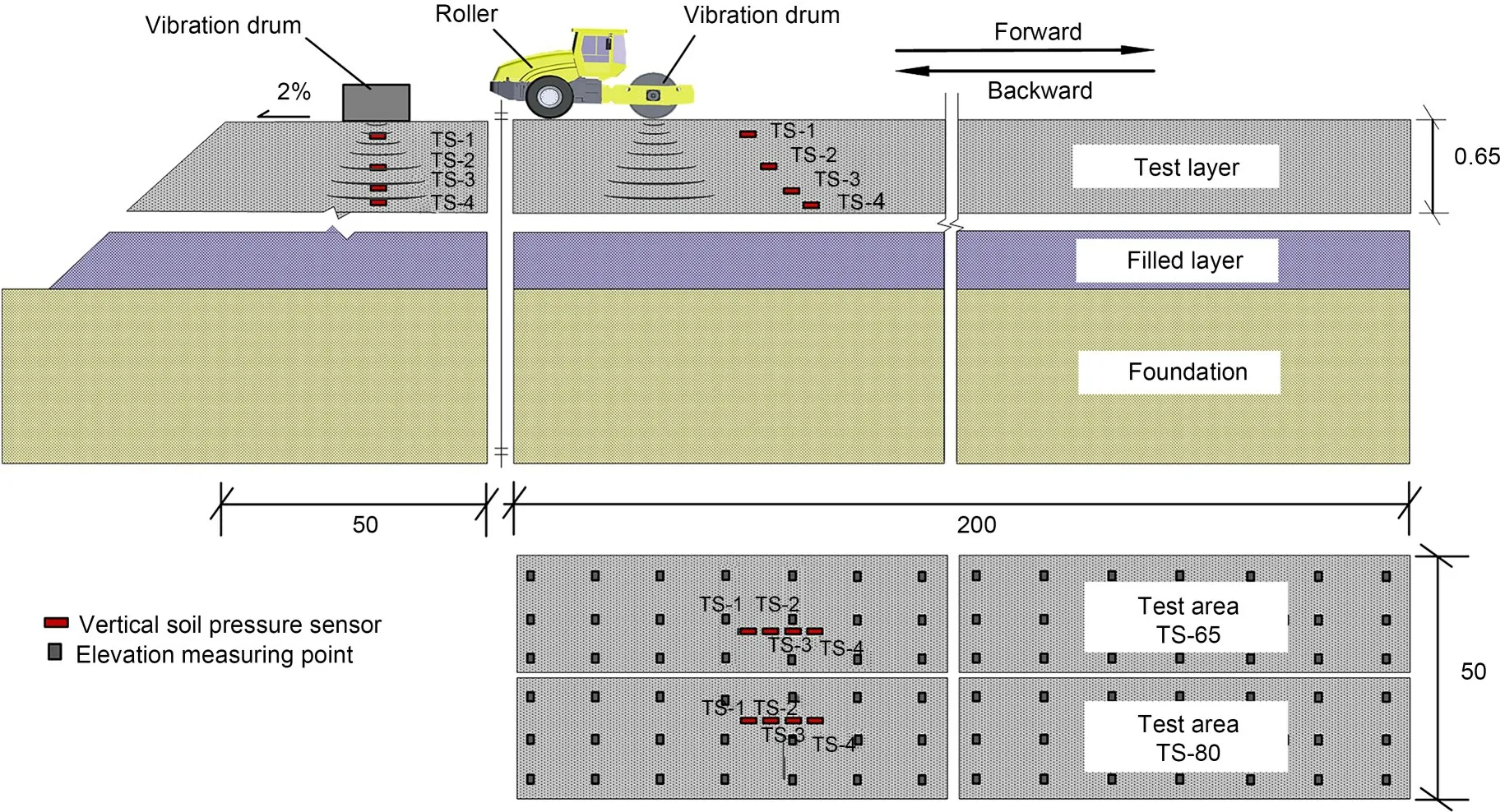
Fig.3 General view of test sections:cross section and longitudinal section(unit:m).TS-i(i=1,2,3,and 4)represent the soil pressure sensors located at four different depths,respectively.TS-65 and TS-80 represent the test sections with lift thicknesses of 65 cm and 80 cm,respectively
To assess the compaction quality,the subgrade settlement (S),compaction degree (K),subgrade reac‐tion modulus (K30),dynamic modulus of deformation(Evd),and dynamic deflection (L) of each compacted layer were measured after each roller pass.The com‐pactness tests for each compacted layer were conduc?ted with an improved sand cone method.Details about the improved sand cone method are described in Data S1 of the electronic supplementary materials(ESM).
In order to investigate the distribution of soil compactness along the compacted layer for the thick‐ness layers of 65 cm and 80 cm in the field experi‐ments,sand cone tests were conducted at three differ‐ent depths of the compacted layer for each roller pass,i.e.,the upper layer (0–1/3 depth from the compacted layer surface),middle layer (1/3–2/3 depth),and bottom layer(the remaining 1/3 depth from the com‐pacted layer bottom).To facilitate the field measure‐ment,the soil compactness at three different depths was implemented within the same testing pit.Then the soil compactness can be calculated by

wherei=1,2,and 3,represent the upper,middle,and bottom layers,respectively;mfd,iis the dry mass of the subgrade filling at theith layer;ρd,maxis the maximum dry density of the subgrade filling;ms,iis the mass of falling sand at theith layer;ρs,iis the density of falling sand at theith layer,which is detailed in the ESM.
The static rigidity of the compacted subgrade was evaluated by the subgrade reaction modulus,K30,via a rigid plate of 30 cm in diameter.The applied stress and induced displacement were recorded during the staged loading and theK30value was determined by the applied stress by the following formula:

whereσsis the applied stress on the rigid plate corre‐sponding to the displacement of 1.25 mm,MPa;?lis the displacement valued 1.25 mm here.The dynamic rigidity of the compacted subgrade was further evalu‐ated by the dynamic deflectionLusing the FWD and the dynamic modulus of deformation using the porta‐ble falling weight deflectometer(PFWD).
3 Test results and analysis
3.1 Dynamic soil stress
Typical time history and frequency spectrum curves of measured dynamic soil stresses caused by the moving roller are illustrated in Fig.4,taking the YZ362 Roller vibrating at 24 Hz at the depth of 37 cm as an example.Two main peaks in Fig.4a correspond to the vibratory drum and the following non-vibratory wheel,with the maximum values of 0.46 MPa and 0.07 MPa,respectively.Considering the peak value of 24 Hz from the frequency spectrum analysis in Fig.4b,it can be found that the compaction energy is mainly contributed by the drum vibration rather than its static weight.
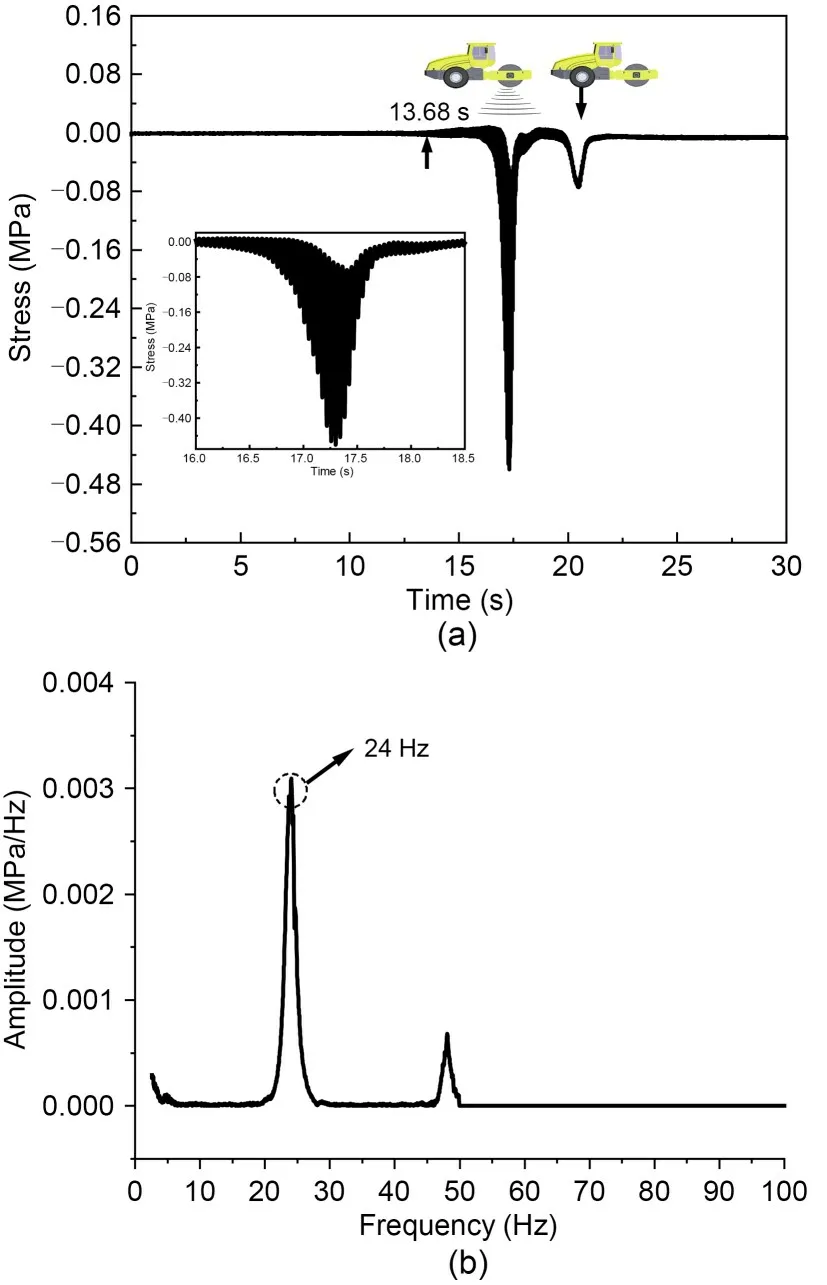
Fig.4 Dynamic soil stress caused by moving roller:(a)time history curve;(b)frequency spectrum curve
Fig.5 presents the maximum dynamic soil stresses at different depths with the number of roller passes.For the test section TS-65 with thickness layer of 65 cm as shown in Fig.5a,the maximum dynamic soil stress at the depth of 15 cm increased from 0.50 MPa to 1.18 MPa,caused by the static compaction of 260 kN(by the XS263J Roller)and dynamic compac‐tion of 700 kN(by the YZ362 Roller at 24 Hz)in the first two passes,respectively.Then the maximum dy‐namic soil stress decreased to 0.91 MPa and 0.55 MPa as the exciting force reduced to 500 kN(by the YZ362 Roller at 21 Hz) and 260 kN (by the XS263J Roller),respectively.It is clearly indicated that increased drum weight and vibratory frequency resulted in larger dy‐namic soil stresses.Besides,the dynamic soil stresses were observed to increase by 8.54%and 4.47%for the second compaction at the exciting forces of 700 kN and 500 kN,respectively,indicating that soils under‐went densification to support more loads.Similar phenomena also appeared at other soil depths as well as in the test section TS-80 with a thickness layer of 80 cm as shown in Fig.5b.The maximum dynamic soil stresses at the depth of 18 cm were 0.46 MPa,1.19 MPa,and 0.89 MPa as the exciting forces varied from 260 kN to 700 kN and 500 kN consecutively.Increased roller passes led to the increments of dy‐namic soil stresses by 7.87% and 8.46% at the excit‐ing force levels of 700 kN and 500 kN,respectively.
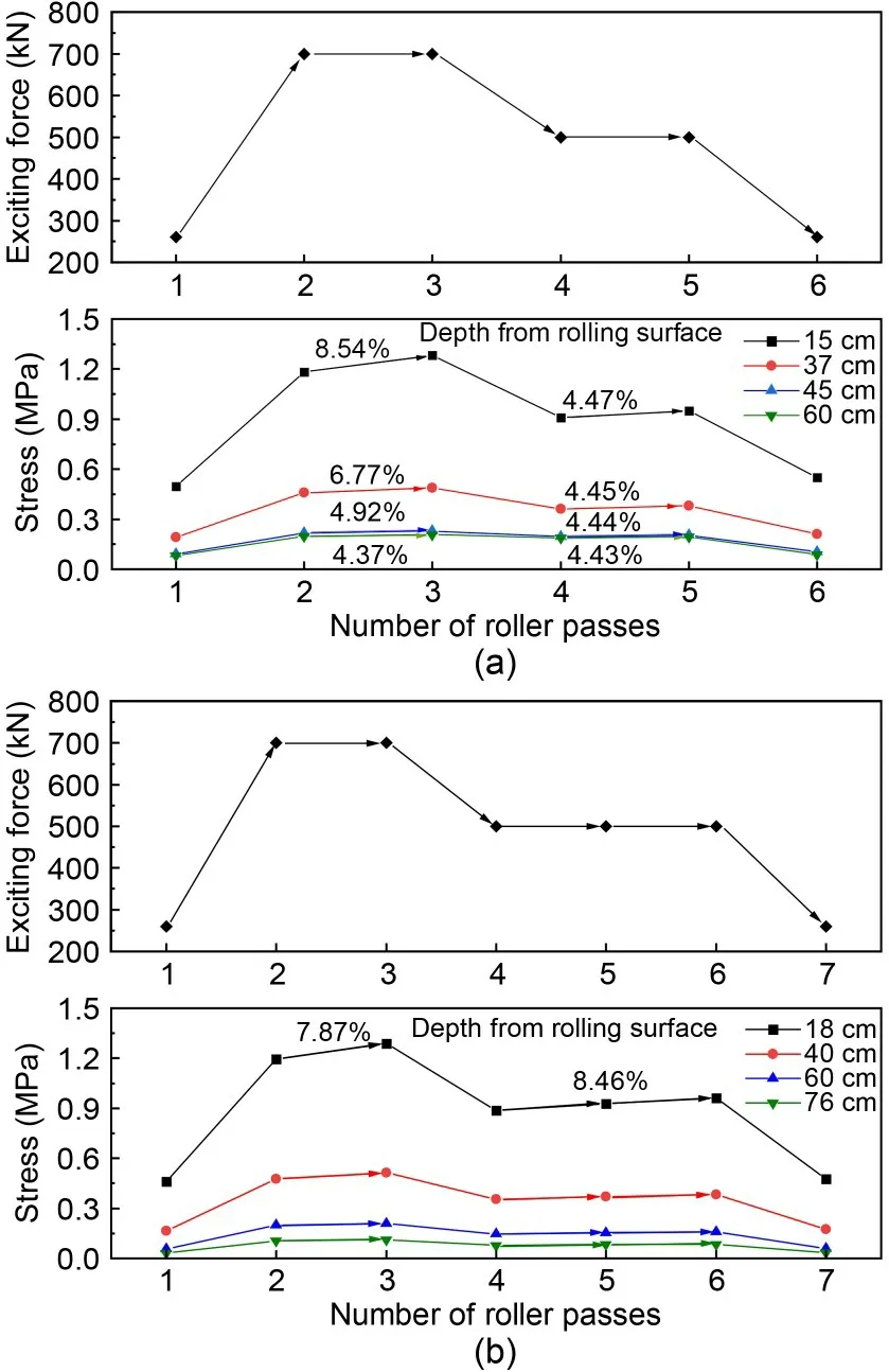
Fig.5 Maximum dynamic soil stresses under different exciting forces:(a)TS-65;(b)TS-80
To further investigate the influencing depths of roller compaction,Fig.6 presents the distributions of dynamic soil stresses along subgrade layers at differ‐ent exciting forces.It can be found that dynamic soil stresses caused by the heavy vibratory rollers were 2.4–5.9 times larger than those of traditional rollers of 260 kN,especially at greater depths.Dynamic soil stresses attenuated quickly in the upper depth of 0.4–0.45 m,and then decreased slowly along subgrade depths.Although dynamic soil stresses reduced to only 0.032–0.107 MPa at the bottom of the compaction layer,they always located above the line of selfweight stress as shown in Fig.6a,which helped to en‐sure that the energy propagated by the vibratory roller penetrated through the entire thickness layer.It has been stated that when dynamic soil stresses are lower than 20% of the subgrade self-weight stress,soils present almost elastic behavior and do not generate plastic deformation.On the contrary,subgrade soils could be densified in the full depth by all the three exciting forces.Meanwhile,dynamic soil stresses de‐creased from 0.50 MPa to 0.091 MPa within the depth of 0–0.45 m,with a reduction of almost 81.8%for the test section of TS-65.When the roller vibratory fre‐quency increased to 21 Hz and 24 Hz with exciting forces of 500 kN and 700 kN,dynamic soil stresses decreased from 0.91 MPa and 1.18 MPa to 0.19 MPa and 0.22 MPa with reductions of 79.1% and 81.4%,respectively.It is interesting to note that the attenua‐tion rates of dynamic soil stresses were approximately similar for different exciting forces.
Fig.6b shows the normalized stressσ/Pdecaying with subgrade depth (Pis the exciting force of the roller),which presents an independent relationship with the exciting forces.When the drum moves along the subgrade surface,the interface could be approxi‐mately assumed as a rectangular load with a length of 240 cm (l) and width of 15 cm (b).The Boussinesq model is used to describe the distribution of dynamic soil stress as shown in Eq.(4) and Fig.6b.Since the surface pressure by the drum is distributed nonuniformly and the limited compaction thickness does not satisfy the assumption of semi-infinite space,a dy‐namic stress attenuation coefficientkis introduced here to modify the Boussinesq equation to describe the dynamic soil stress caused by roller loading:wherezis the depth from the rolling surface,m=l/b,andn=z/b.The lower and upper boundaries of dy‐namic soil stresses are provided atk=1.073 and 1.169 based on the 95% confidence analysis as shown in Fig.6b,respectively.They show a good correlation with measured data.
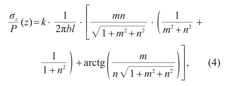
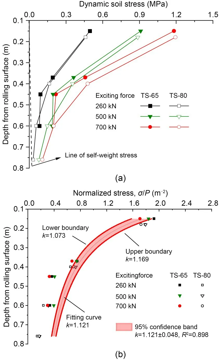
Fig.6 Distributions of dynamic soil stresses along subgrade layers: (a) absolute values of dynamic soil stress;(b)normalized soil stress
3.2 Compaction degree and settlement
Since the thickness layers of 65 cm and 80 cm were much larger than the traditional compaction layer,it is important to investigate the uniformity of compaction degree along the full subgrade depth.Based on the improved sand cone testing,Fig.7 illus‐trates the results of compaction degree at three dif‐ferent layers for both TS-65 and TS-80,i.e.,upper layer,middle layer,and bottom layer.Generally,soils were effectively compacted in a uniform fashion with respect to the full depth to 96.0%–97.2% and 94.1%–95.4% for the large-thickness layers of 65 cm and 80 cm within limited 6 or 7 passes,respectively.However,the compaction degree at different soil depths exhibited quite different development charac‐teristics with roller passes.For the test section of TS-65,it can be found that soils at the middle and bottom layers were densified quickly from initial values of 78.4%–78.5% to 93.0%–93.5% during the first three passes,especially under the exciting force of 700 kN.Then their compaction degree increased slowly to 96.0%–97.2% during the last three passes,where the compaction degree of the middle layer was 1.2%larg‐er than that of the bottom layer.Although the dynamic soil stresses at the upper layers were much larger than those at deeper depths,the growth of soil compaction degree at the upper layers lagged behind that at deeper subgrade depths which kept a linear increasing trend to 87.1% during the first three passes and then to 96.8% during the last three passes.It can be inferred that the dynamic stress level of 0.19 MPa at the bottom of thickness layer of 65 cm,caused by the ex‐citing force of 500 kN,had the ability to compact soils to the desired compaction degree up to 96.0%while,for the upper layers,rollers with 260 kN excit‐ing forces could compact soils to the desired compac‐tion degree.This was consistent with the results of the test section of TS-30 by the traditional rollers.More‐over,soils at upper layers were difficult to densify until the deeper layers had been rigidly compacted.This phenomenon is similar to the compaction of hot asphalt mixtures described by Yan et al.(2022).There‐fore,it is important to provide enough support from the bearing layer before carrying out subgrade compaction.
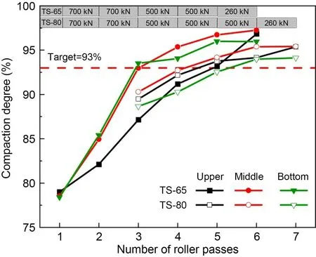
Fig.7 Compaction degree of each layer (upper,middle,bottom)with roller passes
In contrast,the growth characteristics of compac‐tion degree of three different depths were approxi‐mately synchronous for the test section of TS-80,where the values of compaction degree increased quickly to 88.6%–90.3% during the first three passes under an exciting force of 700 kN and then grew slowly to 94.1%–95.4% during the three passes of 500 kN and one pass of 260 kN.Although the dynamic soil stresses at the upper and middle layers were close for sections of TS-65 and TS-80,the stress value at the bottom of TS-80 was only 0.079 MPa,about half of that for TS-65,which led to a corresponding com‐paction degree 1.9% lower than that of TS-65.Such insufficient compaction at the bottom layer further re‐sulted in a relatively lower compaction degree at shal‐lower depths.If the thickness layer increased to greater than 80 cm,the full depth of subgrade might not be densified to the desired degree of compaction.
The elevation measuring points were arranged every 5 m×20 m spacing in the test sections.Fig.8 illustrates the accumulative settlement(S)and the rel‐ative difference (RD) of settlement between adjacent roller passes for test sections of TS-30,TS-65,and TS-80.The accumulative settlement presented an exponential growth trend and the final values were 51.92 mm,112.72 mm,and 129.4 mm after seven,six,and seven roller passes for those three test sections.Considering the initial thickness layers of 30 cm,65 cm,and 80 cm,the coefficients of loose paving were determined to be 1.21,1.21,and 1.19 in sequence.Larger coefficients represented better compaction quality for the same loose-paving subgrade.There‐fore,the compaction effects of TS-30 and TS-65 were slightly better than that of TS-80,which was consis‐tent with the results of compaction degree as shown in Fig.7.Meanwhile,the RD of settlement decreased gradually with the roller passes,which was always considered as an index for stopping rolling with a critical value of 5 mm.According to this criterion,the recommended roller passes seemed to be five,four,and five for the thickness layers of 30 cm,65 cm,and 80 cm,respectively.However,the actual proper roller passes should be five and six based on the results of compaction degree as shown in Fig.7.Therefore,for the subgrade filled with such GP,the critical value of RD should be adjusted to 4 mm to satisfy the soil compaction degree along the full subgrade depth.
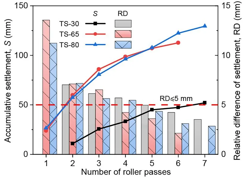
Fig.8 Accumulative settlement and relative difference of settlement
3.3 Bearing capacity of compacted subgrade
The subgrade reaction modulusK30is commonly used to evaluate the static bearing capacity of com‐pacted soils.Fig.9 plots the measured subgrade reac‐tion modulus with roller passes for two larger thick‐ness layers in comparison to the conventional thick‐ness of 30 cm.TheK30values increased approximately linearly with the roller passes,which reached about 188.2 MPa/m after six passes in TS-65 and 157.9 MPa/m after seven passes in TS-80.Since soils experienced better compaction in TS-65 than TS-80 as illustrated in Fig.7,they presented stronger static bearing capac‐ity in TS-65.As a contrast,theK30value of TS-30 was about 160.7 MPa/m after seven passes,which was similar to that of TS-80.It can be inferred that heavy roller compacted subgrade with large-thickness layers of 65 cm and 80 cm had equivalent or better static bearing capacity than that of conventional compaction thickness.Therefore,increasing thickness layer by heavy rollers is effective in replacing conventional technology in accelerating construction earthworks.
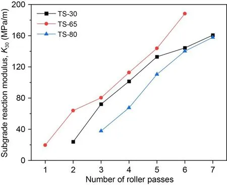
Fig.9 Subgrade reaction modulus(K30)
The dynamic modulus of deformationEvdis con‐sidered as an indicator for evaluating the dynamic bearing capacity of the subgrade.Fig.10 gives the measured dynamic modulus of deformation with roll‐er passes for the three thickness layers.TheEvdvalues also increased approximately linearly with the roller passes as that of theK30indicator,which finally reached about 62.8 MPa,57.7 MPa,and 67.3 MPa for TS-65 (six passes),TS-80 (seven passes),and TS-30(seven passes),respectively.In contrast to the sub‐grade reaction modulus as shown in Fig.9,the dy‐namic modulus of deformation of TS-65 was close to that of TS-30,both of which were larger than the value of the 80-cm-thick subgrade.The compacted subgrade actually exhibited the high dynamic bearing capaci‐ties at the criterion of 40 MPa as required for the sub‐grade in high-speed railways.
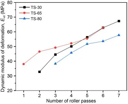
Fig.10 Dynamic modulus of deformation(Evd)
The dynamic deflectionLis the currently used acceptance indicator for a highway subgrade.Fig.11 presents the calculated dynamic deflection based on the FWD test,which decreased linearly to about 1.453 mm,1.561 mm,and 1.447 mm for TS-65,TS-80,and TS-30,respectively.According to the designed demand of 1.764 mm,the recommended roller passes would be five,six,and six for the thickness layers of 65 cm,80 cm,and 30 cm,respectively,and were in complete agreement with the results of compaction degree as shown in Fig.7.Therefore,the indicator of dynamic deflection is more reliable for evaluating the compaction quality for large-thickness layers than the indicators of subgrade reaction modulus and dynamic modulus of deformation.
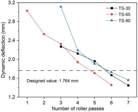
Fig.11 Dynamic deflection based on the FWD test
3.4 Relationships between compaction degree and testing indicators
Although the compaction degree is the design in‐dex for directly judging the compaction quality,it is quite time-consuming to measure it in the field,espe‐cially for the subgrade with large-thickness layers.Therefore,to establish the relationships between com‐paction degree and testing,indicators such as subgrade reaction modulusK30,dynamic modulus of deforma‐tionEvd,dynamic deflectionL,and relative difference of settlement RD,will be practical and convenient for the evaluation of roller compaction.Fig.12 plots the relationships between soil compaction degree and these testing indicators for thickness layers of 65 cm and 80 cm,which can be empirically expressed by the following linear formulae in Eqs.(5)–(12).

Fig.12 Relationships between compaction degree and indicators: (a) K30 versus compaction degree;(b) Evd versus compaction degree;(c) L versus compaction degree;(d) RD versus compaction degree
For thickness layer of 65 cm,

For thickness layer of 80 cm,

Therefore,according to the designed target of compaction degree at 93%,the corresponding crite‐ria ofK30,Evd,L,and RD are 107 MPa/m,51 MPa,1.97 mm,and 5.1 mm for the thickness layer of 65 cm,and 101 MPa/m,50 MPa,1.92 mm,and 3.8 mm for the thickness layer of 80 cm,respectively.If the de‐signed targets of compaction degree increase to 94%or 96%,the corresponding criteria could also be deter‐mined from the proposed empirical formulae.
4 Conclusions
1.The dynamic soil stresses in compacted layers could reach 0.19–1.18 MPa and 0.079–1.19 MPa for the thickness layers of 65 cm and 80 cm,respectively,which were large enough to densify the soils to the full depth.A unified empirical formula was proposed to determine the vertical distribution of dynamic soil stresses caused by roller excitation.
2.Soils of the full subgrade depth could be com‐pacted to 96.0%–97.2% and 94.1%–95.4% for the large-thickness layers of 65 cm and 80 cm,respec‐tively,which satisfied the designed target of 93%.Although the dynamic soil stresses at the upper layers were much larger than those at deeper depths,soils at the upper layers were difficult to densify until the deeper layers were rigidly compacted for the thickness layer of 65 cm.Therefore,it is important to provide enough support from the bearing layer to better den‐sify the upper subgrade.
3.Heavy roller compacted subgrade with largethickness layers of 65 cm and 80 cm had an even better bearing capacity than that of conventional compaction thickness.Therefore,increasing the thickness layer via heavy rollers is effective for replacing the conventional technology in accelerating earthworks construction.Moreover,the indicator of dynamic deflection is more reliable for evaluation of the compaction quality of large-thickness layers than the indicators of subgrade reaction modulus and dynamic modulus of deformation.
4.Compaction criteria ofK30,Evd,L,and RD were suggested for the designed targets of compac‐tion degree at 93% for the thickness layers of 65 cm and 80 cm.It can be concluded that increasing the thickness layer via heavy rollers would significantly reduce the cost and time burdens involved in construc‐tion while ensuring overall subgrade quality.These re‐lationships are beneficial to the quality control of in‐telligent compaction in future research.
Acknowledgments
This work is supported by the National Natural Science Foundation for Young Scientists of China (No.51608306),the Shandong Provincial Natural Science Foundation of China(Nos.ZR2021ME103 and ZR2021QE254),the Shandong Transportation Science and Technology Foundation (Nos.2020-MS1-044,2021B63,and 202060804178),and the Young Scholar Future Plan Funds of Shandong University,China.
Author contributions
Hong-guang JIANG designed the research.Xin-yu WANG,Yi-yi LIU,and Yan-kun GONG processed the corresponding data.Shu-jian WANG,Yu-jie WANG,and Yi-xin LI wrote the first draft of the manuscript.Kai WANG helped to organize the manuscript.Zong-bao WANG and Xue-yu GENG revised and edited the final version.
Conflict of interest
Shu-jian WANG,Hong-guang JIANG,Zong-bao WANG,Yu-jie WANG,Yi-xin LI,Xue-yu GENG,Xin-yu WANG,Kai WANG,Yi-yi LIU,and Yan-kun GONG declare that they have no conflict of interest.
 Journal of Zhejiang University-Science A(Applied Physics & Engineering)2022年11期
- Journal of Zhejiang University-Science A(Applied Physics & Engineering)的其它文章
- Visualizing the dynamic progression of backward erosion piping in a Hele-Shaw cell
- Frozen sand–concrete interface direct shear behavior under constant normal load and constant normal height boundary
- Shaking table tests on a cantilever retaining wall with reinforced and unreinforced backfill
- Model test of the mechanism underpinning water-and-mud inrush disasters during tunnel excavation in sandstone and slate interbedded Presinian strata
- Soil effect on the bearing capacity of a double-lining structure under internal water pressure
- Influence of groundwater level changes on the seismic response of geosynthetic-reinforced soil retaining walls
