
Dynamic Power Transmission Using Common RF Feeder with Dual Supply
2022-07-18 14:12:54DUONGQuangThangVOQuocTrinhPHANThuyPhuongOKADAMinoru
ZTE Communications 2022年2期
DUONG Quang?Thang ,VO Quoc?Trinh ,PHAN Thuy?Phuong ,OKADA Minoru
(1.Nara Institute of Science and Technology,Nara 630-0192,Japan;2.FPT University Da Nang,Da Nang 50500,Vietnam)
Abstract: This paper proposes the design concept of a dynamic charging system for electric vehicles using multiple transmitter coils connected to a common radio frequency (RF) feeder driven by a pair of two power supplies.Using a common RF feeder for multiple transmitter coils reduces the power electronic redundancy compared to a conventional system,where each transmitter coil is individually driven by one switched-mode power supply.Currently,wireless charging of electric vehicles is recommended to operate in the frequency range of 85 kHz and beyond.In this frequency range,the signal wavelength is shorter than about 3.5 km.Therefore,a charging pad longer than several hundred meters is subject to the standing wave effect.In such a case,the voltage significantly varies along the RF feeder,resulting in a variation in the received power level when the receiver moves.Specifically,the received power significantly deteriorates when the receiver is nearby a node of the voltage standing wave.In this paper,we employ a pair of two power sources which are electrically separated by an odd-integer number of the quarter wavelength to drive the RF feeder.As a result,the voltage standing wave generated by one power source is complemented by that of the other,leading to stable received power and transmission efficiency at all the receiver’s positions along with the charging pad.Simulation results at the 85 kHz frequency band verify the output power stabilization effect of the proposed design.It is worth noting that the proposed concept can also be applied to simultaneous wireless information and power transfer (SWIPT)for passive radio frequency identification(RFID)tags by raising the operation frequency to higher industrial,scientific and medical (ISM)bands,e.g.,13.56 MHz and employing similar modulation methods as in the current RFID technology.
Keywords: dynamic charging;common RF feeder;standing wave;dual power supply
1 Introduction
Dynamic charging for moving electric vehicles (EVs) is considered a complement to the capacity limitation of battery technology[1–5]in increasing the driving range,reducing the battery size and the manufacturing cost.Currently,dynamic charging is being developed based on magnetic induction[6],where an AC-driven transmitter coil buried under the road wirelessly induces an electric current in the receiver coil usually placed under the chassis of EVs.The wireless energy transmission principle is simple.However,designing an effective and practical dynamic charging system is very challenging because of the large scale of infrastructure,the high charging power level,the strict requirements on safety for human bodies and devices nearby,and the requirements on cost and efficiency.
Several dynamic charging systems have been proposed so far.Considering the ground infrastructure,the current dynamic charging techniques can be classified into two basic designs:the multi-coil design[7–8]and long-track design[9–10].As illustrated in Fig.1(a),in the multiple-coil design,many transmitter coils are installed under and along the road to provide a wide charging range for the EV while it is on the move.Meanwhile,in the long-track design in Fig.1(b),the wide charging range is provided by only one elongated transmitter coil.In terms of structure,the multiple-coil design is more complex compared to the long-track design.However,by sensing the EV position,the multiple-coil design can turn on only the transmitter coil right under the EV to focus the magnetic energy,prevent a leaked electromagnetic (EM) field to surrounding space,and achieve high power transfer efficiency.On the contrary,the long-track design suffers from low efficiency and a large leaked EM field because it generates the EM field across the whole charging range.For that reason,the multiplecoil design is a preferable option if its structure is simplified by some means.
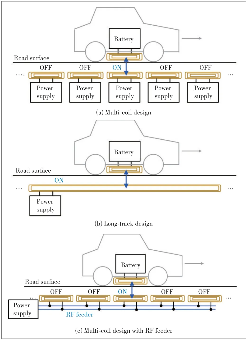
▲Figure 1. Dynamic charging systems for electric vehicles(EVs)
The complexity of the multiple-coil design in Fig.1(a)comes from the fact that many coils need to be installed and,more importantly,the huge power electronic burden required to drive the coils.Conventionally,each transmitter coil is equipped with a switched-mode power supply to convert 50 Hz/60 Hz AC into a radio frequency (RF) signal for efficient wireless energy transmission.For instance,in order to carry out dynamic charging on a 100 m road by using transmitter coils with the size of 1 m×1 m,one hundred power supplies of output from several kW to several tens of kW are required.The number of power sources increases when further extending the charging range.In fact,the conventional driving mechanism is redundant because at any time instant there is only one power source in operation while the others are in the waiting state.To reduce such a power electronic redundancy,an RF feeder line should be used to carry signals from one central power source to the coils as illustrated in Fig.1(c).In such a system,by controlling the switches that connect the feeder to the coils,the automatic coil activation/deactivation effect in the conventional multiple-coil design can be realized.Also,the multiple-coil design with a common RF feeder is flexible in satisfying the required power level in practical applications.Power supply with high output may be used when the system is deployed in roads with many EVs.Lower output sources may be used in not-crowded road deployment.
The multiple-coil structure with a common RF feeder is a promising design for dynamic charging.However,this design suffers from a standing wave problem when extending the charging range.Currently,the 85 kHz frequency range is recommended for wireless charging of EVs.In this frequency range,the signal wavelength is about 3.5 km.Therefore,if the RF feeder length is about several hundreds of meters or more,the signal strength variation along the feeder becomes significant.In the extreme,if the feeder length is longer than a quarter wavelength of about 882 m,there will be nodes and antinodes in the voltage standing wave[11]pattern along the feeder.In such a case,the EV receives high power if it nears an antinode but receives very low power if it nears a node.In order to deal with this problem,we propose a multiple-coil charging system using a common RF feeder driven by a pair of two power supplies located at its two ends.In our design,the two power sources are electrically separated by an odd-integer number of the quarter wavelength.Thus,voltage standing waves generated by the two power supplies will compensate for each other in stabilizing the received power for the EV.
It is worth noting that the proposed concept can be applied to short-range wide-coverage simultaneous wireless information and power transfer (SWIPT) for passive radio frequency identification (RFID) tags.This application can be realized by raising the operating frequency to an industrial,scientific and medical (ISM) band in the MHz range,e.g.,6.78 MHz or 13.56 MHz,and reducing the dimensions of each coil to several centimeters.The power transmission has the same principle as that in the dynamic charging mechanism mentioned above;the information transmission methods are similar to those in current RFID technology.For instance,communications from the power transmitter (transponder) to the power receiver (tag) can use amplitude modulation,and communications in the reverse direction can employ load modulation.
In this paper,for simplicity,we focus on the dynamic charging application for EVs using the operating frequency of 85 kHz.Following theoretical analysis,system-level simulations using LTspice will be provided to confirm the receive power stabilization effects of the proposed concept.
2 Design Concept of Proposed Dynamic Charging System
We consider a dynamic charging system for EVs as described in Fig.2.For simplicity,let us assume that the charging pad is serving one receiver (EV)at a time.Similar to many conventional dynamic charging systems,the proposed system consists of many transmitter coils buried under the road to deliver power to the receiver moving from the left to the right in the figure.The difference in our design is that all the transmitter coils and their associated compensation circuits are connected to a common RF feeder.In doing so,our system significantly reduces power electronic redundancy compared to the conventional system using one power supply for one transmitter coil.The RF feeder is a transmission line of any configuration,but preferably the one with low loss and ease of installment.In this paper,to avoid detailed discussion on the feeder,let us assume that the feeder is a lossless transmission line having real-valued characteristic impedanceZ0.
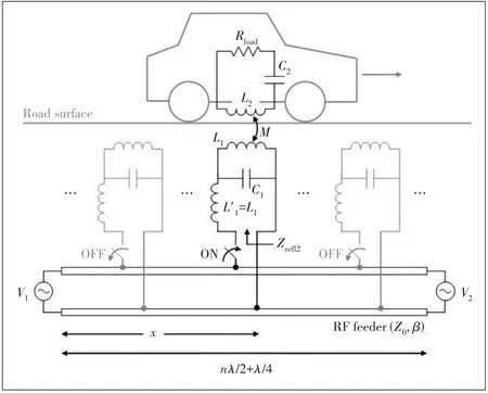
▲Figure 2. Proposed dynamic charging system
The common RF is driven by a pair of two power sources which are designed to operate within a certain frequency bandf,with the angular frequencyω=2πf.Here,it is worth noting that our system does not require perfect frequency and time synchronizations between the two power supplies.The two source frequencies may be respectively slightly shifted from each other.The frequency shifts should be random so that the two sources do not interfere with each other,but these shifts should be small enough so that the system can be considered to resonate atf.These requirements are easily satisfied because the actual frequencies of power supplies are always different from their designed value.There are no need for frequency and phase control between the sources.
Given the operation frequency rangef,the electrical length of the RF feeder should be an odd-integer number of the quarter wavelength

whereλ=c/fis the wavelength andnis an integer.This does not mean that the proposed system is effective only when the length of the charging pad takes one of these special values.If the charging pad has the lengthLpthat is different fromLe,a circuit equivalent to a transmission line portion having characteristic impedanceZ0and length (Le-Lp) can be inserted into the feeder for compensation.Here,for the sake of simplicity let us assume that the actual length of the charging pad is also equal toLegiven by Eq.(1).Under this condition,the following effects are expected:
? The RF feeder is seen as a quarter wavelength resonator at the frequencyf,which enables efficient power transmission from the sources to the transmitter coils.
? The voltage standing wave patterns generated by the two sources compensate for each other.At positions where the voltage generated by the first source is small,the voltage generated by the second is large,and vice versa.This effect guarantees a stable received power for the EV when it moves along the charging pad.
? The condition of the feeder length also separates the two sources from each other.The internal resistance of one source is seen as a very large impedance by the other.This effect prevents energy transfer between the sources.
Without loss of generality,let us assume that all the transmitter coils have identical inductances denoted byL1as shown in Fig.2.The inductance of the receiver coil is denoted byL2and the mutual inductance between the receiver and each of the transmitter coils isM.The strength of coupling betweenL1andL2is represented by a coupling coefficientk=which takes value from 0 to 1.The larger the value ofk,the stronger the coupling.As for wireless charging of EVs,the coupling coefficient usually takes a value of around 0.1,or at most around 0.2.
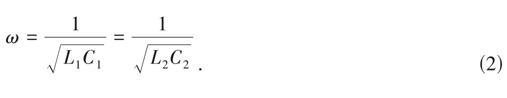
The load resistance is denoted byRload.The system is assumed to be equipped with a mechanism that can automatically turn on only the transmitter coil right below the EV and turn off the others to prevent losses and leaked EM fields to the surrounding space.The receiver coilL2is resonated in series with a capacitorC2while each transmitter coil is compensated by an inductor-capacitor-inductor (LCL) circuit[12–13].The LCL circuit helps to create a largely reflected impedance of the load on the RF feeder,therefore the voltage standing wave patterns will not change so much while the EV is moving.As the standing wave patterns compensate each other,the received power is expected to be stable against the EV movement.This effect will be explained in Section 3.Another effect of the LCL circuits is that they keep the currents in the coils small when not coupled with the load.This effect provides the second protection for the transmitter coils in addition to the automatic turn-on/turn-off mechanism.The resonance condition of the compensation circuits is given by
3 Principle of Output Power Stabilization
In Fig.2,voltages of the power sources are denoted byV1andV2,respectively.Distance from the first source to the receiver position is denoted byx.The phase constant of the RF feeder is denoted byβ.As mentioned above,the RF feeder is assumed to be a lossless transmission line with a real-valued characteristic impedanceZ0.The phase constant therefore can be calculated asβ=2π/λ.
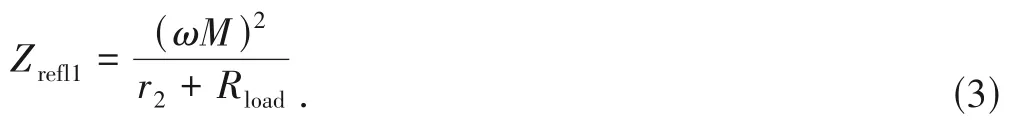
When the RF feeder is lossless and the internal resistances of the sources are negligibly small,the power transfer efficiency of the whole system is dominated by the coupling link between the receiver coil and each transmitter coil.Via the mutual couplingM,the load resistanceRloadand the receiver resistancer2reflect an impedanceZrefl1onto the transmitter coilL1.
Consequently,via the LCL circuit on the transmitter coil,the impedanceZrefl1and the transmitter resistancer1reflect another impedanceZrefl2onto the RF feeder at positionx.
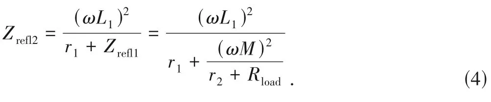
Often,wireless charging coils are designed so that their internal resistances are small.Therefore,the reflected impedanceZrefl2can be approximated as
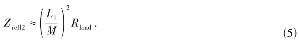
This meansZrefl2is approximately a multiplication of load resistanceRloadby (L1/M)2times.Also,as the inductancesL1andL2take similar values,the ratioL1/Mis approximately equal to 1/k,which may take values around 10.As a result,the reflected impedanceZrefl2is a multiplication ofRloadby about 100 times.IfRload=5 Ω,Zrefl2≈500 Ω;ifRload=10 Ω,Zrefl2≈1 000 Ω,and so on.Thus,due to the effect of the LCL circuit,the reflected impedanceZrefl2usually takes quite a large value.This effect is needed to conserve the voltage standing waves,which are designed to compensate each other to stabilize the output power for the load.
When ignoring losses in the RF feeder and the internal resistances of the power sources,losses arise mainly in the transmission from each transmitter coil to the receiver coil.Power transfer efficiency from the transmitter coilL1to the loadRloadvia the mutual inductanceMis given by
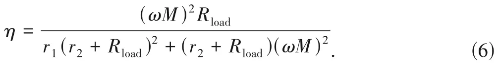
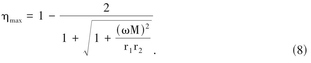
As shown in Eq.(6),the power transfer efficiency from the transmitter coil to the receiver coil depends on the load resistance.The efficiency takes its maximum value when the load resistance is given by
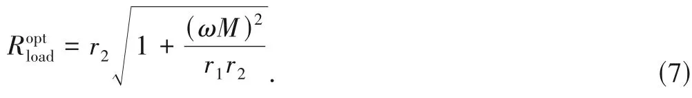
The maximum value ofηassociated with the load resistanceis
The proposed system can be simplified as shown in Fig.3,where the coupling link between the transmitter coil and the receiver coils is represented by the reflected impedanceZrefl2placed on the RF feeder at positionx.The output powerPoutat the load can be expressed as

wherePin1andPin2are respectively the input power by the first and the second sources.
Now,let us consider the input power by the sources.Because the two power sources operate at slightly different frequencies aroundω,their signals do not interfere with each other.Therefore,we can separately consider the power transmissions from each source to the load via the common RF feeder.In doing so,the common RF feeder can be considered in two parts:the first part isx[m] long from the first source to the receiver position,and the second part is[(2k+1)λ/4 -x] [m] long from the receiver position to the second source.Looking from the first source,the second part is approximately terminated in a short circuit.Based on the transmission line theory[11],the input impedance of the second part can be expressed as

This impedance is connected in parallel with the reflected impedanceZrefl2of the load,resulting in a composite impedanceZLexpressed by
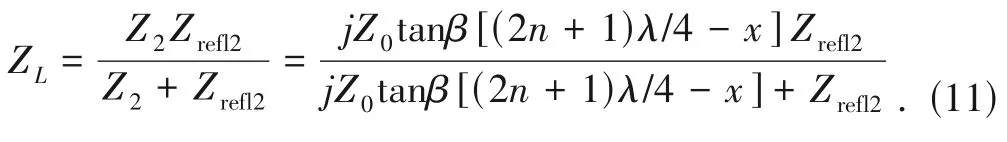
This impedance becomes the terminating impedance for the first part of the feeder.As a result,the input of the whole feeder seen from the first power source is
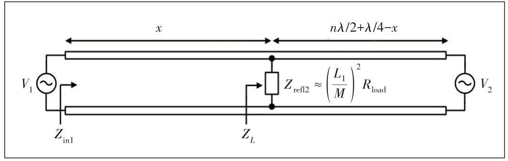
▲Figure 3. Simplified circuit of proposed system
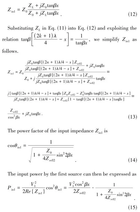
Formulation of power transmission from the second source can be carried out in a similar manner to that for the first power source.Looking from the second source,the first part of the RF feeder is approximately terminated in a short circuit.The first part and the reflected impedance are connected in parallel and form a composite impedance that terminates the second part of the feeder.In the transmission from the second source,the two parts of the RF feeder reverse their positions as in the transmission from the first.Therefore,the input impedance of the loaded feeder seen from the second sourceZin2can be straightforwardly obtained from Eq.(13) by replacing the length of the first part,x,with that of the second,(2n+1)λ/4 -x,and vice versa.
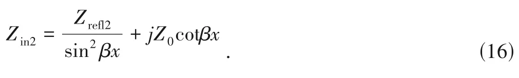
The power factor of the input impedanceZin2is
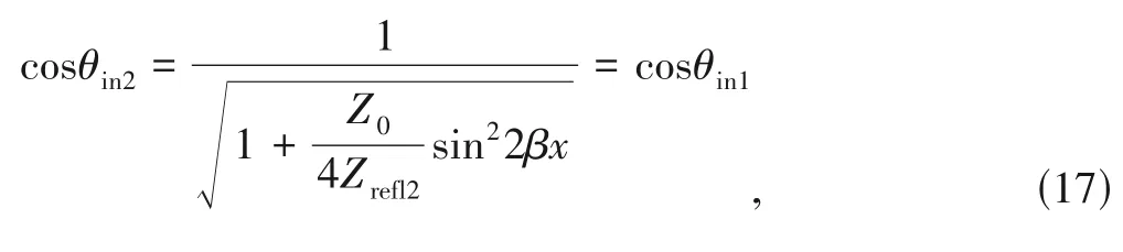
which is identical to that of the input impedanceZin1.The input power by the second source can then be expressed as
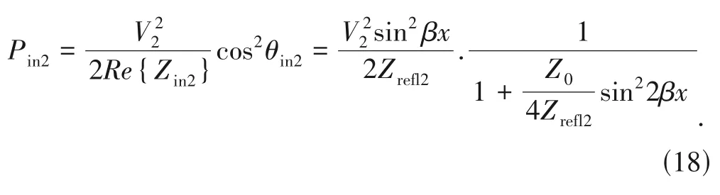
Eventually,the received power at the load can be expressed as
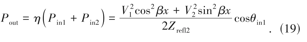
In the proposed system,the reflected impedanceZrefl2is sufficiently large.In such a case,the power factors are approximately cosθin1=cosθin2≈1.As a result,the input powerPin1andPin2can be approximated as
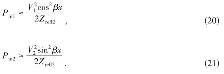
Eqs.(20) and (21) show that when the receiver moves along the road,the input powerPin1andPin2exhibit two standing wave patterns shifted by a quarter wavelength.When the receiver is near the positionx=nλ/2,it draws more power from the first source and less power from the second.Reversely,when the receiver is near the positionx=λ/4 +nλ/2,it draws more power from the second source and less power from the first.In this way,the two power sources compensate each other in stabilizing output power for the load.Furthermore,the source voltages should be set identically asV1=V2=V0,so that the output power can be approximated as
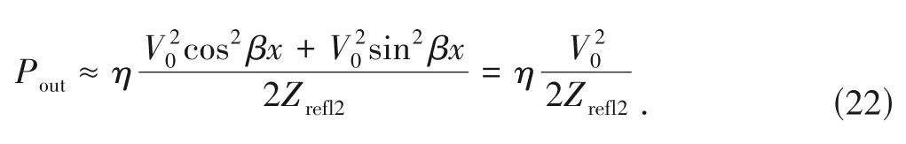
As a result,the total power that the receiver receives will be stabilized for all positions of the receiver along the RF feeder.
4 Computer Simulation Results
This section provides computer simulations to confirm the output power stabilization effect of the proposed system.We use LTspice software to emulate the system configuration described in Fig.2.In the simulations,the system is designed to operate at the frequencyf=85 kHz.The two power sources are set to operate at the frequencies of 85 kHz and 85.5 kHz,respectively.Here,the frequency shift Δf=0.5 kHz is not that important.It can be any value as long as it guarantees that the two power sources operate independently in the resonant frequency band of the system.Also,the phase shift between the two sources is chosen randomly.The source voltages are identicallyV1=V2=2 kV,and their internal resistances are set identically to 1 Ω.
The RF feeder is assumed to be a two-wire transmission line consisting of two parallel conductors with a diameter of 10 mm.The center-to-center distance between the two conductors of the RF feeder is 21.8 mm,corresponding to the characteristic impedanceZ0≈120 cosh-1=170 Ω.The parameters of the coils,resonant capacitors and the coupling coefficient are listed in Table 1.The simulation circuit configuration is illustrated in Fig.4.The mutual coupling coefficient between the transmitting coil and receiving coil is set to be 0.1 or 0.2.A lossless transmission line model is used to emulate the RF feeder.The RF feeder length is 882 m (a quarter wavelength)or 2 646 m(three quarter wavelengths).The power supplied by AC sources and received by the receiver is calculated over the steady-state period of 2 ms (from 10 ms to 12 ms)which is as sufficiently long as about 170 times the period of the operating frequency 85 kHz.The duration of 2 ms is also equal to one period 1/Δfof the frequency shift to make the average power calculations accurate.This can be confirmed by Fig.5 which shows snapshots of waveforms forx=10 m.
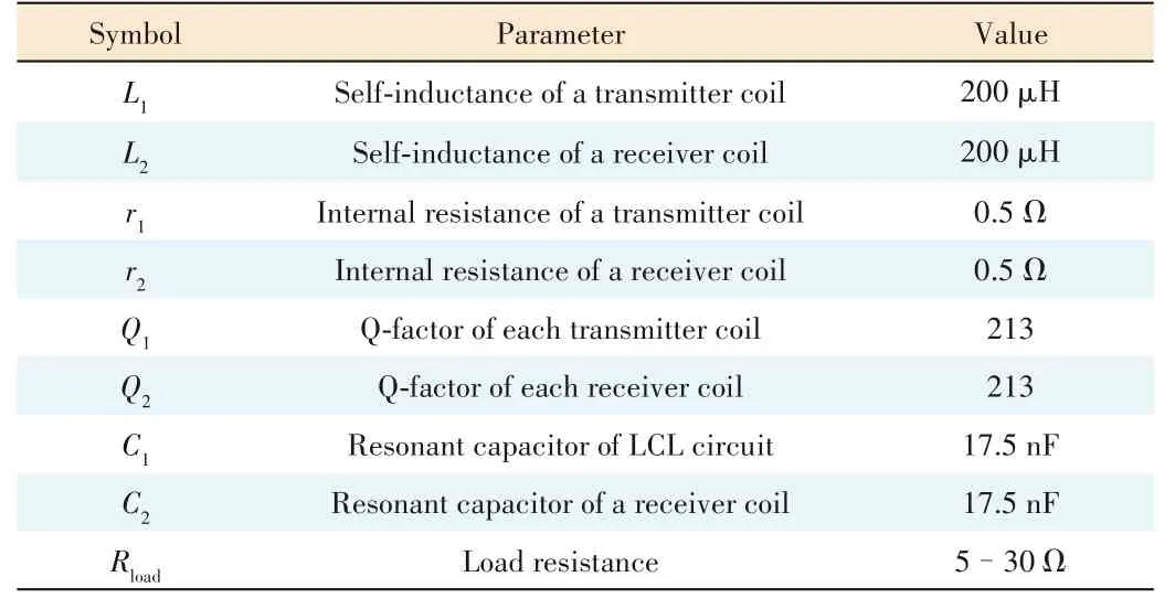
▼Table 1. Simulation parameters for circuit in Fig.4
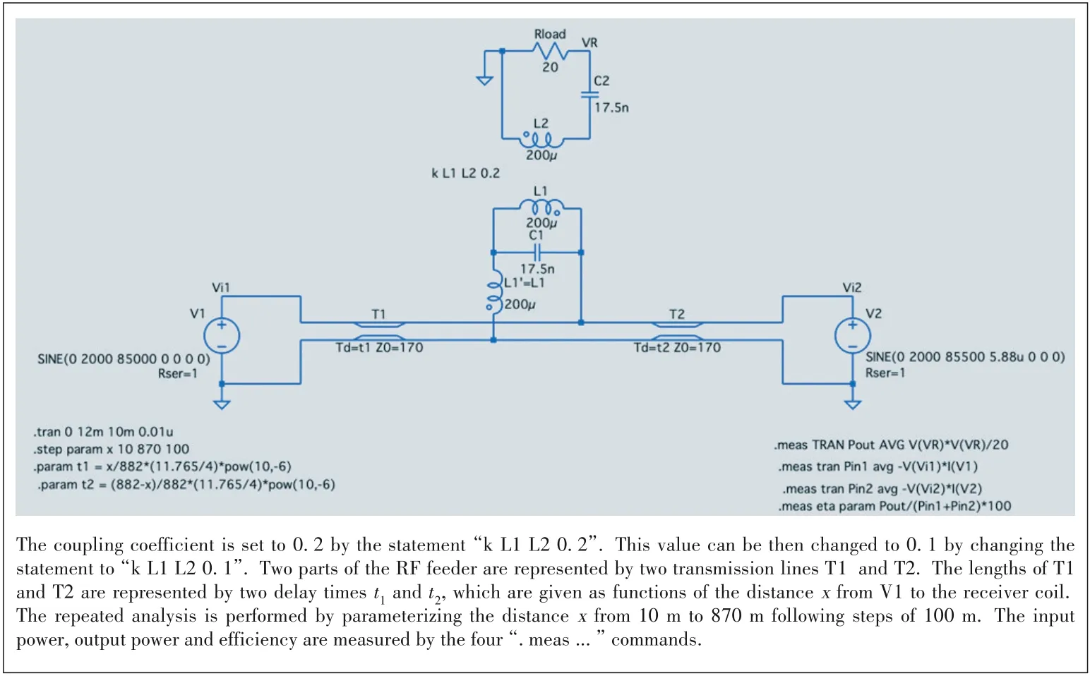
▲Figure 4. A snapshot of computer simulations with LTspice
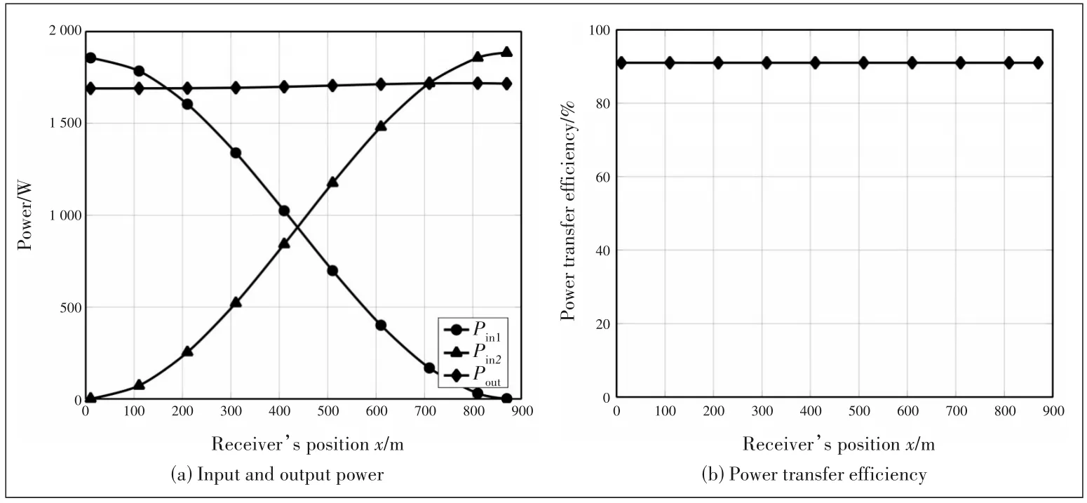
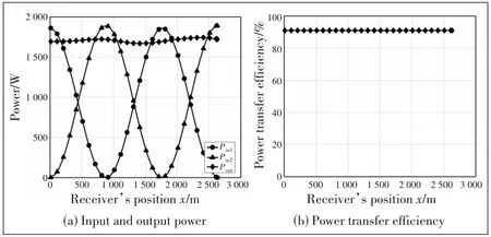
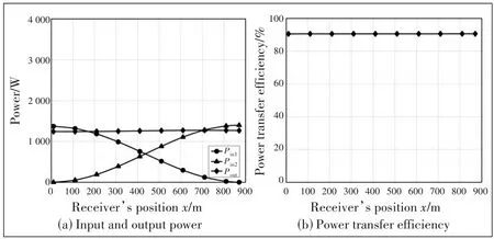
Fig.6(a) plots the input power from each power source and the out power received at the load when the receiver moves along the RF feeder.Here,the feeder length is a quarter wavelength.The coupling coefficient between each transmitter and the receiver isk=0.1.According to this value ofk,the optimal load resistanceRload=10.7 Ω is chosen to achieve the theoretical maximum efficiencyηmax=91%following Eqs.(7)and (8).In this case,the reflected impedance of the load onto the RF feeder is estimated asZrefl2=1 073 Ω which is sufficiently larger (about 6.3 times) compared to the characteristic impedance 170 Ω of the feeder.This setting satisfies the conditions for achieving stable output power,which is mentioned in our theoretical analysis in Section 3.As shown in Fig.6(a),the input power from the first sourcePin1gradually decreases from 1.8 kW to nearly 0 kW when the receiver moves from the positionx=0 m to the positionx=882 m=λ/4.This variation ofPin1withxalmost follows the cos2βxfunction shown in Eq.(20).Reversely,the input power from the second sourcePin2gradually increases from 0 kW to nearly 1.8 kW for the same movement of the receiver,which almost follows the sin2βxfunction shown in Eq.(21).More importantly,the output powerPoutat the load is stable at around 1.7 kW regardless of the position of the receiver.As a result,as can be seen from Fig.6(b),the power transfer efficiency is stable at 91%,which agrees with the calculation following Eq.(8).Fig.7 confirms similar characteristics of the input power,output power and efficiency for the case where the feeder length is three quarter wavelengths.All of these results agree with our theoretical analysis in Section 3.
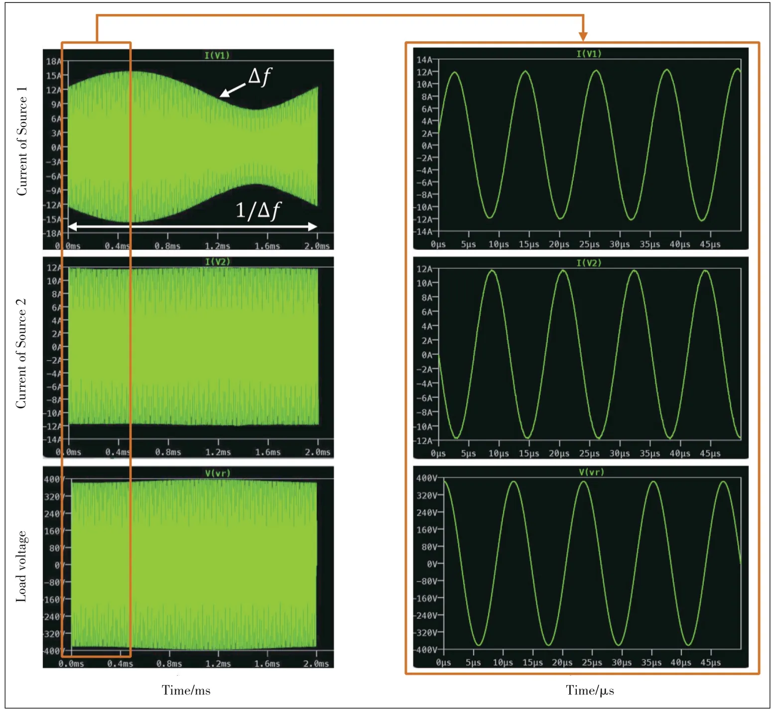
▲Figure 5. Snapshots of waveforms for x=10 m indicating that the analysis is in steady-state
▲Figure 6. Simulation results for k=0.1,Rload=10.7 Ω(optimal load),and Le=λ/4
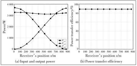
Fig.8 demonstrates the results for the casek=0.1,Rload=5 Ω,andLe=λ/4.In this case,the input power still follows the theoretical analysis in Eqs.(20)and (21),the power transfer efficiency is stable but the output power slightly varies when the receiver is moving.This is because the reflected impedance of the load becomesZrefl2=500 Ω,which is nearly 3 times the characteristic impedance of the feeder.As the reflected impedanceZrefl2is not sufficiently large,the receiver movement affects the voltage standing wave patterns and deteriorates their mutual compensation.As can be seen from Fig.8(a),the total power of about 3.7 kW has been input from the sources.This power level is larger than that in Fig.5.This is because whenZrefl2decreases,the input power increases as shown in Eqs.(20)–(22).Fig.9 demonstrates the results for the casek=0.1 andRload=15 Ω.In this case,the power transfer efficiency and the output power are stable;the input power level decreases to about 1.4 kW.This is becauseZrefl2has increased to 1 500 Ω,which is nearly 9 timesZ0.
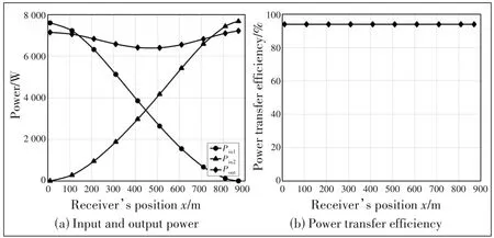
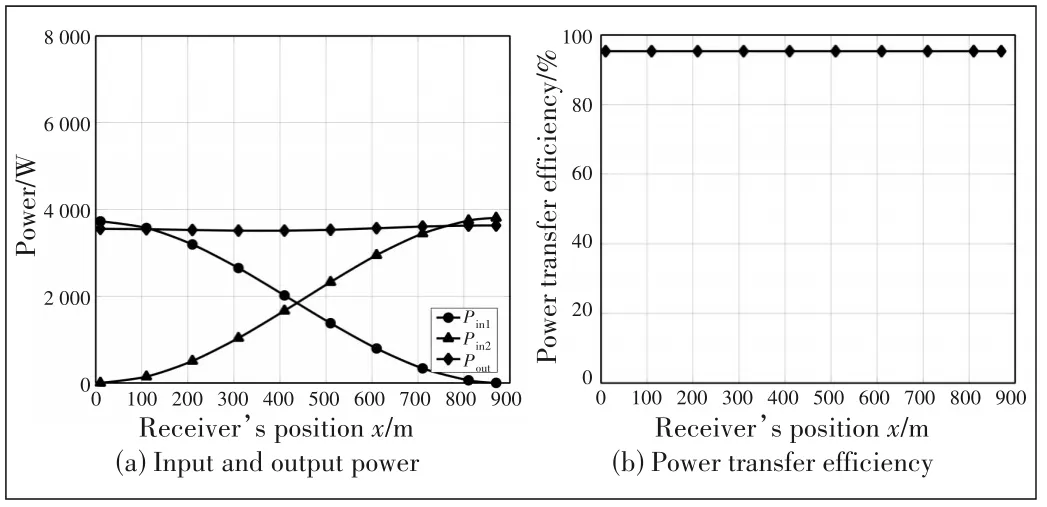
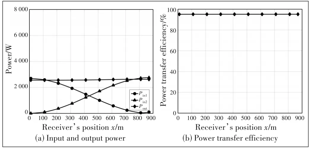
Figs.10–12 demonstrate the simulation results for the case of stronger coupling withk=0.2 and load resistance of 10 Ω,21.3 Ω(optimal load) and 30 Ω,respectively.Fig.10(a) exhibits a small fluctuation in the output power because in this case the reflected impedanceZrefl2=(1/0.2)2×10=250 Ω,which is not sufficiently larger (only nearly 1.5 times)compared to the characteristic impedanceZ0=170 Ω.Meanwhile,Figs.11(a) and 12(a)show stable output power because in these cases,the reflected impedance becomes 532.5 Ω and 750 Ω,which are quite larger (3.1 times and 4.4 times,respectively) compared toZ0.The power transfer efficiency is observed as 94%,95.3% and 95%,respectively for each value of the load resistance.The efficiencies increase compared to the results in Figs.6–8 because the coupling coefficient is doubled.The input power level also increases to 7.6 kW,3.7 kW and 2.7 kW,respectively for each value of the loads.The reason for the increase in input power level is that the reflected impedance has decreased.
5 Conclusions
In this paper,we have proposed the design concept of a dynamic charging system for the EV using multiple transmitter coils connected to a common RF feeder driven by a pair of two power supplies.The computer simulations at the 85 kHz band confirm that the voltage standing waves generated by a pair of two sources mutually compensate each other and deliver stable output power regardless of the receiver position along the road.In summary,the advantages of our proposed system are as follows.
▲Figure 7. Simulation results for k=0.1,Rload=10.7 Ω(optimal load),and Le=3λ/4
▲Figure 8. Simulation results for k=0.1,Rload=5 Ω,and Le=λ/4
▲Figure 9. Simulation results for k=0.1,Rload=15 Ω,and Le=λ/4
▲Figure 10. Simulation results for k=0.2,Rload=10 Ω,and Le=λ/4
?The proposed charging pad can obtain attractive effects as in any multi-coil charging system,activating only the transmitter coil right under the receiver,focusing the magnetic energy toward the receiver,achieving effective power transmission,and reducing EM leakage to surrounding space.
▲Figure 11. Simulation results for k=0.2,Rload=21.3 Ω(optimal load),and Le=λ/4
▲Figure 12. Simulation results for k=0.2,Rload=30 Ω,and Le=λ/4
? Using a common RF feeder for all transmitter coils,our system reduces the power electronic redundancy compared to conventional multiple coil systems,where each transmitter coil is individually driven by one switched-mode power supply.
? Our system can deliver stable output power and achieve stable power transfer efficiency regardless of the receiver position along with the charging pad.
? The proposed system can be easily applied in practice.Although the electrical length of the RF feeder is required to be an odd-integer number of the quarter wavelength,the length of the proposed charging pad can be flexibly chosen according to the practical applications as long as the copper loss is small enough.The difference in the actual length and the required electrical length can be resolved by inserting a compensation circuit into the feeder.Also,the proposed system does not require any time and frequency synchronization between the two sources as long as they operate at slightly different frequencies within the resonant point around the target frequency band.The requirement that the reflected impedance of the load onto the feeder should be large is not so strict and can be satisfied easily.As can be seen from the simulation results in Section 4,a reflected impedance of about 1.4 times the characteristic impedance is enough for a quite stable output power profile.
? The proposed concept can also be applied to SWIPT for passive RFID tags by raising the operating frequency to an ISM MHz band and employing similar modulation methods as in the current RFID technology.
- ZTE Communications的其它文章
- Programmable Metasurface for Simultaneously Wireless Information and Power Transfer System
- A Radio?Frequency Loop Resonator for Short?Range Wireless Power Transmission
- Polarization Reconfigurable Patch Antenna for Wireless Power Transfer Related Applications
- Optimal Design of Wireless Power Transmission Systems Using Antenna Arrays
- Editorial:Special Topic on Simultaneous Wireless Information and Power Transfer:Technology and Practice
- An Overview of SWIPT Circuits and Systems