Analysis of electromagnetic pulses generated from ultrashort laser irradiation of solid targets at CLAPA
Yi-Lin Xu(徐毅麟) Dong-Yu Li(李東彧) Ya-Dong Xia(夏亞東) Si-Yuan Zhang(張思源) Min-Jian Wu(吳旻劍)Tong Yang(楊童) Jun-Gao Zhu(朱軍高) Hao Cheng(程浩) Chuan-Ke Wang(王傳珂)Chen Lin(林晨) Ting-Shuai Li(李廷帥) and Xue-Qing Yan(顏學(xué)慶)
1School of Materials and Energy,University of Electronic Science and Technology of China,Chengdu 611731,China2State Key Laboratory of Nuclear Physics and Technology,and Key Laboratory of HEDP of the Ministry of Education,CAPT,Peking University,Beijing 100871,China3Research Center of Laser Fusion,China Academy of Engineering Physics(CAEP),Mianyang 621900,China
Electromagnetic pulses(EMPs)produced by the interaction of a TW femtosecond laser with solid targets at the Compact Laser Plasma Accelerator(CLAPA)are measured and interpreted. The statistical results confirm that the intensities of the EMPs are closely related to both target material and thickness. The signal of the titanium target is more abundant than that of the copper target with the same thickness,and the intensity of EMP is positively correlated with the target thickness for aluminium foil. With the boosted EMP radiations,the energy of accelerated protons is also simultaneously enhanced.In addition,EMPs emitted from the front of the target exceed those from the rear,which are also pertinent to the specific target position. The resonant waveforms in the target chamber are analyzed using the fast Fourier transform, and the local resonance and the attenuation lead to changes of the frequency spectra of EMPs with variation of detecting positions,which is well supported by the modeling results. The findings are beneficial to gaining insight into the mechanism of EMP propagation in a typical target chamber and providing more information for EMP shielding design.
Keywords: laser driven proton accleration,electromagnetic pulses,laser,target
1. Introduction
Ultrashort and intense laser irradiation of solid targets leads to emissions of energetic particles,which is also accompanied by a large amount of broadband electromagnetic pulse(EMP)radiation.[1,2]In recent years,with the increase of laser intensity, EMPs have been paid more and more attention due to their close relationship with hot electrons and the target current,which also cause electromagnetic interference with various diagnosing devices and result in malfunction of some crucial equipment.[3]Previous studies confirm that laser irradiation results in the ejection of numerous hot electrons,which further bring about the return current through the target holder,compensating for the deficit of negative charge. Hot electrons and the target current are the two distinct sources of EMPs.[4,5]The intensity and distribution of EMPs are strongly related to the laser energy,[6,7]laser duration,[8,9]target size,[10]target shape,[11,12]target thickness,[13]target materials[14—16]and target holder.[17]All these critical factors give rise to significant influences on target polarization, potential barrier and hot electrons escaping, which in turn affect the generation of EMPs.[18]
To gain insight into the mechanism of EMP generation,a target charging model including dynamics of charge accumulation for short-pulse laser—plasma was proposed to reveal the target electric polarization,which was experimentally verified in terms of the laser energy, pulse duration, and target size.[18,19]A model based on the geometry of the target holder could also contribute to deepen understanding of EMP generation.[19]In addition,EMP propagation in laser-induced plasma was also studied,[20—22]which is of importance to interpreting the EMP generating process.
However, the typical waveform of EMP recorded in target chamber shows a superposition of complex mixed signals,which is not only determined by certain specific laser—plasma interaction, but also affected by the configuration of target chamber.[23]Spatial distribution of EMP resonant frequencies is simulated by COMSOL Multiphysics,which takes into account the most important items placed inside the chamber,[6,14]indicating that EMPs in frequency domain can be broken down in terms of chamber resonance.Recently,many works have focused on analyzing the distribution of EMP resonance in typical chambers using eigenvector expansion.[24]However, due to the limitation of the sampling rate of an oscilloscope, little evidence has been experimentally obtained to verify the resonance inside a target chamber. On the other hand, our preliminary results indicate that proton number and protoncharge synchronously affect the intensity and distribution of EMPs,[25]since the energy of the laser pulse is partially transferred to protons accelerated in quasi-static electric fields,[26]which could be competitive with escaping hot electrons.However, there is lack of experimental support to uncover the effects of protons and electrons on EMPs.
In this study,we statistically record and interpret the temporal and spatial distribution of EMPs generated at CLAPA.The statistical results confirm that the intensities of the EMPs are determined by both the target material and thickness. The relationship between EMPs and the detector position related to the target and the charge of the accelerated protons are discussed. An EMP signal influenced by the chamber resonance due to the experimental arrangement is also observed, and a model is constructed to understand this resonant effect.
2. Experiment arrangement
The EMP experiments were performed at the CLAPA platform at Peking University,and all measurements were conducted using an ultra-short(30 fs)laser beam with a full-width half-maximum (FWHM) focal radius of 5 μm and a power density of up to 6×10¹⁹W/cm2,containing 30%of total laser energy of 1.3 J.The intensity contrast is 10?10at 40 ps before the main pulse. As shown in Fig. 1(a), the EMP generated by the laser interacting with solid targets were measured by B-dot antennas(SGIII B01-1,[11])CH1 to CH6,which were placed at six different positions inside the laser chamber. The distances from the target to CH1, CH2, CH3, CH4, CH5 and CH6 are 37.3 cm,36 cm,37.2 cm,31.5 cm,49 cm and 25 cm.The induced voltage signals on the antennas were recorded by an oscilloscope (WaveMaster, 813Zi-A, 13 GHz) via radio frequency coaxial cables. Because of the limited number of probes in the oscilloscope, the six antennas could not be used at the same time. Some of the antennas were selected in each experiment with specific parameters. The accelerated protons with aimed energy were collected and focused by a quadrupole-triplet magnet placed 14 cm behind the target onto a scintillator. An EMCCD was used to record the focal spots of the protons with energy. The number of the protons was proportional to the light intensity conversion of the scintillator signal.[27]
Moreover, the target disk with more than three hundred targets was mounted on a six-dimensional electrical stepper motor system, so that the EMPs could be captured consecutively at short time intervals between repeated laser shots,which significantly improved the efficiency of the experiment.Therefore,a massive amount of data was obtained to compare and interpret the uncertainty and fluctuation of the EMP radiations at CLAPA.
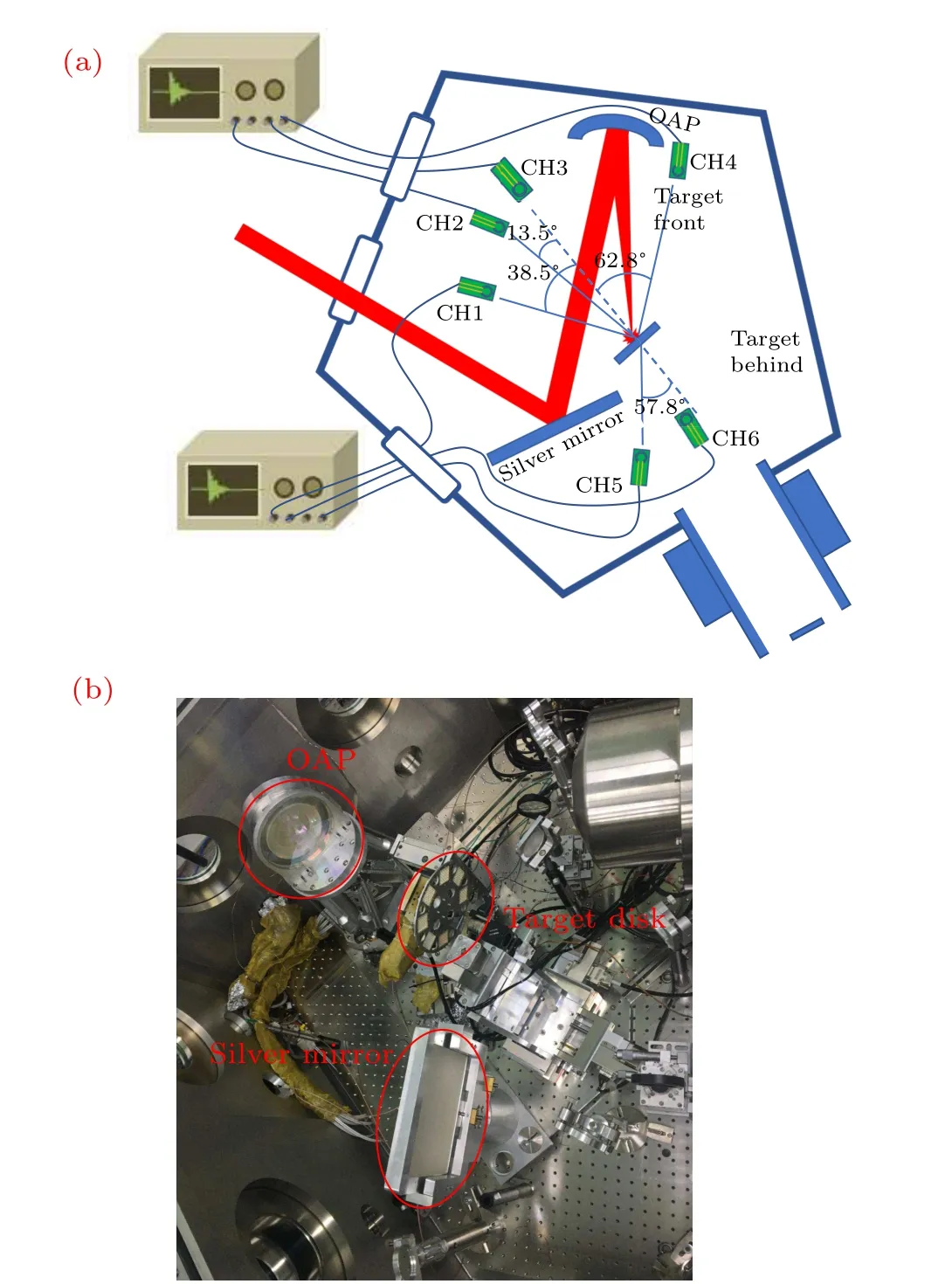
Fig. 1. (a) Schematic layout of the experimental setup at CLAPA and (b)site picture of target arrangement. The intense laser pulse was focused by an OAP mirror onto a target disk with more than three hundred targets, which was mounted on an automatic electrical motor system. A silver mirror was deployed to reflect the laser pulse. Six B-dot antennas (CH1 to CH6) were employed to measure the EMP generated by the laser interacting with solid targets at different positions.
3. Results and discussion
The EMP signals of the laser irradiating different metal targets were firstly measured by a small B-dot antenna(CH1).The corresponding peak voltages (the highest spike value) of the EMPs were analyzed to reveal the relationship between the EMP radiation and the target composition as shown in Fig. 2. The amplitudes of the EMPs show fluctuations from nearly 0.13 to 0.19(RMSE)for each type of target with identical laser conditions. For the aluminium target, the average peak voltage of the EMPs tends to increase with target thickness from 1.8 μm to 70 μm, mainly because of the effect of potential barrier Δφ.[19]The fraction of electrons that can possibly escape from the target is limited byε ≥eΔφ(εis the energy of electron). According to the charging model,the differential charge density in the thinner target is much higher than that in a thicker target assuming that the same number of hot electrons escape from the target interaction with the same laser beam,[18]which induces a larger potential barrier Δφ,increasing the difficulty of hot electrons escaping and resulting in EMP emissions.
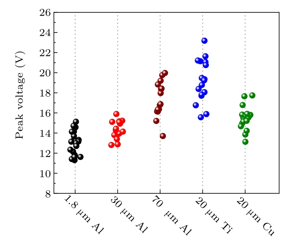
Fig.2. Peak voltage of the EMPs for laser irradiation of different metal targets.
In addition,with the same thickness,titanium targets can produce more abundant electromagnetic radiation compared to copper targets, which can be attributed to difference in work functions between different metals. Since the work functions of aluminum (4.2×10?19J) and copper (4×10?19J) are weaker than that of titanium(6.6×10?19J),the plasma cloud is easier created for aluminium and copper,which hinders the propagation and adsorption of the laser and decreases the amplitude of EMP.[10]
The variation of the EMPs during a laser—CH target relative position scan was recorded, as shown in Fig. 3(a). The thickness of the CH target was 5 μm. Note that the initial position at 0 is deemed as the reference position, where the focal spot of the low power laser coincides with the front of the target surface. The target was moved along the path of the focused laser at an interval of 50 μm with an accuracy of 1 μm. The anteroposterior positions are labeled with positive and negative numbers. The shifting of the target position affected the on-target intensity of the laser pulse, hence further decreasing the intensity of the EMPs. It can be seen that the EMPs show little change when the target moves from?100 μm to 100 μm, consistent with the Rayleigh lengthZRof the laser. The Rayleigh length can be calculated asZR=πω0/λ=98.2 μm, whereωis the beam waist andλis the wavelength of laser. The maximum EMP signal appears at 100μm and then it gradually decays when the target shifts further.
During laser irradiation of the CH target, the change of physical distance has a great influence on electron density,which is proved to be positively correlated with the intensity of EMPs.[28]A multi 1D simulation is thus constructed to calculate the electron density around the target in varying target positions under laser irradiation. As shown in Fig.3(b),most electrons are generated before the target during laser—target interaction. Laser self-focusing in the plasma can partially counteract the impact from target shifting,resulting in the stability of the EMPs in the scope of the target shifting distance(within 100 μm). When the target shifting distance exceeds the Rayleigh length of the laser, the deterioration of the focal radius of the laser and a decrease in the electron density of the plasma bring about a decrease in EMP intensity. The relationship between EMP amplitudes and emitted electrons was theoretically and experimentally confirmed by our previous simulations.[28,29]
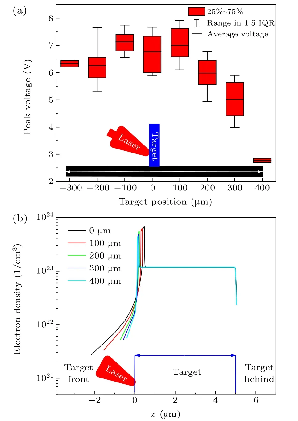
Fig. 3. (a) Evolution of the EMPs recorded with varying laser—CH target coupling positions and(b)simulated electron density around the target in the cases of varying laser—CH target coupling positions. The thickness of the CH target was 5μm.
With the 5μm CH plastic target,effective proton acceleration was also observed. Using the quadrupole triplet,the protons with 3.5 MeV central energy were focused on the scintillator, and the energy spread within the beam spot region was around 30%.[30]Figure 4(b) shows the relationship between the intensity of the EMPs recorded by CH4—CH6 and the count of the proton signals on the scintillator during the laser—target coupling position scan in Fig.3.The count of the proton signal is proportional to the charge of the focused protons. The data acquired at different target positions are represented by different symbols. This indicates that the charge of protons with central energy of 3.5 MeV are exponentially increased when the EMP signal reaches 4 V for CH6,and around 6 V for CH4 and CH5. Figure 4(a)shows the comparison of the fluctuated EMP raw signals(recorded at CH4)with their correspondingscintillator images of the focused 3.5 MeV proton at the target position of?200 μm (above) and?100 μm (below). It can be seen that the peak voltage of the EMPs recorded at CH4 has the same tendency with the protons. Therefore, although both the protons and the EMPs gain energy from the laser,no competitive effect is found between them,suggesting that the energy transfer efficiency from the laser is not high. Since the sources of EMPs are mainly attributed to emitted electrons and the target neutralization current,[4,5,8,17]protons in Fig. 4(b)contribute partially to EMPs.
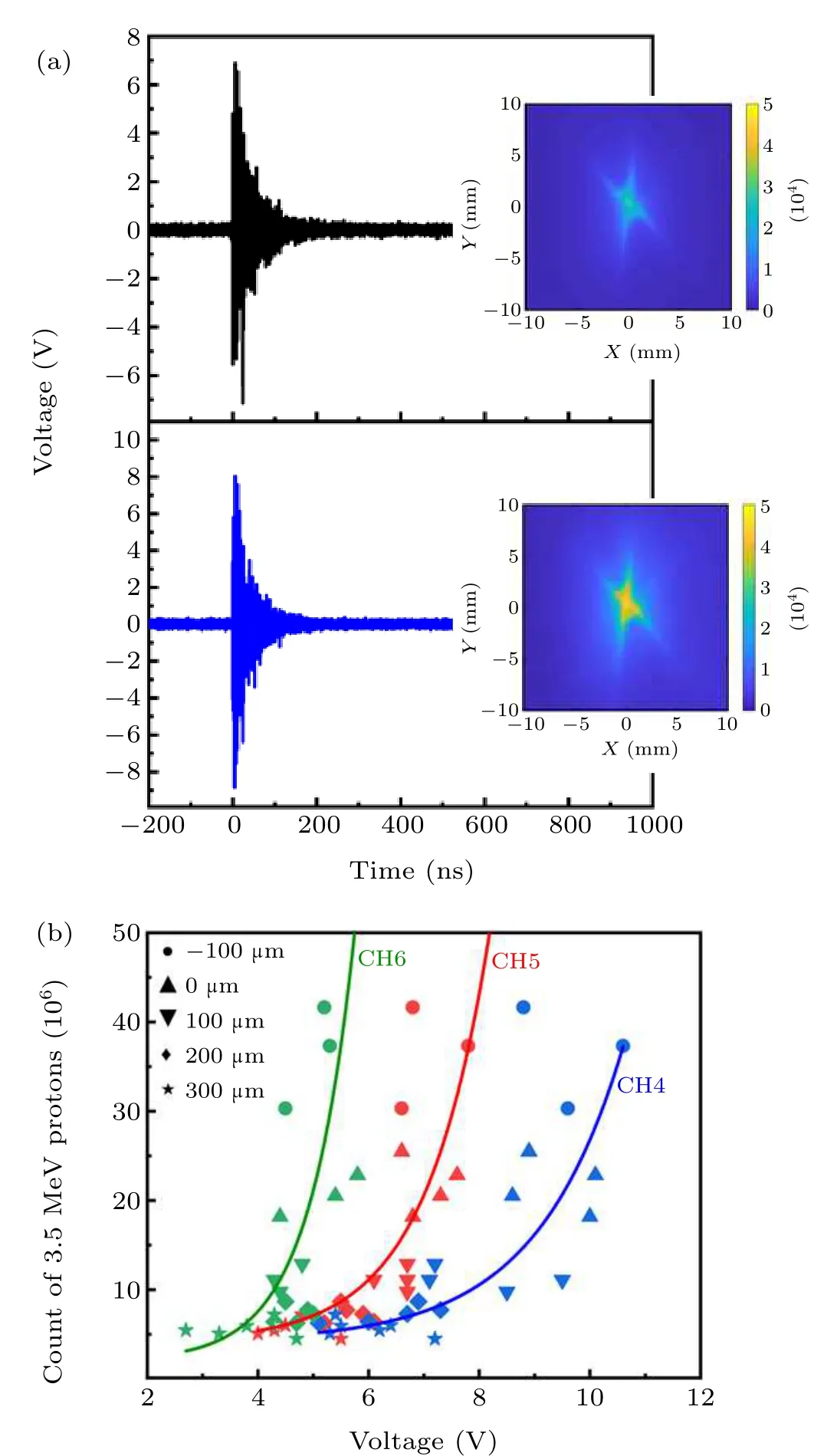
Fig.4. (a)Comparison of the fluctuated EMP signals(recorded at CH4)with their corresponding scintillator signals in different laser shots and(b)correlation between the protons with a central energy of 3.5 MeV and the voltage of the EMPs recorded at three positions(CH4 to CH6)in various target positions.
The uncertainty of the produced plasma and the energy jitter of the laser together result in fluctuations of the EMPs as shown in Fig. 5 with the same laser shooting conditions.During relatively short laser shot intervals,the EMPs detected at the front of the target for each shot are weaker than those behind the target. Signals at the front of the target show a fluctuation of 0.85 RMSE,while fluctuation for signals behind the target is 0.16 RMSE, as shown in Fig. 5(a). Both signals are normalized to 1 meter position using 1/r2scaling.[31]Since CH4 and CH5 were surrounded by different equipment, FFT signals measured at these two positions show a distinct difference,especially at higher frequencies(0.8 GHz—2 GHz)as shown in Fig.5(b).
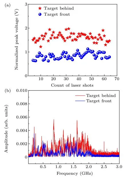
Fig. 5. (a) EMP signals detected by two B-dot antennas (CH4 and CH5)located at the front of the target and behind the target respectively for laser pulses continuously shooting on CH(plastic)targets of 5μm thickness and(b)the corresponding frequency spectra obtained by FFT.
The propagation of EMP in target chamber follows the wave equation:

whereEis the electric field,μ0the permeability of vacuum,ε0the permittivity of vacuum,andandηi≈∞Ω the wave impedance of the vacuum and iron, respectively. As EMPs propagate from the target source through the vacuum to the chamber wall, there is a fierce change of wave impedance,resulting in the reflection of EMP with little energy loss.
A 3D model is constructed to reveal propagation of resonant EMPs according to the geometrical parameters of the CLAPA chamber by the HFSS program. We assume a single source of EMP,which is stimulated by an electric currentpulse. As can be seen from Fig.6,the EMPs reach the chamber wall at 4 ns and are reflected afterwards inside the chamber.A continuous reflection of EMPs inside the chamber takes place, resulting in its uniform phase diversity. EMP gradually spreads to fill out the chamber during the oscillation with a mode strongly relying on the configuration of the chamber,and attenuates 4.8 dB in 46 ns.In the experiment,the positions of the mirror frame and the target frame are often adjusted in the simulation process;we found that the propagation process of the electromagnetic pulse was mainly determined by the geometric configuration of the target chamber, which had little relationship with the mirror frame and the target frame,so they were not considered in the modeling. Although the accessories have little effect on the overall trend of EMP propagation, the metal components of the mirror frame and target frame can possibly cause perturbations and reflections of EMPs at a small scale,which can be observed occasionally by using antennas placed in coincidental locations. These perturbations bring slight changes to the intensity of EMPs and add frequency components individually, but these effects are submersed in wide-band and complex frequency spectra of the EMPs.
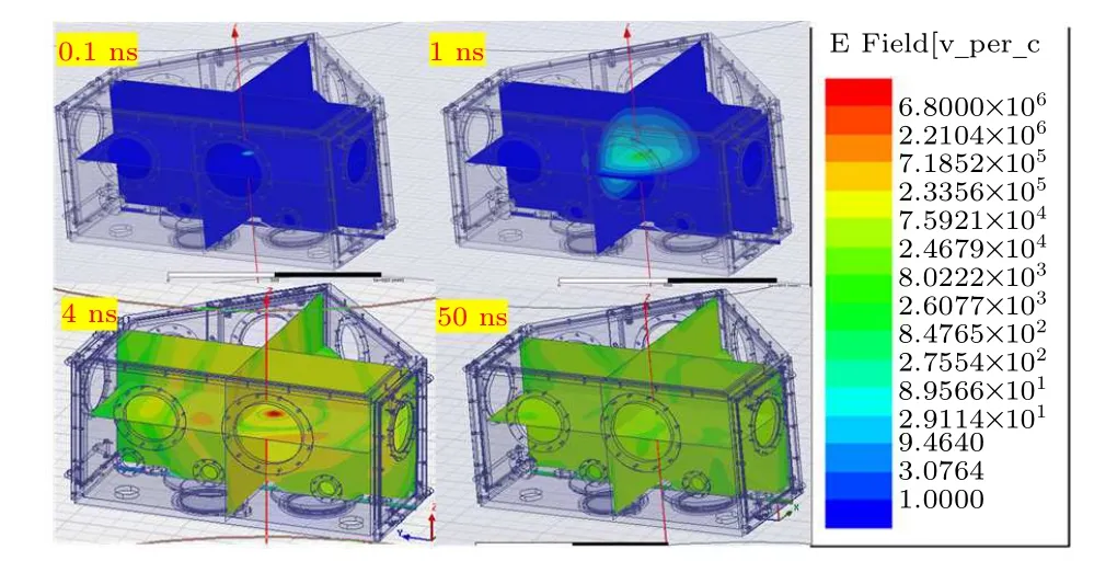
Fig. 6. HFSS model for the propagation of EMPs inside the CLAPA target chamber.
In addition,beat frequency occurring in EMP signal was specifically detected by the antenna CH5. Figure 7 shows the short time Fourier transform of one typical EMP signal during the interaction between the laser and the CH plastic target,and its corresponding time-domain signal provides direct evidence of the resonance of the EMPs inside the laser chamber.EMPs measured behind the target consist of two phases: an initial phase dominated by higher frequencies and a resonant phase after 200 ns. In Fig. 7(a), the EMP signal in the time domain shows typical features of beat frequency, suggesting that there is a single-frequency wave modulated over higher frequencies. As the period of the beat frequency is around 100 ns, the wavelength of the single-frequency wave can be calculated byλ=c/f=30 m(10 MHz),where c is the speed of light in a vacuum. Accordingly, in Fig. 7(b), at the initial 200 ns, the dominant EMP frequencies of up to 1.2 GHz are superimposed on the resonant signal. After 200 ns, the multiple frequency compositions at the initial 200 ns are replaced by two dominated frequencies: a carrier wave ranging from 75 MHz to 375 MHz, and a carrier wave of 10 MHz. The attenuation in a vast range of frequencies except specific frequencies (75—375 MHz and 10 MHz) provide clear evidence of resonance.Note that the wave crest of the standing waves in the time domain corresponds well to the crest of the amplitude in frequency,and the resonance of EMP lasts for 300 ns.
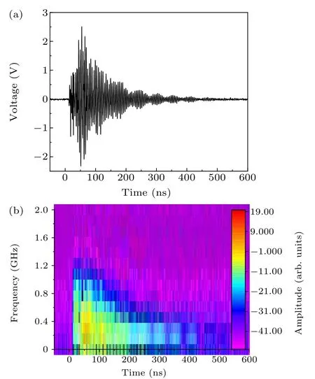
Fig. 7. (a) Time-resolved EMP signal detected behind the target. (b) Frequency spectra of EMP signal in the same shot. There is a temporal correspondence between time variations in the frequency and time variations in the voltage of the standing wave.
Considering that the EMPs are generated in the process of laser—target interaction, the space around the antennas is free of EMP sources. As shown in Fig.8(a),the frequencies of the EMP signals vary with the positions of the antennas(CH1 to CH4)set in front of the target,further confirming that the complex layout of the equipment and auxiliary materials inside the chamber affects resonant process,for example,the large superficial areas such as the silver mirror and the drive motor inside the chamber. An EMP detected by CH4 located in a narrow space between the OAP and chamber wall has a lower frequency domain, ranging from around 100 MHz to 600 MHz,which is closely related to laser pulse.[32]However,typical frequencies of EMPs detected at a broader space(CH1)are more concentrated in a specific domain,indicating that less nonlinear interaction occurs where the layout of the equipment is arranged openly. In addition,changing the position has a huge impact on the energy collection of antennas. The accumulated power of the four positions is presented in Fig. 8(b). On account of the differences in resonant mode,EMP power in openspace is much larger that in narrow regions. The small-scale structures can disrupt the uniformity of EMP,[23]leading to energy loss and shift of its frequency. When EMPs propagate through the laser chamber, currents are induced on metallic components,ultimately resulting in the wide frequency distribution of the EMPs. All in all, the EMP signals obtained in this study are mainly attributed to the neutralization current and the particles on the surfaces.
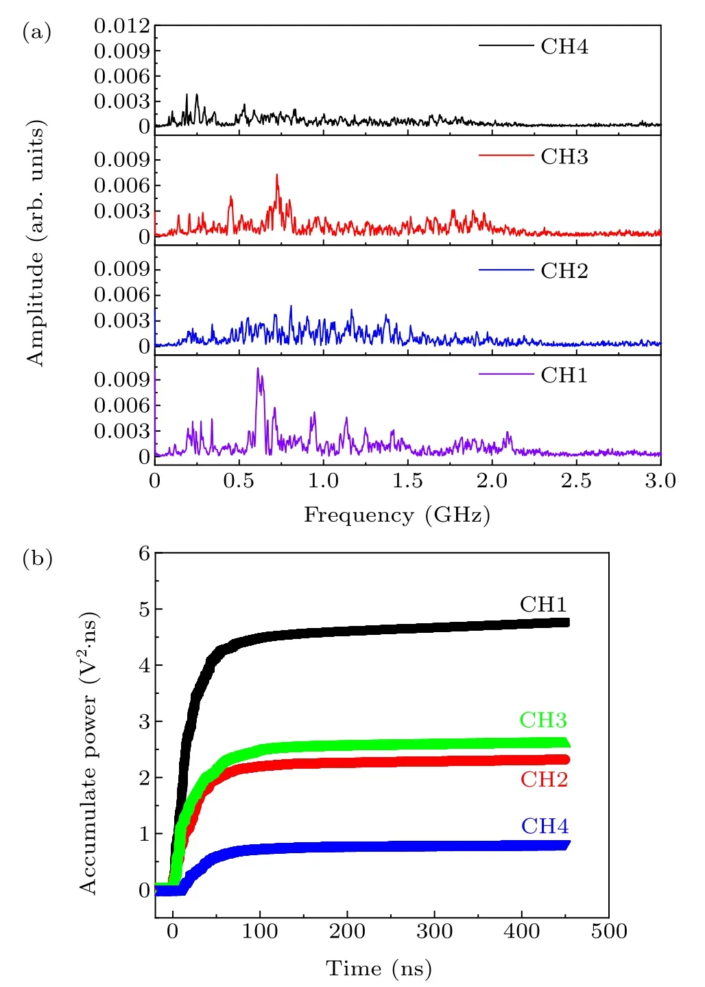
Fig.8.(a)Spatial distribution of EMPs in frequency domain recorded by four small dot antennas(these small dot antennas are localized at four positions in front of the target as shown in Fig.1)and(b)the corresponding accumulated power. Both amplitude and accumulation power are normalized to 1 meter.
4. Conclusion
Electromagnetic radiation distribution and intensity is studied based on a statistical laser shooting solid targets at CLAPA. The relationship between the generation of protons and EMPs is revealed. Possible chamber resonance in the chamber can have a significant impact on EMPs. A typical standing wave is obtained and analyzed to supply clear evidence of the resonance of EMPs inside the laser chamber.
Acknowledgments
Project supported by the National Natural Science Foundation of China (Grant Nos. 11975037 and 11921006) and the National Grand Instrument Project of China (Grant Nos.2019YFF01014400 and 2019YFF01014404).
- Chinese Physics B的其它文章
- A broadband self-powered UV photodetector of a β-Ga2O3/γ-CuI p-n junction
- High-sensitive terahertz detection by parametric up-conversion using nanosecond pulsed laser
- High efficiency,small size,and large bandwidth vertical interlayer waveguide coupler
- High-fidelity resonant tunneling passage in three-waveguide system
- An analytical model for cross-Kerr nonlinearity in a four-level N-type atomic system with Doppler broadening
- Determine the physical mechanism and source region of beat wave modulation by changing the frequency of high-frequency waves

