Conceptual design and heat transfer performance of a flat-tile water-cooled divertor target
Lei LI (李磊),Le HAN (韓樂),Pengfei ZI (訾鵬飛),Lei CAO (曹磊),Tiejun XU (許鐵軍),Nanyu MOU (牟南瑜),Zhaoliang WANG (王兆亮),Lei YIN (殷磊) and Damao YAO (姚達毛)
Institute of Plasma Physics,Chinese Academy of Sciences,Hefei 230031,People’s Republic of China
Abstract The divertor target components for the Chinese fusion engineering test reactor(CFETR)and the future experimental advanced superconducting tokamak (EAST) need to remove a heat flux of up to ~20 MW m?2.In view of such a high heat flux removal requirement,this study proposes a conceptual design for a flat-tile divertor target based on explosive welding and brazing technology.Rectangular water-cooled channels with a special thermal transfer structure (TTS)are designed in the heat sink to improve the flat-tile divertor target’s heat transfer performance(HTP).The parametric design and optimization methods are applied to study the influence of the TTS variation parameters,including height (H),width (W*),thickness (T),and spacing (L),on the HTP.The research results show that the flat-tile divertor target’s HTP is sensitive to the TTS parameter changes,and the sensitivity is T>L>W*>H.The HTP first increases and then decreases with the increase of T,L,and W*and gradually increases with the increase of H.The optimal design parameters are as follows: H=5.5 mm, W*=25.8 mm, T=2.2 mm,and L=9.7 mm.The HTP of the optimized flat-tile divertor target at different flow speeds and tungsten tile thicknesses is studied using the numerical simulation method.A flat-tile divertor mock-up is developed according to the optimized parameters.In addition,high heat flux(HHF)tests are performed on an electron beam facility to further investigate the mock-up HTP.The numerical simulation calculation results show that the optimized flat-tile divertor target has great potential for handling the steady-state heat load of 20 MW m?2 under the tungsten tile thickness<5 mm and the flow speed ≥7 m s?1.The heat transfer efficiency of the flat-tile divertor target with rectangular cooling channels improves by ~13%and ~30%compared to that of the flat-tile divertor target with circular cooling channels and the ITER-like monoblock,respectively.The HHF tests indicate that the flat-tile divertor mock-up can successfully withstand 1000 cycles of 20 MW m?2 of heat load without visible deformation,damage,and HTP degradation.The surface temperature of the flat-tile divertor mock-up at the 1000th cycle is only ~930 °C.The flat-tile divertor target’s HTP is greatly improved by the parametric design and optimization method,and is better than the ITER-like monoblock and the flat-tile mock-up for the WEST divertor.This conceptual design is currently being applied to the engineering design of the CFETR and EAST flat-tile divertors.
Keywords: CFETR,heat transfer performance,parametric design and optimization,HHF tests,flat-tile divertor target
1.Introduction
Particle and power exhaust are key issues for the next-step fusion reactors.Divertors must be designed to handle power exhaust.The power handling capacity of divertors is less than or comparable to that of the international thermonuclear experimental reactor(ITER)design of 10 MW m?2under the DEMO operation condition.It is 5–7 MW m?2for a conventional monoblock design with tungsten (W) and ferritic steel as the plasma-facing and structure materials,including the water-cooling pipe,respectively [1],and will increase to the 10 MW m?2level for advanced target designs with helium-cooled W-alloy and oxide dispersion-strengthened(ODS)/ferritic steels [2].Studies have indicated that the power decay length λq,which is a crucial quantity related to the divertor peak load(qmax),is predicted as λq≈1 mm withIp=15 MA for the ITER[3].This value is much lower than the previous projected width of ≈5 mm,suggesting a significantly larger divertor peak load to the divertor target.Therefore,a new divertor structure that can sustain the power exhaust strike of fusion devices like the CFETR must be developed.
The EAST machine achieved a 101.2 s H-mode discharge target in 2017,and its next goal is to achieve more than 400 s in H-mode discharges.Its future goal is to achieve 1000 s [4–6].Therefore,the divertor heat load will be over 15 MW m?2in the future [7,8].However,the current EAST divertor structure cannot meet the future plasma configuration.As shown in figure 1,the lower divertor in the EAST is covered by water-cooled graphite tiles with a power handling capability of ~2 MW m?2.Although the upper divertor is a water-cooled full-tungsten divertor with a power handling capability of ~10 MW m?2[9,10],it is far from the requirements of future heat loads on divertor targets.Notably,the ITER-like monoblock structure has been successfully applied to some tokamak devices,such as EAST,WEST,and JT-60SA; however,the structure has some limitations.For example,the process involving different bonding technologies is complicated.The hot radial pressing and hot isostatic pressing technologies are applied to W/Cu and CuCrZr/Cu bonding.Electron beam welding is used in connection to monoblock PFUs and the end box.Meanwhile,inconel legs are bonded on monoblock by brazing.The high temperature during bonding can result in structural degradation.The W/Cu bonding temperature is up to 900 °C,which is maintained for approximately 2 h,whereas the CuCrZr/Cu bonding temperature is 500°C–600°C,which is maintained for approximately 3 h [9,10].The circular cooling pipe in the monoblock does not have a better heat exchange efficiency than the rectangular cooling pipe.This kind of structure leads to its heat transfer capability being unable to reliably sustain the steady-state heat load more than 20 MW m?2during several seconds [9–14].The forced-cooled monoblock-type CFC target on JT-60SA could withstand a maximum heat flux of ~15 MW m?2for 100 s [15].The high-performance W monoblock mock-up in EUDA could be subjected to HHF tests of 300 cycles at 20 MW m?2,which is not enough for fusion devices [16–20].The helium-cooled tungsten divertor designed for DEMO-type fusion reactors has a good heat load removal capability of 10–15 MW m?2,but its disadvantage is a complicated structure [21,22].Therefore,searching for a new divertor target design is very important both for CFETR and EAST.
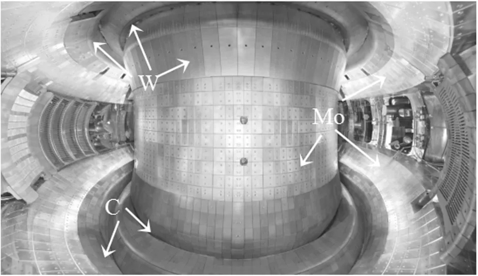
Figure 1.Material distribution of the plasma-facing components in the EAST machine.
Explosive welding technology (EWT) and brazing technology(BT)have been widely used in recent years,especially in the welding of different metal materials,because of their advantages of high welding strength,low cost,simple process,and high production efficiency.EWT can be used for manufacturing an ITER-grade 316 L(N)/CuCrZr hollow structural member and W/CuCrZr plasma-facing components[23–25].BT could be used for bonding tungsten tiles to heat sinks.EWT and BT are currently being applied to the 2.45 GHz lower hybrid wave (LHW) antenna limiter in the EAST.The LHW antenna performed well after a round of experiments in 2020.
Complex water-cooled channels,such as HyperVapotron,rectangles,and arbitrary shapes,which help improve the heat exchange efficiency of the structure,can easily be obtained based on EWT.A structure with water-cooled channels forms a closed and complete cooling structure called the divertor target heat sink by EWT [26–30].The heat sink bonded by two metal plates can be of different material combinations,such as CuCrZr/316 L,ODS-Cu/ODS-steel,and ODS-Cu/clam.CuCrZr and ODS-Cu have good thermal conductivities and can be used as the upper heat sink plate.316 L,ODS-steel,and clam steel have good mechanical performances,an excellent welding ability,and a higher degradation temperature.They can also be used as the lower heat sink plate.The lower heat sink plate can play a strengthening role when the high temperature in the bonding process of CuCrZr/W or ODS-Cu/W induces a decrease of the mechanical performance of the upper heat sink plate.
Section 2 presents the conceptual design for the flat-tile divertor target.The influence of the TTS variation parameters on the flat-tile divertor target’s HTP is studied through the parametric design and optimization method in section 3 to obtain the best design parameters of the TTS.The flat-tile divertor target’s HTP is investigated by numerical simulation calculations and HHF tests in sections 4 and 5,respectively.Finally,section 6 provides the summary and outlook of the study.
2.Conceptual design for the flat-tile divertor target
Figure 2 shows that the flat-tile divertor target is mainly composed of seven parts,namely tungsten or tungsten alloy tiles(A),oxygen-free copper(OFC)interlayer(B),upper heat sink plate(C),lower heat sink plate(D),outlet pipe(E),inlet pipe (F),and support legs (G).The overall size of the structure is 217×162×20 mm3.The thicknesses of A–D are 2 mm,1 mm,11 mm,and 6 mm,respectively.The heat sink consists of parts C and D combined by EWT.Part A is bonded to part C by BT.Part B is used as the interlayer between parts A and C.Part E,part F and part G are bonded to the lower heat sink plate using argon arc welding.
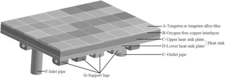
Figure 2.Schematic diagram of the flat-tile divertor target structure.
Figure 3 depicts the water-cooled channels with special TTS made in the upper heat sink plate before explosive welding.Figures 4 and 5 show the cross-section and longitudinal section schematic diagrams of the flat-tile divertor target,respectively.
This study focuses on the divertor HTP,not the material itself; hence,suitable materials can be chosen according to materials science development.The candidate material for part A is pure tungsten or potassium-doped tungsten (KW).The candidate material combination for the heat sink is CuCrZr/316 L or ODS-Cu/ODS-steel or ODS-Cu/clam.The candidate materials for the outlet pipe,inlet pipe and support legs are the same as the lower heat sink.
After investigation,it is found that there are few manufacturers in China that can produce KW,ODS-Cu,and ODS-steel in large quantities,and they are still in the research and development stage.In addition,the good material properties claimed by many manufacturers,such as thermal conductivity,yield strength,degradation temperature,and other physical parameters,were very different from those in our actual test results.At present,we have not obtained real and reliable material property parameters.Therefore,the material combination W/CuCrZr/316 L(N) was selected for research to study the HTP of the flat-tile divertor target.

Figure 3.Heat sink with water-cooled channels.
3.Parametric design and optimization
The water-cooled channel dimensions wereH0=8 mm andW0=30 mm(figures 4 and 5).The TTS design parameters are as follows: heightH=3.5–5.5 mm; widthW*=20–28 mm;thicknessT=1–3 mm; and spacingL=4–11 mm.The design parameters were relevant to the TTS; thus,the computational model was simplified to the model shown in figure 6.The cooling medium was water,regardless of the boiling phase.The inlet temperature and the inlet flow speed are 22 °C and 2 m s?1,respectively.The green surface shown in figure 6 was loaded with a heat flux of 10 MW m?2.Table 1 shows the material properties used in the calculations.
To eliminate the grid size influence on the calculation results,the grid independence was analyzed by setting the coarse,medium,and fine grids to 0.6 mm,0.4 mm,and 0.2 mm,respectively.The calculated results were very close;thus,the grid size was selected as 0.4 mm (figure 7).Table 2 lists the parametric design schemes and steady-state thermal analysis results.The response surface optimization tool in ANSYS was used to analyze and optimize the schemes.The screening optimization method was chosen.The number of samples was 5000.The optimization goal was to minimize the maximum temperature of all materials.
The curves in figure 8 show the local sensitivity of the maximum temperature as the design parameters change.The response point represents the optimal design point.The abscissa α indicates the relative location of the design parameter within its value range.Let us take parameterTas anexample:T=2 mm,α=(T?1 mm)/(3 mm?1 mm)=(2 mm?1 mm)/(3 mm?1 mm)=0.5.The maximum temperature gradually decreased asHincreased.The maximum temperature first decreased to the lowest point and then continuously increased asW*orTorLincreased.Therefore,the design parameter size changes significantly affected the cooling efficiency of the structure.The optimal design parameters are as follows:H=5.5 mm;W*=25.8 mm;T=2.2 mm; andL=9.7 mm.Figure 9 and table 3 present the calculation results using the optimal parameters,which were better than those in table 2.
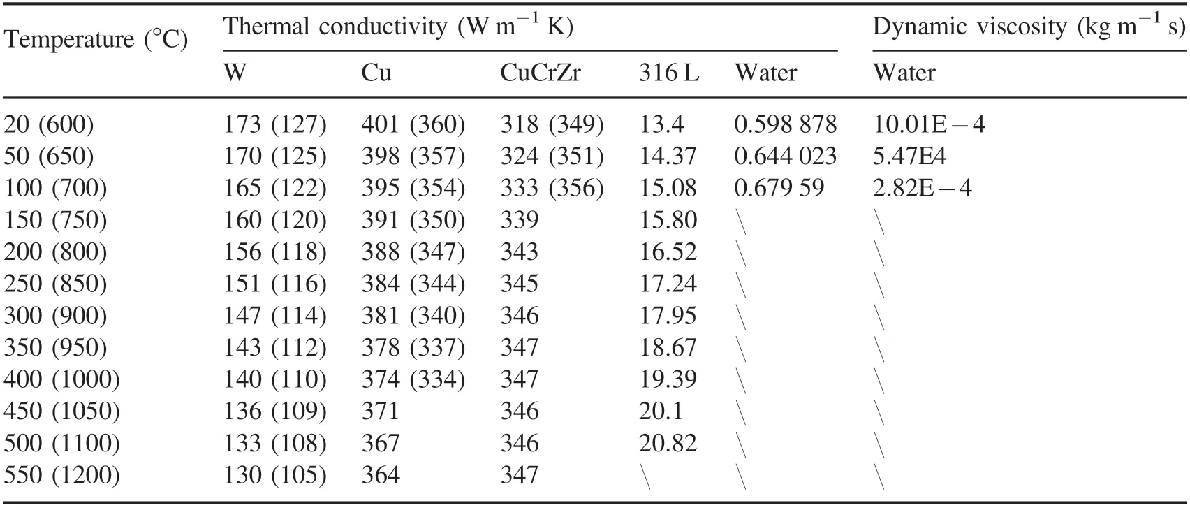
Table 1.Thermal physical properties of the materials.

Figure 4.Longitudinal section view of the flat-tile divertor target.

Figure 5.Cross-section view of the flat-tile divertor target.

Figure 6.Simplified computational model used for the parametric design and optimization.
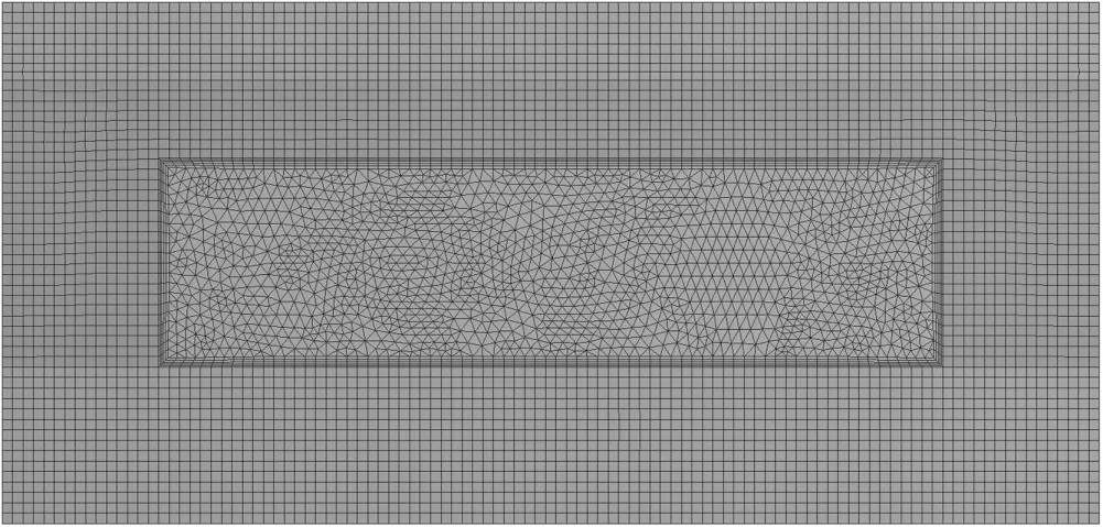
Figure 7.Mesh of the computational model.
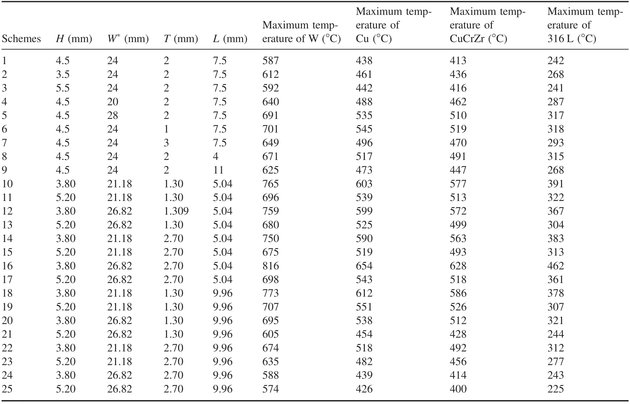
Table 2.Parametric design schemes and calculation results.
Figure 10 shows the local sensitivity of the maximum temperature to different design parameters at the optimal response points.The greater the absolute value of the sensitivity,the greater the influence of the design parameter on the maximum temperature.The order of sensitivity from high to low isP3(T)>P4(L)>P2(W*)>P1(H).Therefore,the TTS thickness change had the greatest impact on the flat-tile divertor target’s HTP,followed by spacingLand widthW*.The least affected was the heightH.
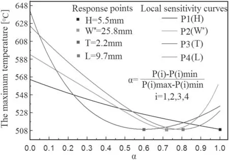
Figure 8.Local sensitivity curves of the maximum temperature as the design parameters change.
4.Heat transfer performance
The conceptual design for the flat-tile divertor tar get is mainly to provide support for the future EAST and CFETR divertors.Therefore,its HTP under 20 MW m?2must be studied.Figure 11 shows the calculated maximum tungsten surface temperature of the flat-tile divertor target at different flow speeds in the cooling channels (equivalent to the flow speeds in the Φ12 mm pipe).The maximum temperature gradually decreased as the flow speed increased; however,the relationship between the two was not linear,but similar to an exponential function.The improvement in the flat-tile divertor target HTP continuously became smaller as the flow velocity gradually increased.To obtain a fine removal of the 20 MW m?2heat flux,the flow speed should be ≥7 m s?1.Tungsten is currently used as a plasma-facing material for EAST divertors.It is also a candidate material for the CFETR divertors.A certain loss of tungsten material is observed during the operation of nuclear fusion tokamak devices.Accordingly,2 mm-thick tungsten tiles are sufficient for EAST divertors,but may not be enough for CFETR divertors.Therefore,as shown in figure 12,the HTP of the flat-tile divertor target under different tungsten tiles thicknesses was studied when the heat flux was up to 20 MW m?2(the flow velocity is ~7 m s?1,the inlet temperature is 22°C,and the inlet pressure is 1 MPa ).The maximum temperature linearly increased as the tungsten tile thickness increased.Meanwhile,the maximum temperature of Cu,CuCrZr,and 316 L decreased by only a few degrees celsius.Therefore,the influence of the tungsten tile thickness on the flat-tile divertor HTP was mainly reflected in the influence of the tungsten surface temperature,while the influence on Cu,CuCrZr,and 316 L was almost negligible.The maximum surface temperatures of W,Cu,CuCrZr,and 316 L are 1330 °C,509 °C,462 °C,and 177 °C,respectively,when the tungsten tile thickness reached 5 mm.The maximum temperature of W exceeded the allowable value of 1200 °C.The maximum temperature of Cu and CuCrZr slightly exceeded the allowable values of 500 °C and 450 °C,respectively.Therefore,the tungsten tile thickness did not exceed 5 mm when the heat flux reached 20 MW m?2.This analysis result was obtained under a peak heat flux width of 24 mm,which is larger than the predicted value of ~5 mm and may be narrower in the future.The allowable temperature of the materials may be greatly increased with the development of plasma-facing materials,such as KW and ODS-Cu.Therefore,this kind of flat-tile divertor target structure has great potential for handling the steady-state 20 MW m?2heat load.
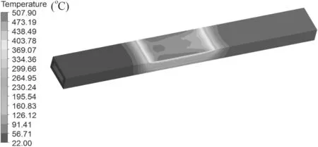
Figure 9.Temperature distribution calculated using the optimal parameters.

Figure 10.Local sensitivity of the maximum temperature to different design parameters.

Table 3.Calculated results using the optimal parameters.

Figure 11.Maximum temperatures of the flat-tile divertor target under different flow velocities.
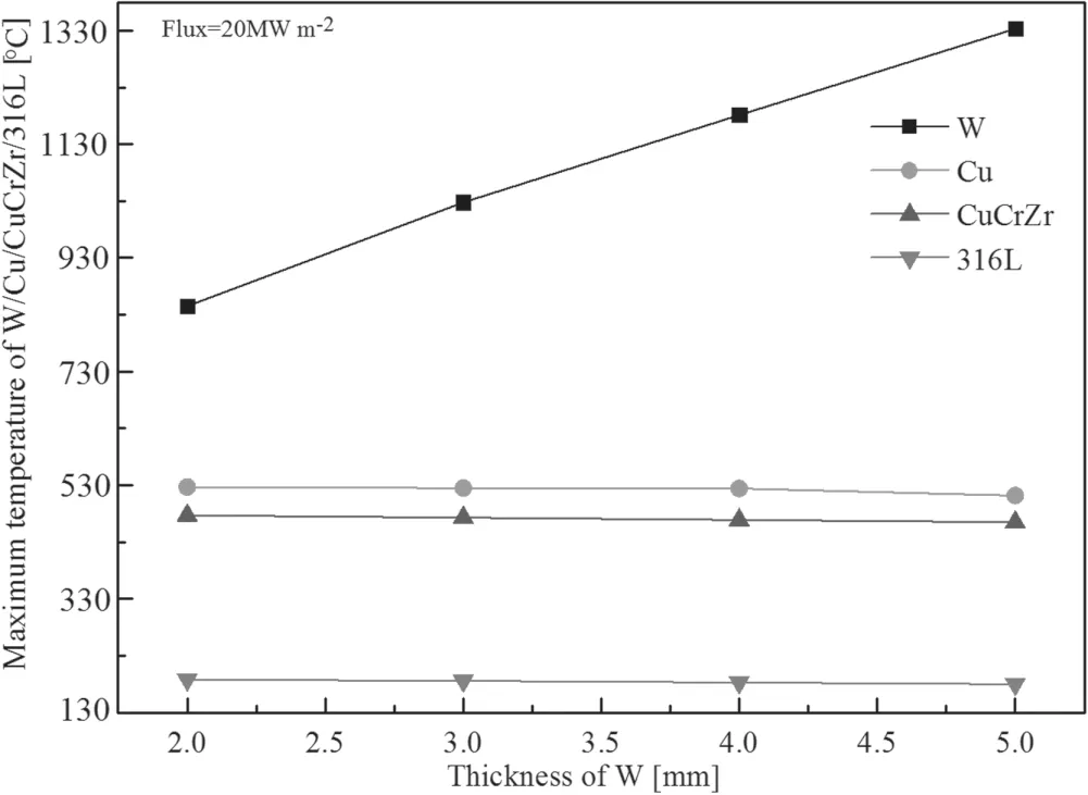
Figure 12.Maximum temperatures of the flat-tile divertor target materials under different tungsten tile thicknesses at 20 MW m?2.
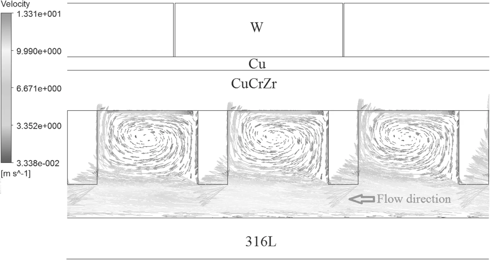
Figure 13.Fluid velocity vector in the rectangular cooling channel of the flat-tile divertor target.
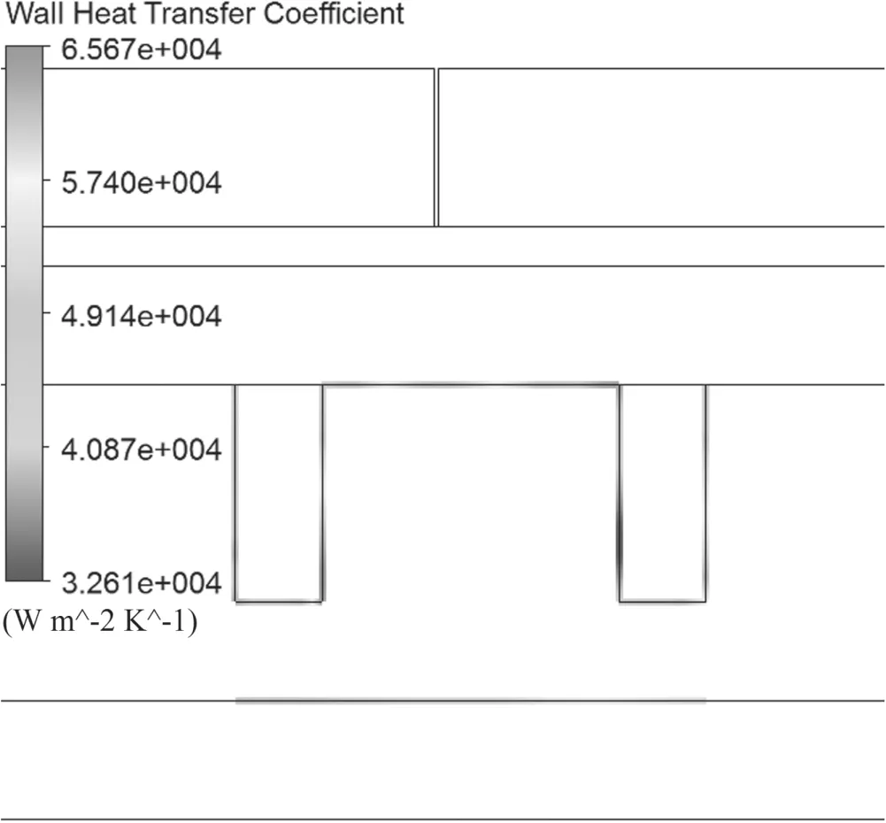
Figure 14.Wall heat transfer coefficient of the rectangular cooling channel for the flat-tile divertor target.

Figure 15.Wall heat transfer coefficient of the circular cooling channel for the flat-tile divertor mock-up.
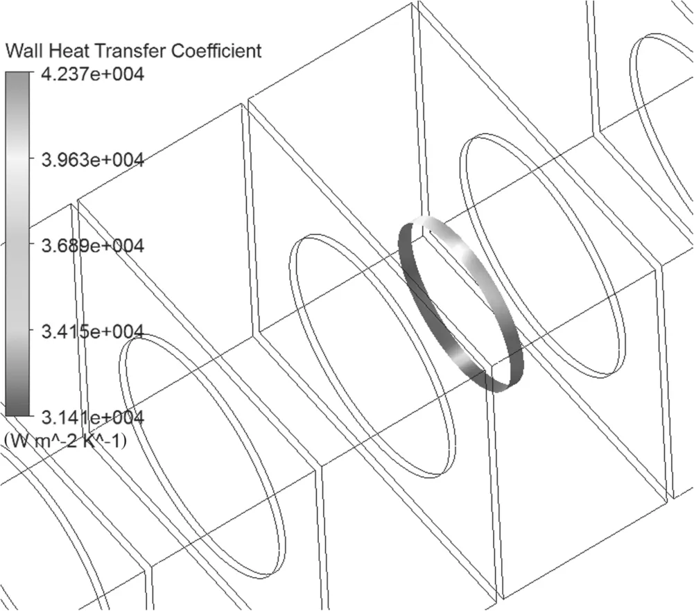
Figure 16.Wall heat transfer coefficient of the circular cooling pipe for the ITER-like monoblock.

Figure 17.Temperature of the flat-tile divertor target with rectangular cooling channel (tungsten tile thickness: 4 mm).
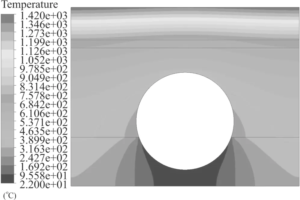
Figure 18.Temperature of the flat-tile divertor target with circular cooling channel (tungsten tile thickness: 4 mm).
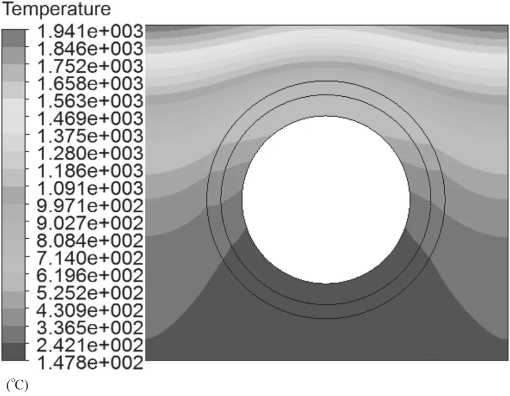
Figure 19.Temperature of the ITER-like monoblock with circular cooling pipe (distance from the W surface to the OFC: 4 mm).
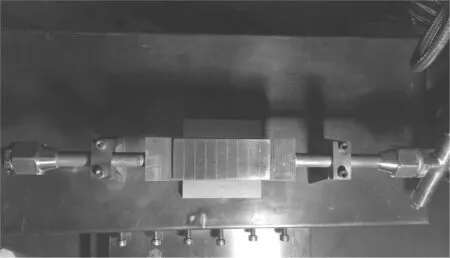
Figure 20.The flat-tile mock-up in the electron beam facility.
Figure 13 shows the fluid velocity vector in the rectangular cooling channel.A strong disturbance zone was formed in the upper turbulence structure,which can improve the heat transfer efficiency.Heat was transferred to the lower smooth flow zone to be taken away by the water with a higher flow velocity.The heat transfer coefficient (HTC) range for the flat-tile divertor target with rectangular cooling channels is 32,608–65,669.1 W m?2K?1(figure 14),which is larger than the HTC for the flat-tile divertor target with circular cooling channels(31,520–64,450 W m?2K?1,see figure 15),and the HTC for the ITER-like monoblock with circular cooling pipe(31,407–42,370 W m?2K?1,see figure 16) under the same conditions of the heat flux (20 MW m?2),inlet flow velocity(~7 m s?1),and distance from the W surface to the OFC(4 mm).Compared with the circular cooling channel,the heat transfer efficiency of the rectangular cooling channel was increased by ~13% on average,and the maximum temperature was reduced by ~255°C(figures 17 and 18).Compared with the ITER-like monoblock,the heat transfer efficiency for the flat-tile divertor target with rectangular cooling channels increased by ~30% on average,and the maximum temperature decreased by ~776 °C (figures 17 and 19).
5.High-heat flux tests (HHF)
Figure 20 shows a kind of flat-tile divertor mock-up that contains nine thin tungsten tiles brazed to a copper alloy heat sink with 1 mm OFC as an interlayer.The flat-tile mock-up has a dimension of 163.5 mm (length)×44.5 mm(width)×22.5 mm (height).The W-tiles are 44.5 mm width,2 mm thickness and 11.5 mm axial length.The HHF tests of the flat-tile mock-up were performed using a 30 KW electron beam facility.The tungsten surface temperature was measured using a non-contact stationary digital infrared pyrometer and ranged from 300 °C to 2000 °C.

Figure 21.The flat-tile mock-up after 1000 cycles of 20 MW m?2 heat load.
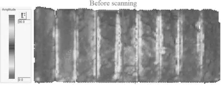
Figure 22.Initial ultrasonic flaw detection image of the flat-tile mock-up.
The scanning area of the tungsten surface was 42 mm×14 mm.The mock-up was loaded with 15 s on and 15 s off and actively cooled by water with an inlet temperature of ~25 °C and a flow speed of ~7 m s?1(inlet pipe of Φ12 mm).The absorbed power densityPabswas calculated using formula (1):

where ρ is the water density (kg m?3);cis the specific heat of water (J kg?1K?1);Qis the flow rate (m3s?1); ΔTis the temperature difference between the outlet and inlet(°C);andS0is the scanned area of the mock-up surface(m2).The absorption coefficient ε is defined in formula (2):

whereUis the acceleration voltage (kV),andIis the incident current (mA).
The ε value is ~61%under different electron beam powers.The mock-up successfully withstood a heat load of 20 MW m?2for 1000 cycles without visible damage and deformation(figures 21–23).Figure 24 shows the surface temperature values of the mock-up under 1–1000 cycles of heat loads.The maximum surface temperature was ~820°C at the first cycle,which is in a good agreement with the numerical simulation calculation result(~810 °C,figure 25).The maximum surface temperature was stable at approximately 930 °C at the 200–1000th cycle,indicating no significant degradation of the mock-up HTP between the first and last cycles.The surface temperatures of the tested ITER-like monoblock mock-ups under 20 MW m?2heat flux were>2000°C[17].The surface temperatures of the flat-tile mock-ups for WEST divertor(W-tiles of 30 mm-width,2 mmthickness and 12 mm axial length) were typically ~1290 °C[31].Therefore,the heat removal capacity of this flat-tile mockup based on rectangular (hypervapotron) water-cooled channels has a great advantage over the ITER-like monoblock and the WEST flat-tile mock-up.
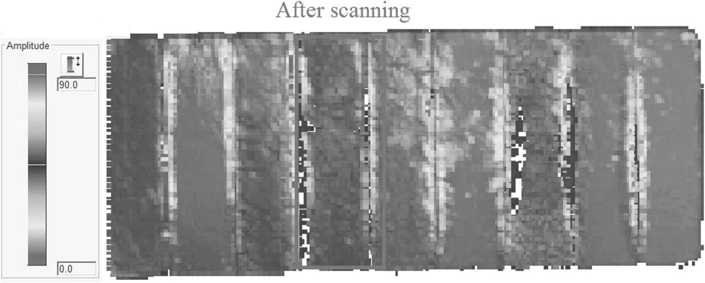
Figure 23.Ultrasonic flaw detection image of the flat-tile mock-up after a heat load of 20 MW m?2 for 1000 cycles.
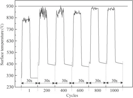
Figure 24.Surface temperature values of the flat-tile mock-up under a cyclic heat load of 20 MW m?2 at the 1st,200th,400th,600th,800th,and 1000th cycles.

Figure 25.Calculated temperature image of the flat-tile mock-up under the 20 MW m?2 heat load.
6.Summary and outlook
A conceptual design for the flat-tile divertor target with rectangular water-cooled channels and special TTS inside was proposed herein.The parametric design and response surface optimization method was applied to study and improve the HTP of the flat-tile divertor target.
The research results indicated that the special TTS parameters greatly influenced the HTP of the flat-tile divertor target,and the influence degree wasT>L>W*>H.The optimal design parameters are as follows:H=5.5 mm;W*=25.8 mm;T=2.2 mm; andL=9.7 mm.
The HTP of the optimized flat-tile divertor target was studied by numerical simulation calculations and HHF tests.The numerical simulation calculations showed that the heat transfer efficiency for the flat-tile divertor target with rectangular cooling channels was ~13% and ~30% higher than that of the flat-tile divertor target with circular cooling channels and the ITER-like monoblock,respectively.A flat-tile divertor mock-up was manufactured through EWT and BT,and tested on an electron beam facility.The HHF test results indicated no obvious HTP degradation and no visible damage and deformation of the mockup during the 1000 cycles of 20 MW m?2heat load.The surface temperature of the mock-up ranged from ~820 °C to ~930 °C during the 1st to the 1000th cycles,which is in a good agreement with the numerical simulation results.However,the HTP of the flat-tile divertor target was greatly improved by the parametric design and response surface optimization method,and was better than the ITER-like divertor monoblock and the WEST flat-tile divertor mock-ups.
This work is pre-research work for the CFETR and future EAST divertors.The conceptual design of the flat-tile divertor target is currently applied in the engineering design for the CFETR flat-tile divertor targets(figure 26).The latest plan for the upgrade of the EAST lower divertors is that three-quarters of the lower divertors are designed to be an ITER-like monoblock structure similar to the EAST upper divertors,and the other quarter is designed to be a flat-tile divertor structure(figure 27).These are in the manufacturing process,and are expected to be installed in EAST in the first half of 2021.
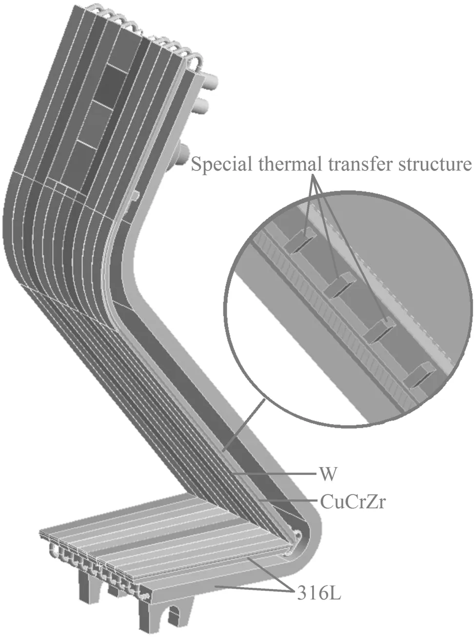
Figure 26.The flat-tile outer divertor target for CFETR.
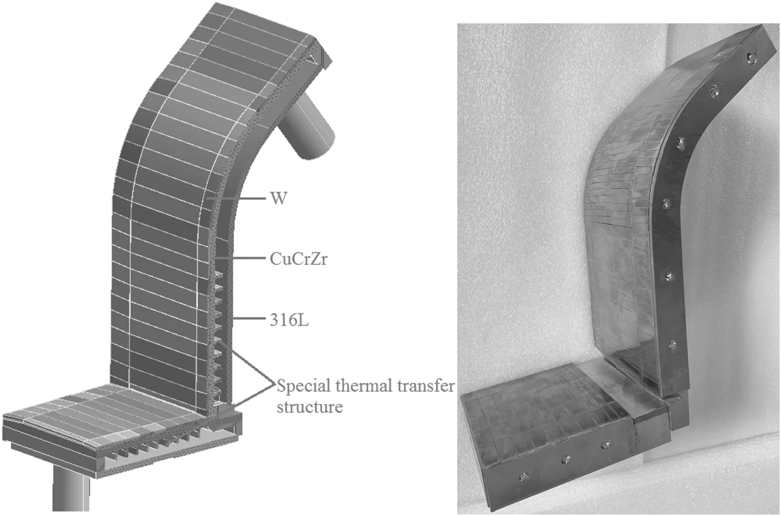
Figure 27.The model and prototype components of the flat-tile outer divertor target for EAST.
Acknowledgments
The study was supported by the National MCF Energy R&D Program (No.2018YFE0312300),the National Key Research and Development Program of China (No.2017YFA0402500),and the Science Foundation of the Institute of Plasma Physics,Chinese Academy of Sciences(No.Y45ETY2302).
ORCID iDs
 Plasma Science and Technology2021年9期
- Plasma Science and Technology的其它文章
- Recent results of fusion triple product on EAST tokamak
- Suppression and mitigation of inter-ELM high-frequency Alfvén-like mode by resonant magnetic perturbation in EAST
- Simulations of NBI fast ion loss in the presence of toroidal field ripple on EAST
- Reconstructions of velocity distributions from fast-ion D-alpha (FIDA) measurements on EAST
- Tomography of emissivity for Doppler coherence imaging spectroscopy diagnostic in HL-2A
- Comparison of natural grassy ELM behavior in favorable/unfavorable Bt in EAST
